Diodes used in mixers
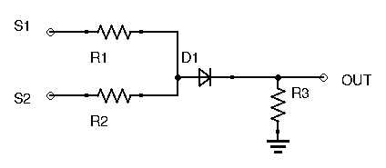
Suppose we have this circuit which is supposed to be an unbalanced frequency mixer. But how does the diode generate a signal with new frequencies at the output?
2 answers
You are accessing this answer with a direct link, so it's being shown above all other answers regardless of its score. You can return to the normal view.
Take a look at the circuit and try to see what function it will perform on the input signals to yield the output signal. For simplicity, let's consider the diode ideal, R1 and R2 the same, and R3 much larger.
R1 and R2 will average the two input signals onto the anode of the diode. The diode will clip this signal to the positive parts. In other words, it performs a MAX function with 0. The output is therefore Max(Ave(S1, S2), 0).
Now consider what this results is if you put in two sine waves. As an example, let's use 100 Hz for S1 and 101 Hz for S2. The average of the two is:

When the two input signals are in phase, they add, so the result is a full-amplitude sine. When they are out of phase, they cancel, so the result is 0. Since the difference in frequencies is 1 Hz, this adding and canceling repeats at a 1 Hz rate.
At this point, we still only have the two original input frequencies. Although the amplitude of the averaged signal is changing at 1 Hz, there is actually no 1 Hz component to the signal. It is simply the sum of two sines.
Now consider what happens when this signal is clipped to only the positive values:
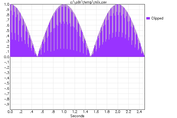
Now we do have a strong 1 Hz component. Hopefully you can see that if this low pass filtered to get rid of the 100 Hz and 101 Hz components, you'd be left with a 1 Hz signal.
Another way of looking at this circuit is that by adding two frequencies together, you get a result that varies in amplitude by the difference between those frequencies. D1 and R3 are essentially a quick and dirty AM demodulator. The result is a signal that is the amplitude envelope of the sum of the two input signals.
0 comment threads
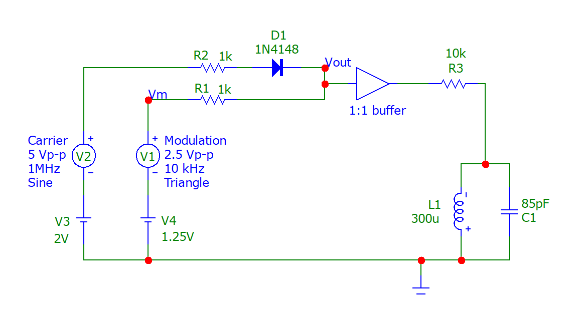
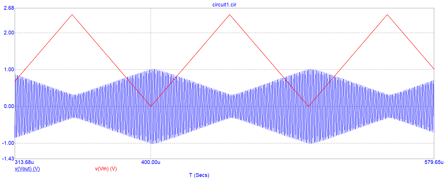
There are plenty of ways a single diode and a couple of resistors can perform multiplication (RF mixing). Consider this circuit that takes two inputs (a 1 MHz sinusoidal carrier wave and a 10 kHz triangle wave used to modulate the carrier): -
Now look at the signal on the cathode of the diode (Vout): -
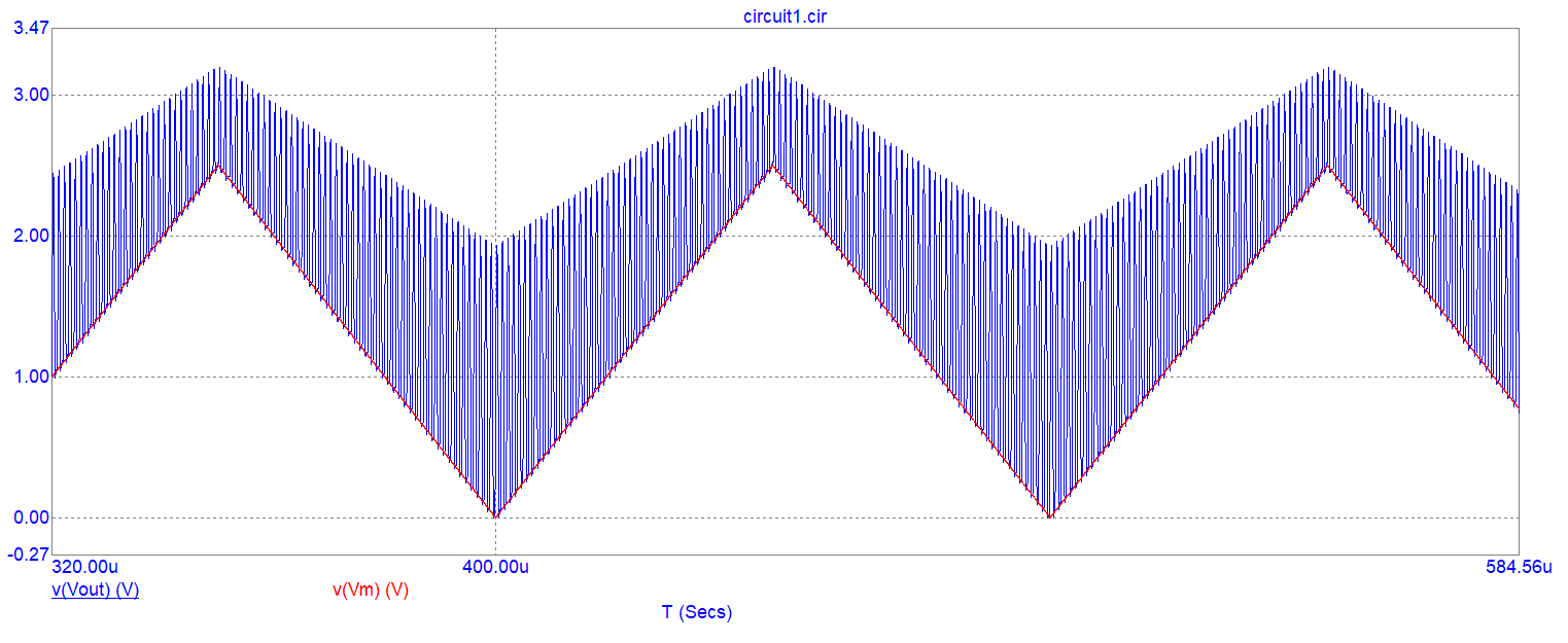
You can see that the 1 MHz signal (blue) is amplitude modulated by the triangle signal in red. This change is cyclic and repeating. It does now contain harmonics but, do you believe that (or would you rather see what the final waveform looks like after it has been band-pass filtered by L1 and C1). I guess you'd rather see it so, here is the output waveform at the node of R3 and L1/C1: -
So, do you believe that a diode can create new frequencies at the output?
Here's a closer view of the blue signal. It shows decent sinewave shape and it shows decent and linear amplitude modulation: -
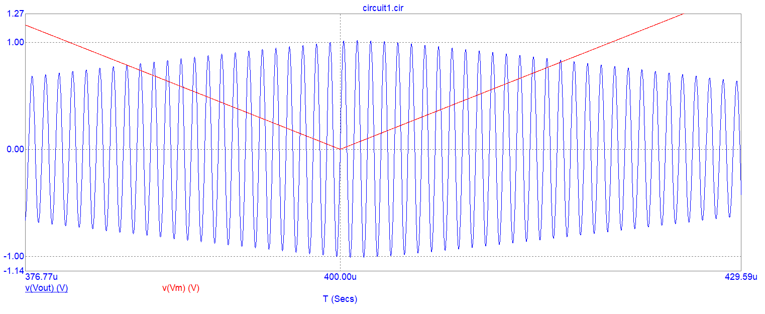
One diode, two resistors and a bit of DC biasing coupled with a buffer and a band-pass filter gives incredible amplitude modulation quality. But, it's all down to the diode and how the triangle wave cyclically causes it not to conduct the 1 MHz sinewave.
There are quite literally dozens of ways a diode can be used to do the same thing.
0 comment threads

1 comment thread