Adding resistance to varactor circuit
If we a varactor and we want to control let's say the resonant frequency of the circuit ,in my schematic we must add R1 correct?Else we create a low resistance path for current to flow not through the varactor so the "AC circuit" gets distorted from the "DC circuit".

So by changing the value of Rv we can change the capacitance of the varactor and the resonant frequency.
One last question if we deliver voltage to a house are there varactors which can handle 120V AC so we can create a panel of supply of voltage and we can regulate the quality of current in our loads from a switch?
2 answers
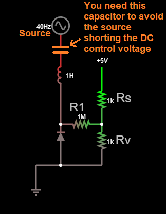
in my schematic we must add R1 correct?
No. Ultimately you are adjusting the varactor with a DC voltage that has a certain impedance. You can think of it as a Thevenin source.
In your case, the DC voltage is created by the divider of Rs and Rv, then the impedance increased by R1. However, you could just as well use higher values for Rs and Rv to get the same voltage at the same impedance.
In your example, Rs and Rv create a 2.5 V source with impedance Rs//Rv = 500 Ω. R1 then adds to that impedance to drive the varactor. The result at the left end of R1 is therefore 1 MΩ + 500 Ω = 1.0005 MΩ. You could have achieved the same thing by making Rs and Rv both 2.001 MΩ and replacing R1 with a short.
The topology you show is actually reasonable, especially when Rs and Rv are really a potentiometer. The output impedance of the pot will vary from 0 to 1/4 the pot value, depending on setting. Adding a deliberate resistance like R1 that is significantly higher than the pot value is a good way to provided a variable voltage with a reasonably fixed impedance.
The answer to your question is "no" because you asked if R1 must be used. While using R1 is a good idea, I showed how you get exactly the same effect at the varactor without using R1.
A few other issues:
- You should look up the capacitance ranges of available varactors. They are usually in the range if a few pF to 10s of pF. That's not useful to resonate with any reasonable inductor at 40 Hz. Varactors become useful at RF frequencies.
- You need a DC blocking cap in series with the AC signal you are trying to apply to the varactor. The DC level from the voltage divider sets the varactor operating center point, which effectively adjusts its capacitance. Without a DC blocking cap, the DC component of the signal you are applying to the varactor will mess up the operating point.
1 comment thread

1 comment thread