Find feedback of circuit
I have this circuit:
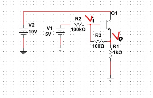
I think that R3 acts like a feedback path from the output to the input.However I am not sure what will happen if I change the value from 100Ohms to lets say 1kOhms.
I have this image in mind:
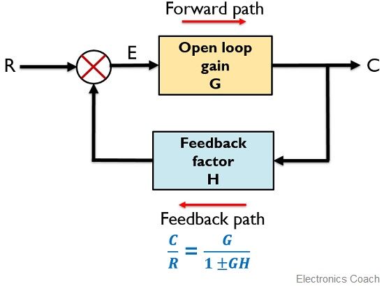
and I know the open loop gain must be close to 1 since we have a common collector(and relatively big value resistors) but I dont have any idea what kind of feedback this circuit has.
What kind of feedback is there in this circuit?And which is the value of the feedback factor?
2 answers
I must admit that your question (the described problem) is an interesting one. Speaking about the circuit (without consideration of the parts values), there are two feedback effects:
- At first, the resistor R1 provides negative feedback resulting in a low closed-loop gain slightly below unity.
- Secondly, the path R3-R2 conncts the emitter with the base (no phase shift) thereby providing a certain (rather small) amount of positive feedback.
- Thus, we have a "mixed" feedback (positive and negative) - provided that the parts values are correspondingly chosen.
- In addition, we also have feed-forward because the "output node" (emitter) is directly connected to the input (via R2-R3).
- Such a circuit is also known from opamp applications (positive and negative feedback simultaneously).
- However, the mathematical treatment of the circuit is not a simple matter because there is no real voltage output (zero output impedance) and no high-resisitve signal input (base node).
- Thereforte, the classical feedback block diagram (as shown in the first post) cannot be applied.
0 comment threads
You are asking about feedback in this circuit, and how R3 fits into that:
First, note that the circuit is an emitter follower, and has a voltage gain less than 1. Second, R3 bypasses the transistor for most input voltages.
The block diagram you show is usually meant to be used when the forward open-loop gain is relatively large, and some negative feedback is supplied. The math still works whether the above is true or not, but the result is rarely of any use when G is small. In this case G is a bit less than 1, not 105 like an opamp might have.
Another big gotcha is the DC offset from input to output. When the transistor is conducting, Vo will be one diode drop below Vi. Let's say the B-E voltage needs to be at least 600 mV to result in meaningful collector current. At 600 mV B-E, there will be 6 mA thru R3. That causes 6 V across R1.
For output voltages of 6 V or less (input voltages of 6.6 V or less), the transistor isn't really doing anything. The output is just the input thru the voltage divider of R3 and R1. There is no feedback anywhere.
Above about 6.6 V input, the transistor will contribute some of the output current. It will do so more as the input voltage goes higher, but that stops when the 10 V supply limit is reached. In this range, the circuit is a classic emitter follower with 100 Ω leakage around it for some reason. R3 is definitely not providing feedback. If anything, you could say it's providing some feed-forward.
You can think of an emitter follower as working on internal feedback in the transistor. There is surely much material on emitter followers out there.
1 comment thread

3 comment threads