Flyback transformer for Vout > Vin
This question is asked in an addition to https://electrical.codidact.com/posts/276436
Here is a Flyback converter mentioned there:
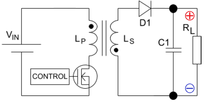
Design parameters are:
- Input voltage
125 volts - Output voltage
500 volts - Load resistance is
10 kohm - Transformer turns ratio
1:1 - Primary/secondary inductance
1 mH - Operating frequency
100 kHz
How is it possible to generate 500V on a transformer secondary given the 1:1 ratio?
2 answers
How is it possible to generate 500V on a trafo secondary given the 1:1 ratio?
In a DCM flyback transformer circuit, the secondary winding is being used as a pure inductor. So, once the primary is disconnected, the rate at which the core magnetic field collapses, dictates the secondary terminal voltage. If you want a bigger secondary voltage, you allow the core magnetic field to collapse at a higher rate.
Mathematically for an inductor, $V = L\dfrac{di}{dt}$
So, if the load is chosen to be a high value we know that $\dfrac{di}{dt}$ will be also high and, the output voltage will be higher than if the load was a low value.
So, providing that the secondary current ($i$) is of a high enough initial value to sustain $\dfrac{di}{dt}$ over the period in which the primary is disconnected, then we can generate whatever secondary voltage we want (within reason of course).
It's slightly different for CCM; in CCM the turns ratio does affect the output voltage as per this formula: -
$$\dfrac{V_{OUT}}{V_{IN}} = \dfrac{D}{N_{\text{P:S}}}\cdot\dfrac{1}{1-D}$$
This is because CCM is constrained to have a continual rising and falling primary-secondary current waveform with no hold or dwell period (unlike DCM): -
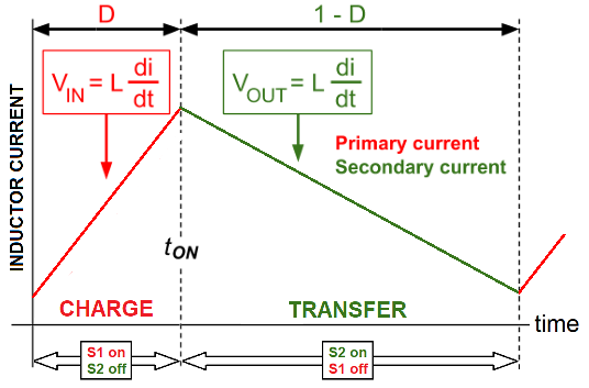
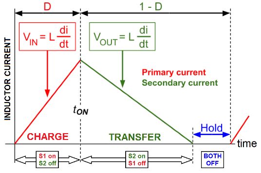
This means that the slopes of the rising and falling currents are totally dictated by the input voltage and the output voltage respectively. It cannot be in CCM if this were not the case. $$$$ But for DCM it's this: -
$$\dfrac{V_{OUT}}{V_{IN}} = D\cdot\sqrt{\dfrac{R_L}{2\cdot L_P\cdot F_{SW}}}$$
- $D$ is the duty cycle
- $N_{\text{P:S}}$ is the primary-to-secondary turns ratio
- $R_L$ is the output load resistance
- $L_P$ is the primary inductance
- $F_{SW}$ is the switching frequency
The devil is in the mathematical details of course. Images from my crappy website.
0 comment threads
A higher voltage can be produced at 1:1 ratio because the transformer is being run in flyback mode. Unlike normal forward mode, the primary and secondary don't conduct at the same time.
The input pulse builds up current in the primary. This does produce the same voltage on the secondary. However, the secondary is wired so that is a negative voltage, which is blocked by the series diode (D1) in the schematic you show. As a result no current flows in the secondary while voltage is being applied to the primary.
Since no secondary current flows, the primary looks electrically like just an inductor. The energy going into the primary goes into building up the magnetic field in the transformer core, just like in a simple inductor.
The primary current is then abruptly shut off. The circuit is designed so that the only place the energy in the core can go is out the secondary. The primary being shut off causes a secondary pulse of opposite polarity as when the primary was being charged. This time D1 allows conduction.
During the output pulse, the current in the primary is 0, so the transformer is again acting like an ordinary inductor. This time it's the secondary that is conducting. The output pulse is just an inductor discharge. The current decreases proportional to the reverse voltage applied to the secondary, which is the output voltage (plus the drop across D1).
The interesting thing about flyback mode is that the the output/input voltage ratio is independent of the transformer ratio. The transformer ratio does dictate the reverse voltage each side sees when the other is conducting. If you use a 1:1 transformer to step up a voltage by 5x, then the primary sees a reverse voltage of 5x during the discharge pulse, compared to the voltage applied to the primary during the charge pulse. You have to consider these voltage stresses carefully, and trade off the transformer ratio accordingly.
The transformer ratio also dictates the ratio of the two inductances. That, along with the voltage ratio determine the relative lengths of the charge and discharge times.
All these parameters need to be considered carefully and traded off against each other. One advantage of flyback mode is that you get a wide latitude of tradeoffs.
Of course there are disadvantages to flyback mode too. The magnetic core must be bigger for the same power transfer. In forward mode, ideally the energy is being removed from the magnetic field by the secondary as fast as the primary puts it there. In flyback mode, the entire energy of each pulse is stored in the core at one time.
0 comment threads

0 comment threads