Humming noise from a boost converter's inductor
My step-up converter makes audible noise both with and without a load.I am almost certain it is the inductor, because when I hold my finger on it I can feel vibration and it gets quieter. Unfortunately, I do not own an oscilloscope and cannot inspect what is going wrong. Here is the schematic:
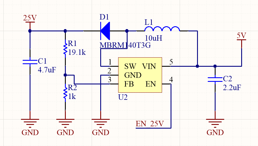
All the capacitors are ceramic, inductor is FXL0530-100-M, and the converter datasheet can be found here . On page 14, FIGURE 6-8 the recommended values are shown. Only thing I have changed are resistor values to match my output voltage, but this is a minor change. I read about audible issues with converters, and one of the points mentioned was that picking an IC with a higher switching frequency can help, but this particular one is at 1MHz, well above the one mentioned in the article I read.
What could be the reasons for this humming noise, and how could they be mitigated?
2 answers
A couple of problems stick out; one glaring and one a little subtler. Read this in the data sheet: -
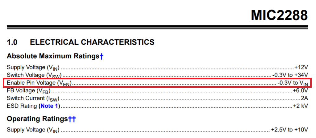
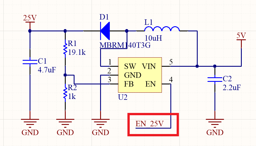
You have the enable pin connected to your 25 volt output. I'm not saying this is definitely causing your problems but you might well have broken the chip in some way that gives you the symptoms you are seeing: -
Other than that your circuit values looks compatible with the data sheet but what is the output load you are using?
The inductor you have used isn't the Murata LQH43CN100K03 part recommended in the data sheet of the chip - is there a reason why you have chosen that part? I'm not convinced that the inductor you have chosen is suitable for such high frequency operation. In the data sheet they don't give much detail about self-resonant-frequency whereas the Murata part is quoted at 23 MHz.
The inductor you have chosen only says that the inductance was tested at 100 kHz and this, in my opinion, hints that it probably isn't suitable for a boost converter running at nominally 1.2 MHz.
First, draw schematics properly when you ask others to look at them. Your right to left flow is rather annoying.
There are two main possibilities for this circuit to cause noise, the inductor and the output capacitor.
Inductor
The inductor can make sound for two reasons:
- Every bit of wire is subjected to a sideways force due to the magnetic field. As that changes, the force on the wire changes. The windings aren't meant to move, but small vibrations happen anyway.
- The magnetorestrictive effect. Some magnetic materials change size slightly as a function of the magnetic field.
Capacitor
The capacitor can make sound due to the piezoelectric effect. This is the electrical analog of the magnetorestrictive effect. The material changes size slightly as a function of the electric field.
The reverse is also true, meaning the voltage on a ceramic capacitor can change slightly due to applied force. This undesirable property even has a name, called microphonics. This is why ceramic capacitors are usually banned from the signal path of sensitive audio circuits.
4.7 µF for the output cap seems rather small. I didn't read the whole datasheet, but the examples I saw used 10 µF. Maybe it's within specs, but there is certainly no harm in making it higher. That would make the output voltage smoother, which includes less voltage change across the capacitor.
Instability
The above explains why this circuit could make sound at the switching frequency. Since that's 1.2 MHz according to the datasheet, that's clearly not what you're hearing. This is actually a symptom of a worse problem, which is that the controller is not stable.
What is happening is that the controller is going meta-stable. Over a number of pulses, the voltage goes up. This causes the PWM to get cranked back for a number of pulses. The result is oscillation at a lower frequency than the switching frequency. This is what you are hearing. You really should fix that.
I'd try paralleling another capacitor across C1. You don't give any specs on C1, so we don't know the voltage rating. For some ceramic caps, the capacitance drops off significantly with voltage. If this is a 30 V cap, for example, then the capacitance may be significantly less than 4.7 µF at 25 V.
I see now that there is a table on page 12 of the datasheet, which says 4.7 µF is sufficient above 16 V output. That doesn't mean that higher values are bad.
Even though the datasheet only says the chip needs 1 µF input capacitance, there is clearly no reason you can't use more. Surely this part works with a 0 impedance voltage source as input. I'd put 10 µF there since that's cheap and easy.
Voltage step-up ratio
You are asking for a voltage step-up ratio of (25 V)/(5 V) = 5. That requires a nominal PWM duty cycle of 80%. That's close to the maximum duty cycle of 85% this chip is intended for.
Diode
At these voltages and currents, you really should be using a Schottky diode. They have half the forward drop, and are very fast. I didn't look up your diode, but another possible problem is that it has too long of a reverse recovery time. At over 1 MHz switching speed, this is very important. Any ordinary diode is far from good enough here.
Fixes
You may still be in spec, but right at the edge pushing some of the limits. Use a little intuition and try to make it as easy for the chip as possible. Like with most things in life, trying to slide by with the bare minimum gets you in trouble eventually when everything else isn't just right.
Using a bigger input cap is a no-brainer.
Using a Schottky diode is a no-brainer, and in fact the lack thereof may well be causing significant trouble.
Most likely a larger output cap would help. The meta-oscillations are due to control instability. The most likely cause of that is insufficient output capacitance. Your "4.7 µF" cap probably isn't 4.7 µF at 25 V.

1 comment thread