MAX809's Irregularity Depending on Load
I have a MAX809 with RESET pin connected to the gate of IRLML6344. I will rephrase my question.
At 5 V, RESET is also 5 V and the LED lights up. But if I add the fan, RESET drops to 0 V and draws 140 mA. Adding a 100 nF cap solved this problem. What is happening here?
Then I added a MOSFET to the circuit but depending on what is connected to LOAD2, RESET triggers at different values. I tried with 0.1 µF, 1 µF, and 10 µF. But RST triggers outside the specs. (specs is RESET off at 2.80 V and RESET is on at 2.93 V)
Using 100 µF at C2,
RESET is low at 2.80 V and high at 2.93 V when load is only an LED.
RESET is low at 2.86 V and high at 2.93 V when load are LED and a DC fan with 150 mA current draw.
RESET is low at 2.9 V and high at 3.2 V when I added a buck converter (LM2596) with nothing connected to it.
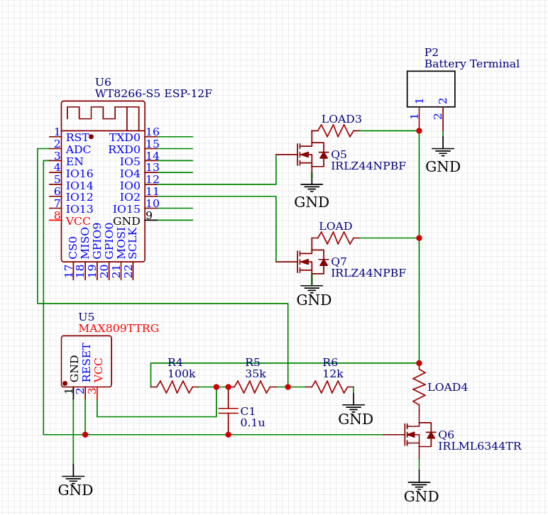
For context, this is what I planned to do.
1 answer
Before we get into your problem, there are a few things to say about your descriptions. You need to step back and think about what we know and don't know, then learn to communicate specifications properly. That includes always making it clear what a number refers to, and using consistent names.
We do engineering here, so favor engineering notation. There should be 1 to 3 digits left of the decimal point, then the appropriate factor of 1000 multiplier symbol added in front of the units. For example, we don't say 0.02 volts, but rather 20 millivolts, abbreviated 20 mV. Don't forget the space between the number and its units.
It is still very early for this Q&A site, so we are currently a little more forgiving to get things going. In the long run, once the question volume is higher, we will be less tolerant of sloppily written questions. One reason I'm pointing out the problems with your question is that I want it to be clear in the future that something similar is not acceptable.
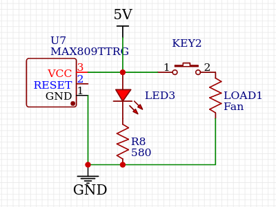
For reference, here is your circuit:
At 4V
When what is a 4 V?
RST is also 4V
What is "RST"? There is no such node shown in the schematic.
I'll take this to mean that RESET# is high when the supply (labeled "5V") is at 4 V. That means the reset chip considers the supply voltage high enough and is not asserting the reset state. So far so good.
Now you apparently close pushbutton KEY2, and RESET# goes low again. That is reasonably expected. Whatever load is connected when KEY2 is closed causes enough momentary current draw so that the reset chip's VCC input drops below the threshold, and it re-asserts the reset output. I didn't look at the datasheet, but it probably holds it there for some minimum time regardless of what VCC then does.
Basically, the reset chip is doing its job.
Adding a 0.1uF cap solved this problem.
Again, the grown-up way to say that is 100 nF, not 0.1 µF. Also note the space between "100" and "nF". By the way, when you do need to use the symbol for "micro", it should be the lower case Greek letter when available. Using "u" is acceptable for something like plain text, but we use HTML here. The proper symbol is always available using "µ", as I did above.
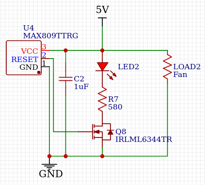
Anyway, it seems you are referring to the additional capacitor in this circuit:
A cap solving this problem makes perfect sense. The initial pulse of current drawn by the load when first switched on now comes from the cap instead of all the way back from the power supply. That avoids the impedance of the lines back to the supply, and that of the supply itself. As a result, there is a much smaller temporary dip in voltage on the VCC input of the supervisor chip.
100 nF seems rather skimpy. It might be right on the edge for all you know. I'd put a 1 µF cap to ground on pin 1 of KEY1.
So I added the MOSFET to the circuit but RST drops to 0V again when I connect a load.
When Q4 is on, you have a LED directly connected between the 5 V supply and ground. One or the other is going to give. In your case it is apparently the 5 V supply, at least for a while.
Let's say this is a typical "green" LED with 2.1 V forward drop, and is rated for 20 mA maximum. Let's say that 5 mA is enough to light it usefully in your situation.
You need a resistor in series with the LED to drop the remaining voltage, at the desired current. With 5 V applied to the resistor and LED, the LED takes 2.1 V. That leaves (5.0 V) - (2.1 V) = 2.9 V across the resistor. By Ohm's law, the resistor value is:
(2.9 V)/(5 mA) = 580 Ω
So put about a 580 Ω resistor in series with the LED. As I said earlier, instead of C1 as shown now, put 1 µF between pin 1 of KEY1 and ground.
A reset chip is the one exception where you don't want a bypass cap. The job of a reset chip is to hold the rest of the circuit in reset unless the supply is up and stable. You therefore need it to see glitches on the supply. Putting a bypass cap across the reset chip prevents it from seeing glitches that might cause the other chips to behave erratically. When there are glitches on the supply, you want those other chips to be held in reset (else why use a reset chip in the first place?).
You haven't explained what you are trying to accomplish, but the above makes no sense. When Q2 is turned on, it will short the battery.

1 comment thread