Activity for MissMulan
| Type | On... | Excerpt | Status | Date |
|---|---|---|---|---|
| Question | — |
BJT common emitter amplifier equivalent circuit (π hybrid model) Im studying the equivalent model of a BJT common emitter amplifier at high frequencies.At university we tought that the BJT at high frequencies looks something like this: 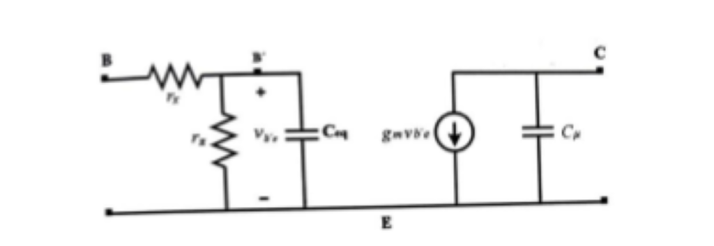 However when designing a common emitter amplifier we h... (more) |
— | over 1 year ago |
| Question | — |
Thermal stability coefficient The thermal stability coefficient is defined to be: $S = \frac{dI{C}}{dI{CBO}}$ where $I{CBO}$ is the reverse current of the BJT when voltage isnt applied to the base of the BJT. In case of a BJT biased with 2 sources $I{C} = \beta \cdot I{b}+(\beta +1)I{CBO}$ However my textbook says that $... (more) |
— | over 1 year ago |
| Question | — |
Circuit which create ac sine wave from dc pulsed signal A full wave rectifier converts a sine wave to DC pulsed signal of double frequency. Is there a circuit which does the reverse process? (more) |
— | over 1 year ago |
| Question | — |
Need help design a digital circuit which divides two binary numbers Before the circuit here are the digital blocks which have been already designed and exist as part of the division block 1 bit subtractor: 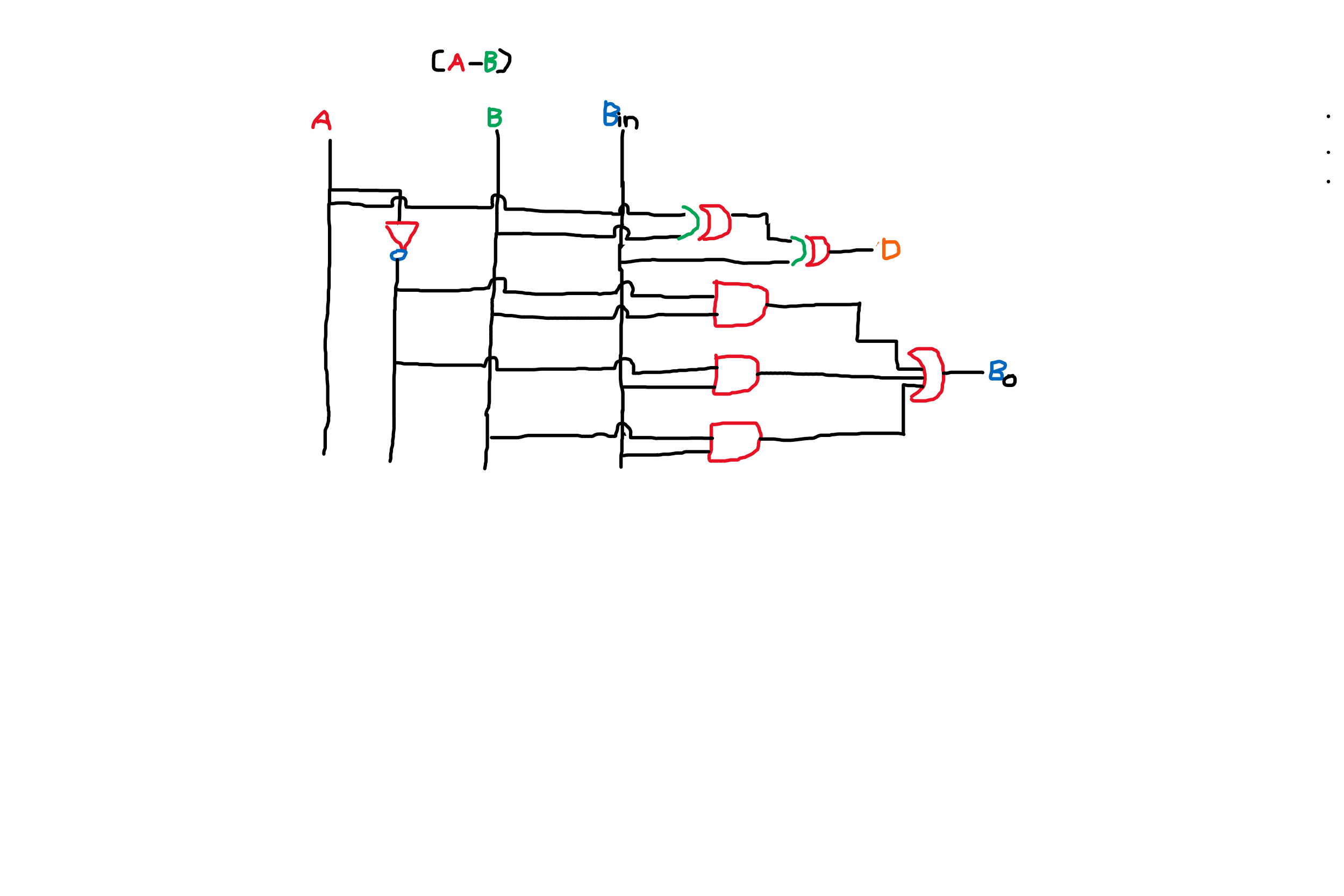 2 bit subtractor(in the digital block diagram of the division block there is a 3 bit... (more) |
— | over 1 year ago |
| Question | — |
Op Amp Hartley oscillator Im designing a Hartley oscillator this time with a opamp providing the open-loop gain.I have tried drawing the small-signal analysis of my circuit to use KVL and KCL to find the conditions of operation of my Hartley oscillator but now I am stuck.  |
— | almost 2 years ago |
| Question | — |
Results of analysis of Hartley oscillator dont make sense I want to find the conditions of oscillation of the following Hartley oscillator.I have attached a load (ZL) to my Hartley oscillator Image alt text I have written KCL for nodes A,B: For node A: $$\frac{V{A}}{sL{1}} + \frac{V{A}}{Z{L}}+\frac{V{A}}{R{C}}-sC{1}(V{A}-V{B})+g{m}V{x} = 0 \righ... (more) |
— | almost 2 years ago |
| Question | — |
Modelling tunnel diode relaxation oscillator I have been trying to model this oscillator 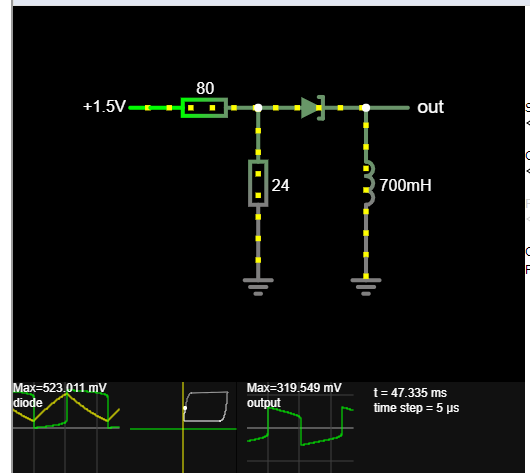 I was wondering if we can somehow predict the frequency of the oscillations.For small currents inside a diode from the Shockley diode equation $$ e^{x}-1 = x$$ -> $$I{D} = \frac{x}{... (more) |
— | almost 2 years ago |
| Question | — |
DC-DC converter using Hartley oscillator and transformer Instead of using a buck or a boost converter can we use for DC-DC conversion the circuit Im going to describe in the next lines? First we begin with a Hartley oscillator whose output is fed into a transformer with N:1 turns ratio between primary and secondary windings. Then we rectify the voltage ... (more) |
— | almost 2 years ago |
| Question | — |
Small signal analysis of BJT in saturation region The small signal analysis of a BJT when the BJT is in amplification mode: 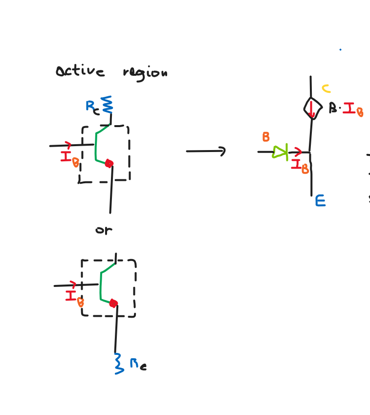 is easy.However what happens when the BJT is in saturation mode?  Can we rep... (more) |
— | almost 2 years ago |
| Question | — |
Design high -pass filter with 2 points of the bode plot Im designing a high-pass filter which has a gain of -8dB at half of the roll-off frequency and I am stuck ,I dont know how to continue the design. In the bode plot of that filter we have 2 points:1 is at (fc,-3dB) and the other is at (fc/2,-8dB).What information must I extract to find the transfer... (more) |
— | almost 2 years ago |
| Answer | — |
A: Band pass filter given cutoff frequency and bandwidth My mistake was taking the third relationship $$ \frac{1}{RC} $$ which says how to find the bandwidth of a parallel RLC filter but we have a series RLC filter. Now solving the system : $$ LC = 100020001 , \frac{R}{L} = 2 $$ gives us the correct ratio between C1 and R1 and L1 with more detail: ... (more) |
— | almost 2 years ago |
| Question | — |
Band pass filter given cutoff frequency and bandwidth I have decided to try design a band-pass filter with a cut-off frequency of 10kHz and bandwidth of 2 Hz. Image alt text $$ \frac{1}{\sqrt{LC}} = 10001 \rightarrow LC = 1/100020001 sec^{2}$$ $$ \frac{R}{L} = 2Hz$$ $$ \frac{1}{RC} = 2Hz$$ Here is what I have done but if I plug the value... (more) |
— | almost 2 years ago |
| Question | — |
Finding voltage gain of Hartley oscillator I am trying to find the AC analysis of a BJT Hartley oscillator but I cannot continue. How do I find the voltage gain? When no feedback is there, we just find the output resistance and the current inside the output resistance and find the input resistance and the current inside the input resistance ... (more) |
— | almost 2 years ago |
| Question | — |
Complex frequency of a pole If we have the transfer function of a LC high pass filter: $H(s) = \frac{sL}{sL+\frac{1}{sC}}$ If we want to find the pole of that filter in the end we get: $s = \frac{j}{\sqrt{LC}}$ and for a sinuisodal input signal $s = j\omega$ the pole exists at the resonant frequency $\omega{r}$ ... (more) |
— | almost 2 years ago |
| Question | — |
Effect of adding stages to a filter Suppose we have a RC low pass filter of 1st order. If we add multiple stages every time we add a RC stage identical to our original does the slope of the curve in the bode plot db/Hz becomes wilder but the cutoff frequency remain the same?And is there a formula if we know the slope of the curve a... (more) |
— | almost 2 years ago |
| Question | — |
Cutoff frequency of single phase transmission line Signals with frequency above the cutoff frequency of a transmission line cannot be transmitted through the transmission line. But how can I calculate the cutoff frequency of a single phase transmission line? I had been reading this/02%3ATransmissionLines/2.02%3ATransmissionLineTheory) page befo... (more) |
— | almost 2 years ago |
| Question | — |
How to design a low-pass filter when certain conditions must be met I am designing a low-pass filter with cut-off frequency = 100Hz and after the cutoff frequency from -3dB to -10dB the average decrease in db/Hz = -0.1 db/Hz.I know how to design a low-pass filter with cut-off frequency of 100Hz however I cannot meet the 2nd condition of the filter.How do I achieve s... (more) |
— | almost 2 years ago |
| Question | — |
Find Q point in common base BJT configuration Suppose we have this graph: 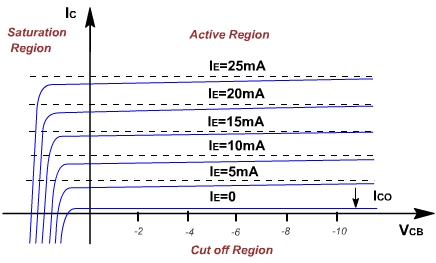 How can we find the operating point (Q)?In common emitter collector we just draw a line from the vertical axis (Ic) at the point (0,VCC/RC) to the horizontal axis at the point(VCC,0) and where ... (more) |
— | almost 2 years ago |
| Question | — |
Re model of transistor is the same in 2 different configuration I was studying the Re model of a transistor: 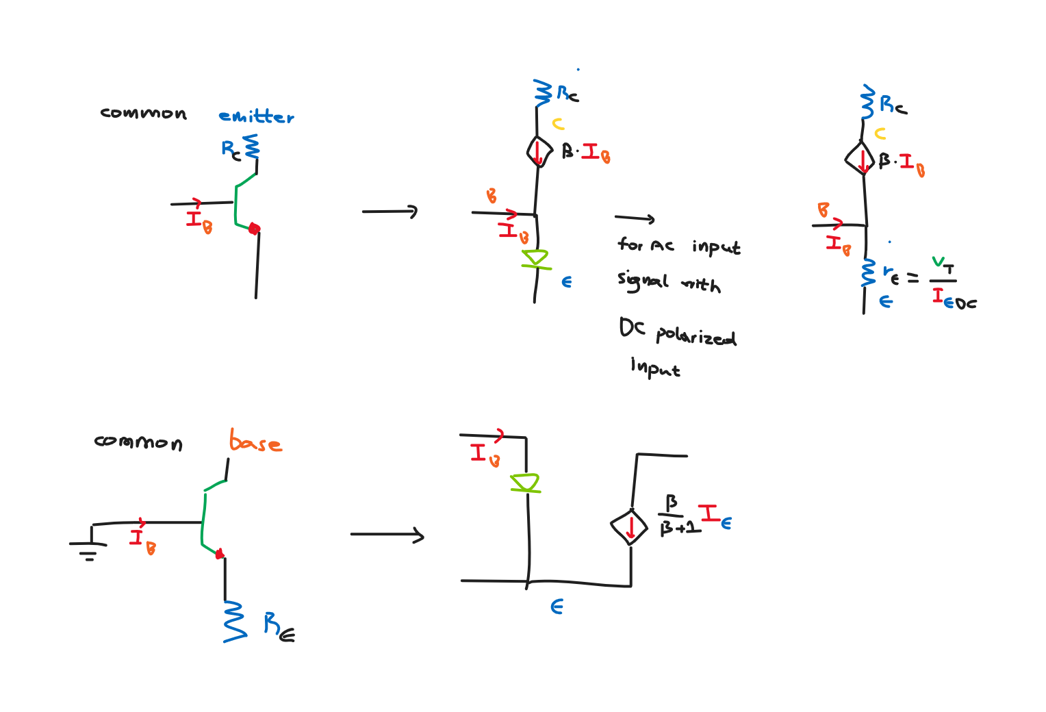 But the Re model for 2 different configurations (common emitter and common base )turns out to be the same! I don't know why I am really confused.How is this possible? (more) |
— | almost 2 years ago |
| Question | — |
Identification of semiconducting electrical components We identify semiconducting electrical components this way: The first digit represents the number of pn junctions inside the semiconducting device The two or more digit number starting at position 3 represents the searilized identification number In the second digit I have seen only diodes wi... (more) |
— | about 2 years ago |
| Question | — |
Choosing Y value in photoresistor graph I have designed a graph of the current in a photoresistor related to the brightness of light which hits the photoresistor. 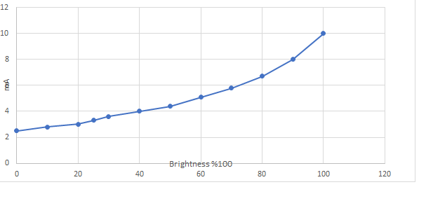 Our professor told us that it is more correct to draw the Current/Brightness graph than the Resistan... (more) |
— | about 2 years ago |
| Question | — |
Phase shift between phase and line quantities In a 3 phase Star source-Star load circuit the phase voltage has different phase than line voltage and in a 3 phase Delta source-Delta load circuit the phase current has different phase than the line current.Why? (more) |
— | over 2 years ago |
| Question | — |
Bandwidth of serial signal Suppose we have this stream of data.Let's assume the data stream lasts 1 sec.  How do we find the bandwidth of the data?Do we Fourier transform the signal in order to find its components in the frequency domain? Assume ... (more) |
— | over 2 years ago |
| Answer | — |
A: How can we grow this community? 1. When you search on Google about a specific electronics/electrical engineering question, EE Codidact is not in the first few results so I think users should try to upload relevant content frequently and self-answer the question. 2. On Chemistry Stack Exchange, you can ask a question and eve... (more) |
— | over 2 years ago |
| Answer | — |
A: How to treat data communication questions? I may be a little bit biased on this one because it was my question which started this thread but : I don't think data communication question should be generally off-topic because it evolves binary logic and the way the data are sent/received is through electric signals. (more) |
— | over 2 years ago |
| Question | — |
Splitting of message inside the layers Assume a app generates a message (stack on computer).Each layer of the sending entity will put then control information in the data depending on the protocol and transmit the data to the next lower layer .  Each layer of the ... (more) |
— | over 2 years ago |
| Question | — |
Asynchronous connection question Assume we have a channel and send 7-bit data(0100100) asynchronously with 1 parity bit(0).Suppose the start bit is 1.The end bits are in the same logic level with the idle state of the channel(0).How does the receiver understand the end bits?In my case the last 2 0s could have been the end bits but i... (more) |
— | over 2 years ago |
| Question | — |
What is minimum resolution here? In this datasheet it says that the minimum resolution is 0.1uA for the 10mA range.What is this minimum resolution?Is it the sensitivity of the multimeter for the 10mA range? (more) |
— | over 2 years ago |
| Question | — |
Resistance of digital ampmeter Can we find the internal resistance of a multimeter ,when we use the multimeter like a ampmeter, from its datasheet? I am trying to find the internal resistance of IDM 505 and I went to the datasheet to the current section and the most relevant thing I could find was the accuracy but as far as I k... (more) |
— | over 2 years ago |
| Question | — |
Capacitors of voltage regulators Assuming we have a voltage regulator : 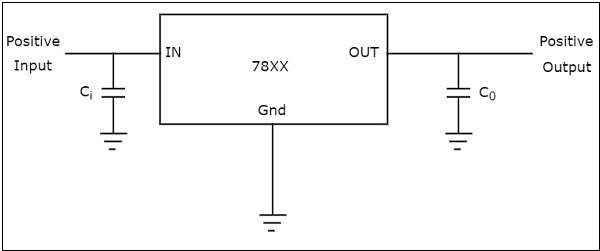 Why do we have to ground Vin and Vout using 2 capacitors just like that?Co could be to provide a low resistance path to GND at high frequencies but what is the role of Ci? (more) |
— | over 2 years ago |
| Question | — |
Confusion with Wikipedia article on multivibrator circuit A while ago I made a question about the monostable multivibrator .Lets get a picture of it: 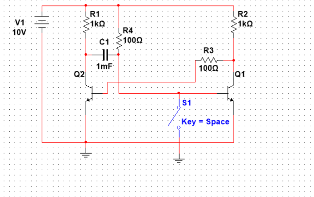 When switch is closed it enters its unstable state and it eventually returns to the stable state However Wikipedia states that thi... (more) |
— | over 2 years ago |
| Question | — |
Find feedback of circuit I have this circuit: 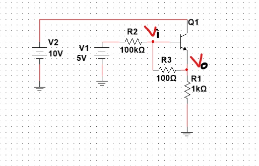 I think that R3 acts like a feedback path from the output to the input.However I am not sure what will happen if I change the value from 100Ohms to lets say 1kOhms. I have this image in mind:  |
— | over 2 years ago |
| Question | — |
Capacitance gain using conductive core for inductors I have learnt that if we have 2 parallel conductive plates and we seperate them the capacitance is increased if we put a good conductor between the plates. Now the resonant frequency of a inductor(1mH) is about 100kHz which doesnt make it practical for application when the desired output frequency... (more) |
— | over 2 years ago |
| Question | — |
Change of pins in monostable multivibrator In monostable multivibrators we use a trigger signal applied to the base of the transistor which is usually off to enter the astable region 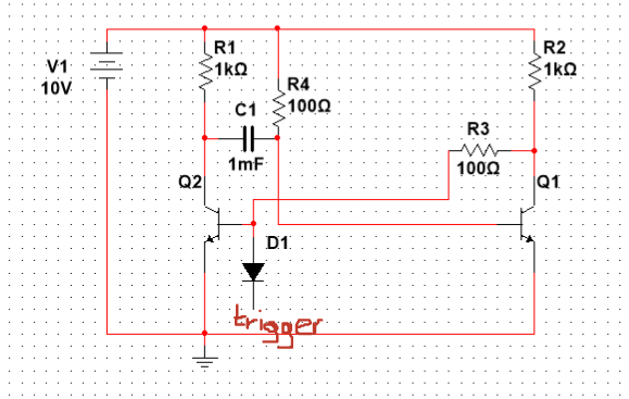 Can we instead have a pin which is connected directly to the base of Q1 and when that... (more) |
— | over 2 years ago |
| Question | — |
Electrolytic vs ceramic capacitors about self-resonance frequency Which capacitors have smaller self resonance frequency?I would bet my money on electrolytic capacitors because they are usually much bigger than the ceramic capacitors however I don't know if they self inductance changes as well so here we are asking this (more) |
— | over 2 years ago |
| Question | — |
Capacitance of inductor What is a typical value for capacitance of a real inductor? Does this internal capacitance exist only under AC and not DC? (more) |
— | over 2 years ago |
| Answer | — |
A: Parallel RLC circuit It all depends on the values of the components:If  the system will very slowly decay until the energy of the system reaches 0. If  the system underg... (more) |
— | over 2 years ago |
| Question | — |
Parallel RLC circuit How to find the equation of voltage of the top common node of R1,L1 and C1 after the switch is moved? 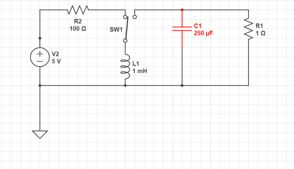 (more) |
— | over 2 years ago |
| Question | — |
Inductance vs frequency Suppose we have a sine signal applied to a inductive load. Is the inductance of the load changed if the frequency of the signal is changed? (more) |
— | over 2 years ago |
| Answer | — |
A: Series RLC circuit It all depends on the values of the components:If  the system will very slowly decay until the energy of the system reaches 0. If  the system und... (more) |
— | over 2 years ago |
| Question | — |
Series RLC circuit How to find the equation of current of the RLC circuit after the switch is moved? 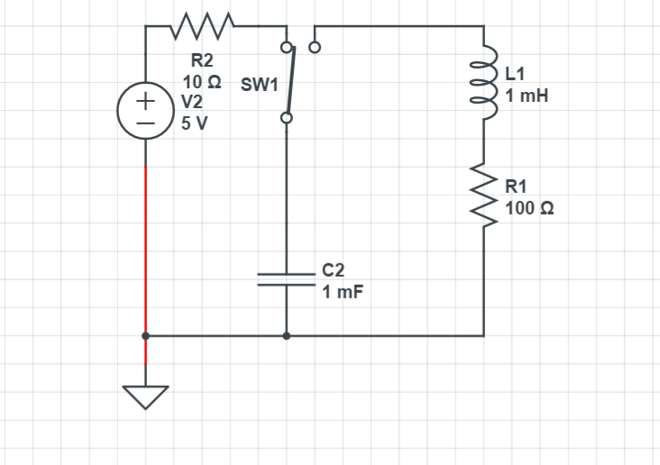 (more) |
— | over 2 years ago |
| Answer | — |
A: Coupling of inductors When 2 inductors share the same magnetic field they become coupled and besides their self inductance they have a mutual inductance as well. For this circuit: 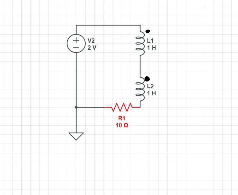 Now current entering one coil marked with a dot, produces a ... (more) |
— | over 2 years ago |
| Question | — |
Coupling of inductors Which will be the total series inductance?  (more) |
— | over 2 years ago |
| Answer | — |
A: Voltage and Current of capacitor After the switch is closed: hi The general formula for finding the voltage of the capacitor is: hi where Vf is the voltage of the inductor after infinite time,Vo is the voltage of the capacitor at the time the switch is closed Because capacitors resist any change in voltage hi ... (more) |
— | over 2 years ago |
| Question | — |
Voltage and Current of capacitor How do I find the voltage of the capacitor and the current through the capacitor after the switch is closed? (more) |
— | over 2 years ago |
| Answer | — |
A: Current and voltage of inductor After the switch is closed : hi The general formula for finding the current through the inductor is this: hi where If is the current through the inductor after infinite time,Io is the current of the inductor at the time the switch is closed. Because inductors resist any change in curre... (more) |
— | over 2 years ago |
| Question | — |
Current and voltage of inductor How do I find the current through the inductor and the voltage of the inductor after the switch is closed? (more) |
— | over 2 years ago |
| Answer | — |
A: Select resistor for a diode A diode obeys the Shockley diode equation and for this circuit we have:hi hi The current through the diode must not pass a limit so for LTL-307EE we go to the datasheet to find the maximum current before the diode is destroyed: For the LTL-307EE at 20C we have 10^4 A Isat and Vth=0.026V... (more) |
— | over 2 years ago |
| Question | — |
Select resistor for a diode Suppose we have this circuit see me How do I pick a appropriate value for the resistor R1? (more) |
— | over 2 years ago |
| Question | — |
Diode like a frequency mixer Based on this paper on Wiki a diode can be described as a frequency mixer due to the exponential relationship between current and voltage.What I don't get from which point to which point do we measure the voltage with the different frequency(or whatever)? So if we connect a oscilloscope to the cir... (more) |
— | over 2 years ago |