Trouble understanding how to use adjustable LDO regulator
The question being asked
Ultimately, I want to know why the output voltage wasn't the expected (via calculation) 11.72V when the estimated drop-out voltage at the ~0.1A load was about 200mV. The input voltage to the regulator was 12V.
Hi everyone, first off, I wanted to say I am a big fan of some of you: Olin Lathorp, Tony Stewart, Andy AKA. I can't mention how many questions on StackExchange I've looked at where at least one of you provided your expertise and helped me as well as the posters.
I'm having trouble with understanding how to use a LDO linear voltage regulator I bought on Digikey. It's the MIC29303WT adjustable regulator found here: https://www.digikey.com/short/pbnpj419.
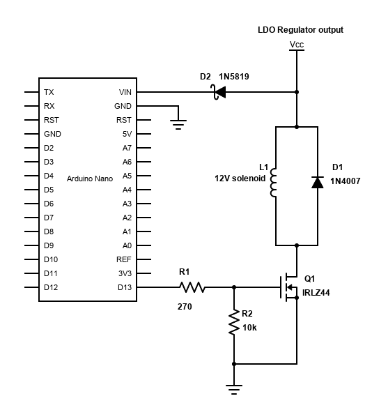
I want to use it to further regulate a +12V input voltage for use with an Arduino and a relatively low current draw solenoid (12V 0.1A solenoid from American Science & Surplus). There's an Arduino Nano connected to the output of the regulator. The Nano has an output that connects to the gate of an N-channel IRLZ44 MOSFET that controls the current path for the solenoid. One lead of the solenoid is connected to the aforementioned regulator output and the other is connected to the MOSFET drain. There's a flyback diode across the solenoid to protect against inductive spikes, just in case.
For setting up the regulator, I looked at the MIC29303WT datasheet and identified the drop-out voltage for the MIC29303WT as 80mV to 175mV MAX for an output current of 100mA. Moving to the next listed output current, 1.5A, we see 220mV of drop-out. For me, I interpreted this as ~200mV dropout should be expected for my solenoid + Arduino load. So my output voltage had to be at most 11.8V with a 12V input to expect steady operation at the expected current draw... at least that's my understanding.
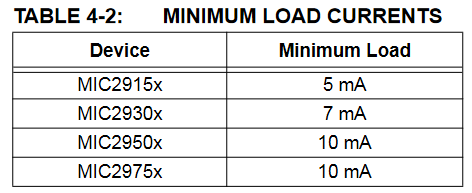
I looked at the minimum load "bleed" current required for proper operation in the table and figured it was 7mA, helping me set R2:
7mA = 11.8V/R2 -> R2 <= 1.7kOhm I chose R2 to be 1.5kOhm.
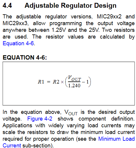
Looking at the adjustable regulator formula let me figure out R1:
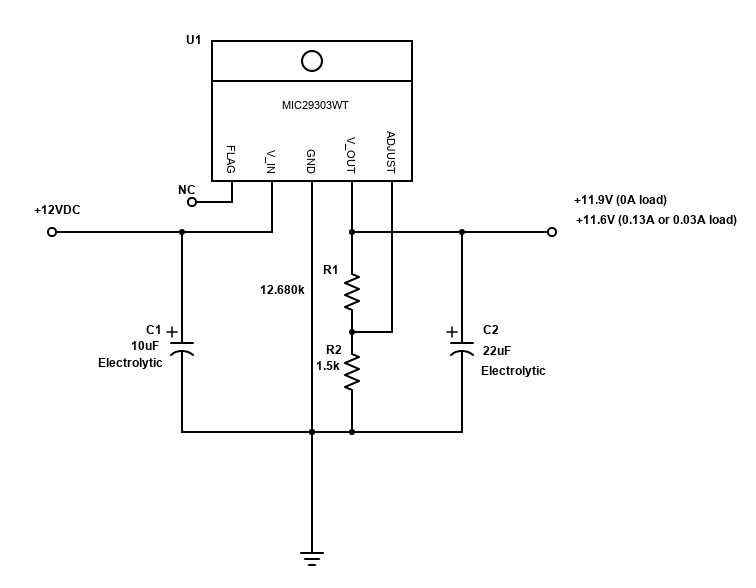
R1 = 1.5kOhm[(11.8V/1.24)-1] -> R1 = 12.774kOhm I chose R1 to be a 12kOhm resistor in series with a 680 Ohm resistor.
With R1=1.6kOhm and R2=12.68kOhm, the expected regulator Vout is 11.72V. This is under the expected drop-out voltage amount of 0.2V away from the 12V input... right? 11.8V should be that limit. Therefore, the output voltage should remain regulated at about 11.72V regardless of whether the additional 0.13A load (on top of the 7mA bleed current) is present or not.
The "problem" I am running into is that the voltage output of the regulator is not what I expected. When I hook the circuit up to my bench-top power supply, the regulator output voltage is 11.6V (oscilloscope says 11.6V, power supply says 11.5V) when the Arduino is connected. The Arduino draws 0.03A, according to the power supply. When the 0.1A solenoid is activated, the regulator output voltage remains at 11.6V, but the current draw is 0.13A, as expected. When I disconnect the Arduino and solenoid from the breadboarded circuit, the current draw is 0.00A and the regulator output jumps up to 11.9V (oscilloscope says 11.9V, power supply says 11.8V).
One thing that I suspect could be at play is Microchip's definition of what drop-out voltage is, and their operating conditions for the stated drop-out voltage at 0.1A, 1.5A, etc. I could be running the regulator out of spec, since there isn't at least a 1V difference between input and output voltage.
But wouldn't that defeat the purpose of a low (sub-1V) drop-out regulator? I expect I just don't understand how to use it or have misunderstood some part of the datasheet. Any clarification on why the output voltage isn't the calculated/expected 11.72V would help a lot. Let me know if you'd like any more information and I'll try to provide it. Thank you!
Update
With Lundin's advice, I decided to replace the R1 and R2 resistors for the adjustable regulator. In doing so, I realized I calculated the resistors for minimum bleed current for proper operation wrong. I had divided the output voltage by R2 only, instead of serial R1 + R2, a considerably higher resistance. Dividing by R1 + R2 meant a bleed current of about 0.83mA.
11.72V/(12680+1500 Ohms) = 0.0008265... A
This is of course a lot less than the 7mA the datasheet says is needed for the MIC29303WT to work properly.
Lundin suggested to use lower resistor values and try to use the standard ones directly instead of combining them, so I did that.
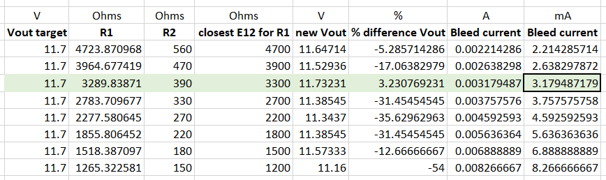
I chose R1 to be 3.3kOhms and R2 to be 390 Ohms. The new bleed current is expected to be about 3mA, which is still lower than 7mA. However, with the Arduino connected (as it will be in the application setting), the current draw will always be at least ~30mA on top of these 3mA from R1 + R2. At the very least, though, this process explained why the output voltage previously rose above 11.7V when the Arduino + solenoid circuit were disconnected from the output.

With the new resistors in place, Arduino connected, and nothing else changed, I see that the output voltage on the oscilloscope is +11.7V DC when I zoom-in on the voltage scale. My particular Gwinstek GDS-1052-U oscilloscope won't tell me beyond the tenths place if it really is 11.72V but that isn't a big issue at all. The output remains at 11.7V regardless of whether the solenoid is activated or not. I think everything's working properly.
Hopefully this helps someone in the future. Thank you Lundin and Olin for your help!
2 answers
You are accessing this answer with a direct link, so it's being shown above all other answers regardless of its score. You can return to the normal view.
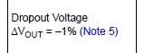
Your question is quite long, so it's not clear what exactly you are asking. It seems the main point is what Microchip means by Note 5 on page 7 of the datasheet:

You are right, that makes no sense. Fortunately it's so clearly inconsistent with itself that you know it's wrong. Not all datasheet errors are this obliging.
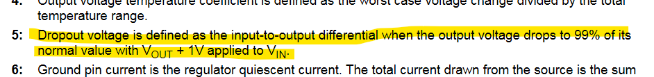
Reading between the lines, I'm guessing they meant to define dropout as the minimum Vin-Vout level that results in 1% output voltage drop, with Vin being at least 1 V. That seems logical and reasonable. This is partly corroborated by the short definition of Dropout Voltage on page 5:
However, if you really need to rely on that spec, you should get explicit clarification from Microchip.
Humans make mistakes. Datasheets are not immune to that, no less than the parts they describe, or your circuits you put those parts into. Keep in mind that this is a former Micrel part, so the datasheet must have gone thru significant re-do to put it into the standard Microchip format. If you are curious, go dig up the original Micrel datasheet. Then you can see if this error was there all along and nobody at Microchip noticed, or it got introduced by all the edits of the re-formatting process.
In general, I find Microchip datasheets more clear than most, and they usually specify the parameters you actually care about. However, they aren't perfect. I've found some worse errors than this one over the years. If you are feeling charitable, send a message to Microchip reporting this inconsistency. I have found that they do actually address such errors in future versions.
Here is another issue I noticed when reading your question:
drop-out voltage for the MIC29303WT as 80mV to 175mV MAX for an output current of 100mA. Moving to the next listed output current, 1.5A, we see 220mV of drop-out.
No, that's not what the datasheet says. From Table 1-1, "Electrical Characteristics" on page 5:
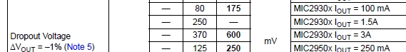
The three columns in the middle are labeled "Min", "Typ", and "Max". The top three lines apply to your part. I included the bottom line only so that the full description in the left column was visible.
This is giving you only two real data points.
- Line 1: At 100 mA output, the dropout can be as high as 175 mV.
- Line 3: At 3 A output, the dropout can be as high as 600 mV.
That's it. Line 2 contains no real actionable data at all. It basically says:
At 1.5 A output, the dropout is usually around 250 mV. Maybe. On a good day. If it's more and your circuit doesn't work, don't come crying to us. As Dirty Harry would say, "Do you feel lucky? Well do ya, punk!?"
So what excactly can you count on at 1.5 A? The absolute safe answer is that dropout won't exceed 600 mV. However, you have a strong hint that it will be less even under worst can conditions. 250 mv is the typical value. That means that you're about as likely to end up with more than 250 mV as less than 250 mV. How much more? See Dirty Harry for the answer.
1 comment thread
I just happened to re-read this question, and I now think I see better what Microchip was trying to say here:

On closer examination, I think this is actually correct but badly worded. I believe it should be interpreted as:
Dropout voltage is defined as the input-to-output differential when the output voltage drops to 99% of its normal value, compared to when VOUT + 1V is applied to VIN-.
1 comment thread

1 comment thread