Comments on How can I debug, (and eventually fix) this Roomba PCB?
Post
How can I debug, (and eventually fix) this Roomba PCB? [closed]
Closed as off topic by Nick Alexeev on Dec 10, 2020 at 19:21
This question is not within the scope of Electrical Engineering.
This question was closed; new answers can no longer be added. Users with the reopen privilege may vote to reopen this question if it has been improved or closed incorrectly.
I've got a broken roomba, I've tried new batteries and a working charger.
The charger is supposed to output 20V-24W when the roomba is plugged in.
the picture just shows how I'm measuring the power taken from the charger. I bought a Power Meter for this purpose. A functional roomba shows between 20-24W when the battery is charging, but mine shows between 0.8W-1.6W when the problem roomba is supposed to be charging.

My multi meter shows no connection from positive to positive pcb -> charger connector, but someone told me I could be seeing strange readings due to the Charging Mosfets. So now I'm stumped on how to continue debugging this. There is detected connection from Negative -> Negative.
Continuity tests on the PCB -> charger

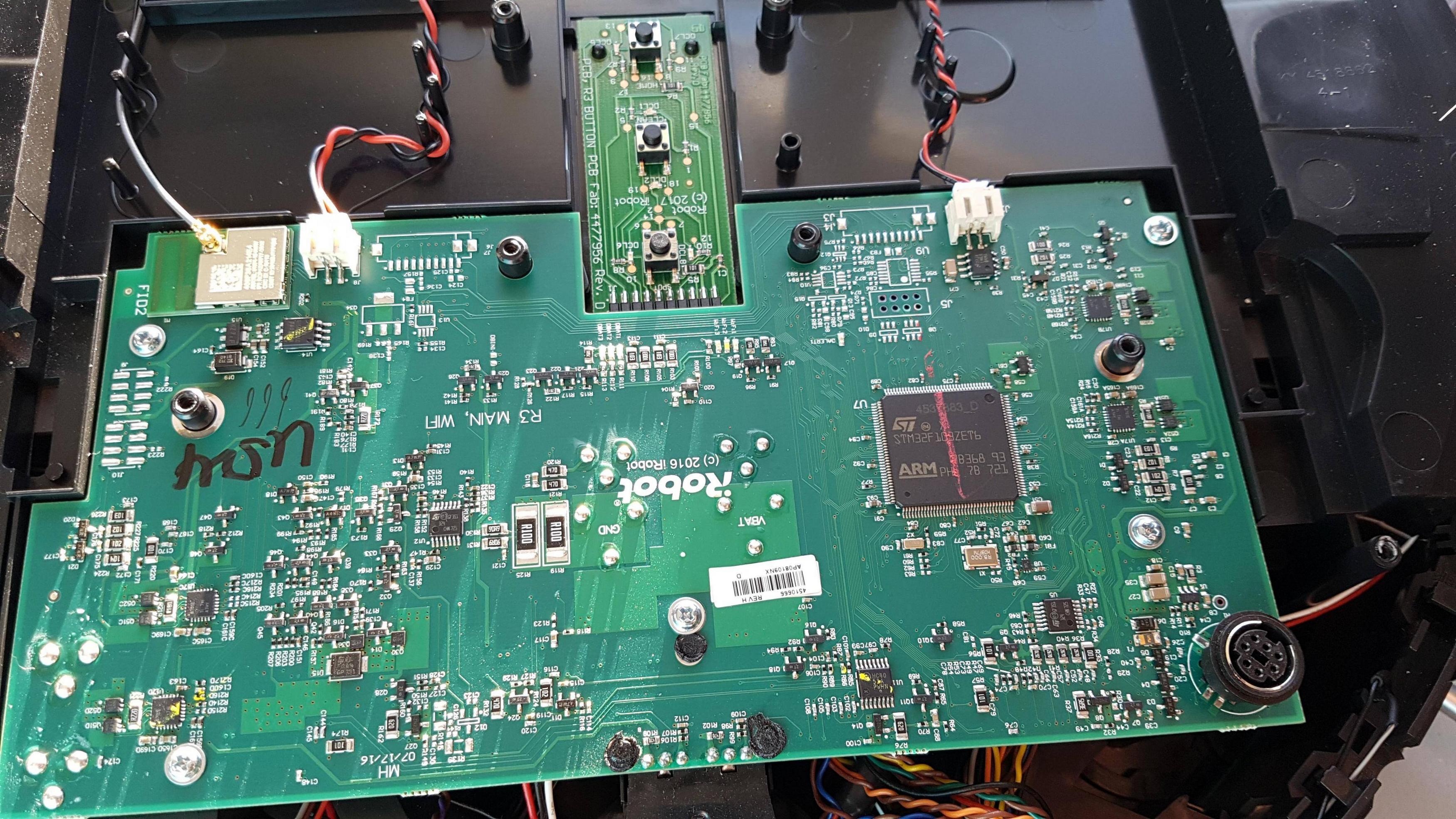
PCB Side 1
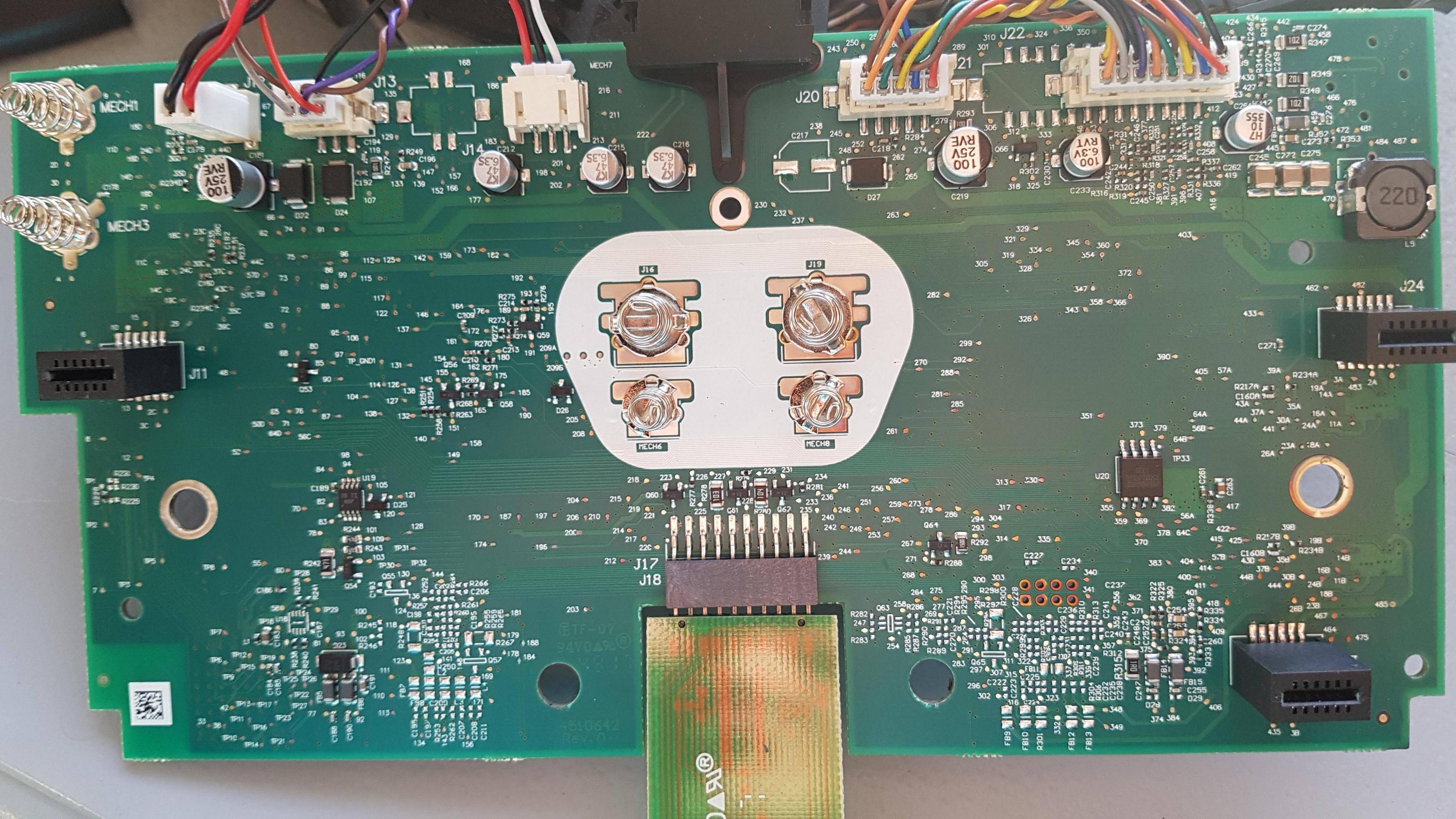
PCB Side 2
Additional info:
For testing I've disconnected everything except the Battery -> PCB and connector for PCB -> Charger.
The charger has 2 metal plates that attach to the roomba's 2 metal plates.
The Roomba was working at one time. I only know this based on the amount of dirt inside the roomba.
There is no issue with the charger or the battery. Both have tested in a working roomba
The roomba (model 690) uses a 14.4V Lithium Battery

1 comment thread