Comments on Driving ADC with opamp with large rails
Post
Is the risk too great?
That depends on parameters you haven't told us. How cost-sensitive is this product? What is the reliability expectation of the users? How mission-critical is its usage?
For example, if this were a toy, I'd say screw it and look for a way to not even buffer the signal in the first place. If this is sensing the temperature to control cooling pumps in a nuclear power plant, I'd not only follow every datasheet spec to the letter, but also add some margin, and then add redundant units anyway.
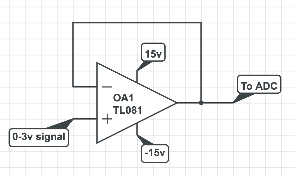
Let's say this is an industrial product where a few cents extra cost doesn't matter much, and you want reasonable robustness to protect your reputation. As others have said, put a resistor between the opamp output and the A/D input. Then take the feedback from the A/D side of the resistor. That makes the opamp produce whatever voltage is necessary on its end so that you get the desired voltage on the A/D end.
However, there is more to it than that. Just adding the resistor can lead to instability. To address that, add a feedback capacitor directly around the opamp:
The value of R1 was chosen to limit the A/D input current to 5 mA. The worst case is when the opamp drives its output all the way to -15 V. (15 V)/(5 mA) = 3 kΩ.
I picked the 47 pF value out of the air. This is hard to predict. Perhaps no additional capacitance is needed at all. I would put the pads on the board, then find the appropriate value by experimentation. I'd probably use twice whatever the largest value was at which I saw oscillation.
The drawback of making C1 too large is that the response slows down. If you don't need particularly fast response, you can be more aggressive with C1 to err on the side of stability.
1. why may the modest resistor inside the loop lead to instability? and 2. (probably related) could you explain how the cap solve this problem
The resistor together with whatever load may be on its right end can cause a phase shift. Even a little parasitic capacitance is enough to cause a measurable phase lag. That extra phase lag in the feedback path can cause the system to oscillate, depending on how close to the stability limit the opamp was trimmed for in the first place.
C1 adds feedback at high frequencies without any additional phase shift. It therefore increases stability at the expense of overall step response time. Another way to think about it is that since it directly feeds back high frequencies, it reduces the overall loop gain at those high frequencies. With less gain, the feedback, with its lag, matters less.
C1 is sometimes referred to as a compensation capacitor. This comes from compensating the overall feedback loop, which is one of the terms used in control theory to achieve stable systems.

1 comment thread