Comments on CAN Bus - Internal Oscillator
Parent
CAN Bus - Internal Oscillator
Every time I needed CAN, I had just put external crystal and didn't think about it after that. It worked fine.
I am wondering however whether the precisions of MCU internal oscillator is sufficient for up to 1Mbit/s and could I perhaps prove that on paper.
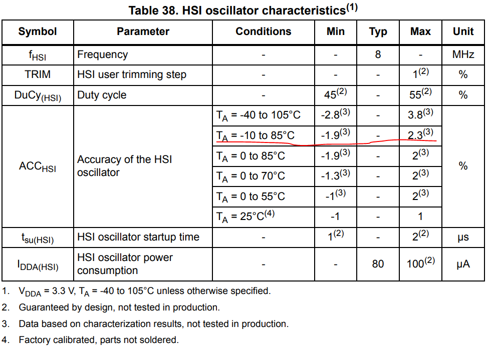
Internal Clock Specification
PLL Specification
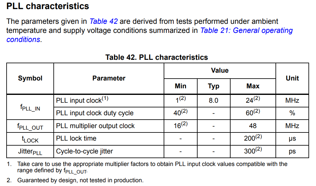
The desired frequency at the PLL's output should be 48 MHz.
I've read the above-given data that the internal clock before going to the PLL could be anywhere between 7.848 and 8.184 MHz. I would ignore the PLL's jitter because it's in the ps range and it shouldn't matter much.
Firstly, am I correct in assuming that the PLL's output should then be anywhere between 47.088 and 49.104 MHz?
CAN Peripheral inside of the MCU is being connected directly to the 48MHz clocked bus and derives the output baud rate based on the value of the PRESCALER register.
If we assume a perfect prescaler then the clock supplying the CAN should be in the range of 981kHz to 1023kHz. Let's say that we want to cover max. frequency of 1MBit/s on the bus, which is 1000ns(in other words, the minimum time between 2 consecutive bits). Due to the error of the internal MCU clock, my period should be anywhere between 977ns and 1019ns which given the eye diagram of the CAN that I've seen shouldn't be a problem.
Is my logic right? Basically every resource I've found online claims "You have CAN! Better by external crystal!"
The calculation above actually has quite a decent margin of error if valid.
What's the catch? Is everyone being paranoid, have I missed something or the manufacturing process of the MCU is not that reliable so I would end up having 70% of devices working and 30% not for a "mysterious" reason :)
Post
CAN is asynchronous and, if you receive a string of consecutive zeros, the UART mechanism that turns raw CAN data into "a byte" might have to wait a great deal longer than 1 bit of data before it can re-sync.
If data is coming 101010101010 then that's great but, if data is 010000000010 then you have to freewheel across all those zeros and still be able to reliably detect the next 1 without over-counting the number of steady bits you have received in the interim period.
By the way, 1 Mbps is a maximum frequency of 500 kHz because there are two symbol slots in one cycle.

0 comment threads