Comments on Low-frequency PWM-controlled Mosfet heater circuit
Post
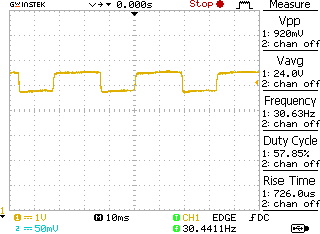
Low-frequency PWM-controlled Mosfet heater circuit
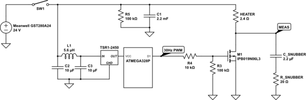
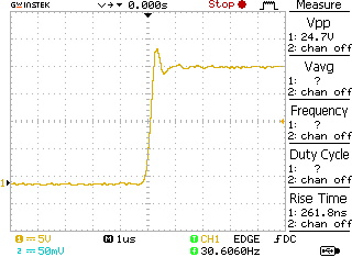
The circuit above is used to control a 240W ceramic heater by means of a PWM signal at 30Hz, generated by a microcontroller, with 5V logic. The input is a standard 280W AC-DC external power adapter, the Meanwell GST280A24.The C1 is a large electrolytic capacitor, 2200 uF, with 35V maximum voltage, placed close to the load. This capacitor has a maximum ripple current of 2,06A @ 100 KHz. The voltage signal measured in the MEAS node is very clean, there are no spikes or other strange behaviour. On the other hand the 24V line is showing a 880 mV voltage drop everytime the mosfet is energized: there are no spikes but the 24V line just goes down, in a square wave manner, by 0,8V. The overall system works fine, but I have doubts in terms of reliability over time. First of all, turn on behaviour when SW1 is closed: the microcontroller is programmed for a soft start of the Mosfet M1 and does not immediately powers the mosfet for the first 2-3 seconds. I measured the inrush current to be sure of not trepassing the power adapter limits (120A). It looks that I have a voltage rise from 0 to 24V in circa 5ms. That, giving the 2200 uF of input capacitance, gives 18A of inrush current. The second question is the switching behaviour of the mosfet. I voluntary put a huge gate resistor to slow down the mosfet turn on. I want at all cost to avoid ringing and possible EMI issues (this circuit needs to meet the EN 55011). Do you see any problems in switching the mosfet so slowly? When I measure at MEAS, I get a nice square wave, a bit rounded in the top part. Do you see any flaws in this circuit at all?
Dear Olin, thank you, you are a reference for all of us.
The C1 was put there for to reasons. One is dampening the resonance of input capacitance with wire inductance - I got 1.5 meters wires from the power adapter to the DC connector - which could lead to potentially destructive outcome. The other is to help the hungry heater keeping is current requirements. I did try to eliminate C1 and substitute it with a ceramic capacitor of 20 uF with low ESR and I ended up blewing up the Tracopower, the micro and a bunch of other stuff. I simulated it and I got a 42V resonance peak, which almost completely disappears using a large C1 with high ESR instead. R5 is there to empty the big fat C1 cap when power is off. I verified and a small voltage of some volts keeps staying there for long time after power is removed.
Regarding Mosfet switching, here they come the scope printouts for the MEAS probe node. With an R4 of 10 kOhm:
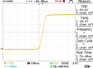
With an R4 of 10 Ohm
There you see the mosfet ringing. With R4 at 10 kOhm the mosfet is running cool and nice. Switching takes approx. 100us, is this really a problem?
Regarding the 800 mV drop, it becomes 900 mV without C1. This was measured directly on the DC input. There are 10cm wires from the DC input connector to the control card.
I will try to add the decoupling caps as you suggested. What should I add in total?
- A bunch of small ceramic capacitors in parallel, between 24V and GND, close to the load: 10uF, 1uF and 100pF
- A small 100pF capacitor between the Mosfet drain and GND

1 comment thread