Comments on How do I design a flyback converter? What are the basics I should know?
Parent
How do I design a flyback converter? What are the basics I should know?
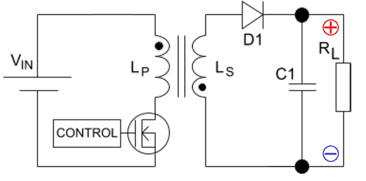
I need to design a simple flyback converter like this: -
I want to control duty cycle from another circuit such as an MCU but, I'm unsure how to proceed. My requirements are: -
- Input voltage
125 volts - Output voltage
500 volts - Load resistance is
10 kohm - Transformer turns ratio
1:1 - Primary/secondary inductance
1 mH - Operating frequency
100 kHz
Post
I see Andy has already given a detailed answer with a lot of good background on flyback converters. I'll answer the question more directly about how I would step thru this design if given these requirements.
For reference, here is the general flyback converter circuit copied from the question:
We are further told that:
Vin = 125 V
Vout = 500 V
Rl = 10 kΩ
transformer ratio = 1:1
Lp and Ls inductance = 1 mH
Switching frequency = 100 kHz
The first thing I would do is push back on some of these specs. I can accept that the client needs 500 V across a 10 kΩ load, and that 125 V is available. However, they shouldn't be telling me what transformer to use or what the switching frequency should be. Perhaps there are good reasons for those requirements, but I certainly wouldn't take them at face value. Clients will often over-spec such things and not be aware of the tradeoffs.
Let's say that after a conversation with the client, we find that they really do need to use this specific transformer (unlikely in the real world), and 100 kHz switching frequency (more likely to have a legitimate cause). I really don't like the transformer, since a 1:1 ratio is not ideal for boosting the voltage by 4x. However, we'll go with this anyway.
The next thing I want to know is what power level this is at. That puts the whole design in perspective at the high level. In this case, we know the voltage and load resistance, so the appropriate equation is:
W = V2 / Ω
where W is the power in Watts, V the EMF in Volts, and Ω the load resistance in Ohms.
(500 V)2 / (10 kΩ) = 25 W
OK, now we at least know what ballpark we're in. We're going to have to pay attention to heat dissipation, but shouldn't have to do anything out of the ordinary.
The next thing I want to know is how much primary current can we build up in a single switching cycle. The equation for current change in an inductor is:
A = V s / H
where A is the current change in Amps, V the applied voltage, s the time in seconds, and H the inductance in Henries.
(125 V)(10 µs)/(1 mH) = 1.25 A
I would immediately check this against the saturation limit of the primary, which is not given in this case. For sake of continuing, let's say that 1.25 A is comfortably below the saturation limit of the primary winding.
Then I want to know whether transferring 25 W is reasonably feasible. I really really want this to run in discontinuous mode. With 500 V output it's going to be essentially impossible to find a diode that has fast enough reverse recovery to make this design feasible. The current thru the diode needs to have stopped before the next input pulse start, which applies a large reverse voltage on the diode.
The energy in Joules stored in an inductor is:
J = ½ H A2
(1 mH)(1.25 A)2/2 = 781 µJ
Since we're switching at 100 kHz, the power transfer is (100 k)(781 µJ) = 78 W. This pretends the stored energy can magically discharge instantaneously to the output, but it gives a course-level sanity check. Since 78 W is considerably more than the 25 W we need, it's worth continuing with the more detailed calculations. If it was close to or less than 25 W, we would need to go back to the client and explain that something has to give.
Now let's find what the parameters of the input and output pulses will really be. First we find the energy that needs to be tranferred each cycle.
(25 W)/(100,000 cycles/s) = 250 µJ/cycle
From that we work the energy in an inductor equation backwards to find the primary current that causes 250 µJ.
A = sqrt(2 J / H)
sqrt(2 (250 µJ) / (1 mH)) = 707 mA
Now we find how long the switch needs to be on for to result in 707 mA primary current.
s = A H / V
(707 mA)(1 mH)/(125 V) = 5.66 µs
Since the secondary has the same inductance but there will be 4x the voltage decreasing the current during the output pulse, we know that the output will take ¼ as long, or 1.41 µs. That leaves 10 µs - 5.66 µs - 1.41 µs = 2.93 µs dead time between the end of the output pulse and the start of the next input pulse.
Of course there will be some losses, and the above numbers aren't as precise as they look. I usually do intermediate calculations with at least one extra digit to not add meaningful error to the eventual result. The losses will cause less energy to be transfered to the output than we assumed above. That in turn will cause the controller to lengthen the input pulses a bit to get the desired output voltage. Still, with roughly 60% charge, 15% discharge, and 25% off, there is comfortable margin.
So far all we've done is validate this thing is feasible, and found what the operating parameters will be. Now we have to do the actual circuit design.
The first thing I'd do there is replace the suggested FET switch with a bipolar transistor. At first glance, it might look like the switch only needs to work with 125 V on it, but it's actually far worse than that. During the discharge phase, there will be 500 V on the secondary. Since the transformer ratio is 1:1, there will also be 500 V on the primary. The top of the switch will see this 500 V added to the 125 V supply voltage, or 625 V. There will also be some kickback due to the leakage inductance. I'd want a transistor rated for 700 V at least.
In the 700 to 800 V range, bipolar transistors are going to have better characteristics, be more available, and cost less than FETs. Another advantage is that a FET at that voltage will need at least 12 V gate drive, whereas a BJT still only needs less than a volt on its base. The maybe 1 V or so saturation voltage of the BJT is of little consequence when starting with 125 V. A secondary advantage of a BJT is that it will deal better with the leakage kickback. The Miller capacitance will essentially limit the voltage slope a bit at the end of the charge time. FETs don't handle high dV/dt like that as gracefully.
Let's say we can find an NPN transistor with a gain of 20 at the voltage we require. I haven't actually looked, so this is an example. We found previously that the maximum current will be a bit over 700 mA, so let's use 750 mA as the design point. (750 mA)/20 = 38 mA. That's how much base drive we'll have to give the NPN low side switch. Here is one way to achieve that, assuming a 3.3 V digital signal from a microcontroller, and a 3.3 V supply capable of the extra 40 mA or so:
Q3 is the switch being driven. When the digital signal is low, Q1 is on, which drives base current into Q3 thru R1. Ideally, that is all that would be needed. However, we need Q3 to turn off quickly. Q2 turns on quickly when the digital signal goes high, which then quickly turns off Q3, even if Q1 is slow to turn off.
Note that Q1-2 and R1-3 are all jellybean parts without particularly stringent requirements. Even though Q3 is switching over 600 V, all these parts are operating at low voltage.
Another important design consideration is the output diode (D1). We already found that there will be a couple µs or so dead time between the end of the discharge phase and before the switch is turned on again. The major constraint is the voltage. When the supply is fully running, there will be 500 V on the right side of D1. During the charge phase, there will be -125 V on the left side, for a total of 625 V reverse voltage stress. Of course we want some margin. All together, we need a diode that can withstand 700 V, pass 750 mA, and has a reverse recovery time of 2 µs.
Lastly, we look at what requirements are on the capacitor. Obviously it needs to handle 500 V minimum. We weren't given any ripple spec, but let's say that the 100 kHz ripple should not exceed 1 V. The equation for voltage change on a capacitor is
V = A s / F
where F is the capacitance in Farads. Rearranged to find the capacitance, it becomes
F = A s / V
With 500 V on 10 kΩ, the output current is 50 mA. The minimum capacitance is therefore
(50 mA)(10 µs)/(1 V) = 500 nF
At ½ µF and 550 V, that's going to be a rather substantial and expensive capacitor. This is where I'd go back to the client and find out how much ripple can really be tolerated.

0 comment threads