Post History
The reason the transistor is dying is because you didn't put a flyback diode across the relay coil. Relay coils have significant inductance. This means the current can't change instantly without t...
#2: Post edited
- <p>The reason the transistor is dying is because you didn't put a
- <i>flyback diode</i> across the relay coil.
- <p>Relay coils have significant inductance. This means the current can't
- change instantly without the voltage being infinite.
- <p>It takes voltage applied over time to change the current thru an
- inductor:
- <p> A = V s / H
- <p>Where A is the current change in Amps, V the applied voltage, s the
- time the voltage is applied in seconds, and H the inductance in Henries.
- <p>This can be flipped around to find how high a voltage must be applied
- over a specific time for a specific inductance:
- <p> V = A H / s
- <p>After the relay has been on for a while, the coil current will be 63
- mA. Let's say the transistor turns off over 1 µs (a long time for
- such a transistor), and that the relay coil inductance is 1 mH. (63 mA)(1
- mH)/(1 µs) = 63 V. Your transistor is rated for 40 V<sub>CE</sub>
- absolute maximum, so it would clearly be abused. And, that was assuming
- the rather long turn off time of 1 µs and that the applied voltage
would be steady during that time. Both of those are unrealistic.- <p>What really happens is that the voltage rises quickly to the point the
- transistor breaks down and allows some current anyway. This damages the
transistor each time the relay is switched off, eventually the point of- failure.
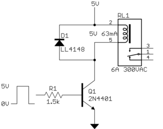
- <p>The solution is to add a diode across the relay coil:
- 
- <p>When the transistor turns off, even if instantaneously, the diode
- allows the coil current to keep flowing. The bottom of the coil will only
- go one diode drop above the 5 V supply level. This reverse voltage and
- the resistance of the coil cause the coil current to drop, which opens the
- relay.
- <p>The diode drop and the DC resistance of the coil are usually sufficient
- to drop the magnetic field and open the relay contact in about the time it
- takes the contacts to move, or less.
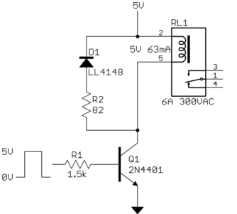
- <p>For applications where speed is important, an additional resistance can
- be added in series with the diode:
- 
- <p>This causes a higher initial reverse voltage across the coil, reducing
- its current, and thereby its magnetic field, more quickly. Note that the
- reverse voltage caused by the coil is still known and limited. We know
- that the coil current never exceeds 63 mA, so the voltage across the
- resitor will not exceed (63 mA)(82 Ω) = 5.2 V. In this example,
- right after switch off, the collector voltage of the transistor will be
- about 10.9 V. This comes from the 5 V the top of the relay coil is being
- held at, 700 mV for the voltage across the diode, and 5.2 V across R2.
- Since the transistor is rated for 40 V, this is well within spec.
- <p>The reason the transistor is dying is because you didn't put a
- <i>flyback diode</i> across the relay coil.
- <p>Relay coils have significant inductance. This means the current can't
- change instantly without the voltage being infinite.
- <p>It takes voltage applied over time to change the current thru an
- inductor:
- <p> A = V s / H
- <p>Where A is the current change in Amps, V the applied voltage, s the
- time the voltage is applied in seconds, and H the inductance in Henries.
- <p>This can be flipped around to find how high a voltage must be applied
- over a specific time for a specific inductance:
- <p> V = A H / s
- <p>After the relay has been on for a while, the coil current will be 63
- mA. Let's say the transistor turns off over 1 µs (a long time for
- such a transistor), and that the relay coil inductance is 1 mH. (63 mA)(1
- mH)/(1 µs) = 63 V. Your transistor is rated for 40 V<sub>CE</sub>
- absolute maximum, so it would clearly be abused. And, that was assuming
- the rather long turn off time of 1 µs and that the applied voltage
- would be steady during that time. Both of those assumptions are unrealistic.
- <p>What really happens is that the voltage rises quickly to the point the
- transistor breaks down and allows some current anyway. This damages the
- transistor each time the relay is switched off, eventually to the point of
- failure.
- <p>The solution is to add a diode across the relay coil:
- 
- <p>When the transistor turns off, even if instantaneously, the diode
- allows the coil current to keep flowing. The bottom of the coil will only
- go one diode drop above the 5 V supply level. This reverse voltage and
- the resistance of the coil cause the coil current to drop, which opens the
- relay.
- <p>The diode drop and the DC resistance of the coil are usually sufficient
- to drop the magnetic field and open the relay contact in about the time it
- takes the contacts to move, or less.
- <p>For applications where speed is important, an additional resistance can
- be added in series with the diode:
- 
- <p>This causes a higher initial reverse voltage across the coil, reducing
- its current, and thereby its magnetic field, more quickly. Note that the
- reverse voltage caused by the coil is still known and limited. We know
- that the coil current never exceeds 63 mA, so the voltage across the
- resitor will not exceed (63 mA)(82 Ω) = 5.2 V. In this example,
- right after switch off, the collector voltage of the transistor will be
- about 10.9 V. This comes from the 5 V the top of the relay coil is being
- held at, 700 mV for the voltage across the diode, and 5.2 V across R2.
- Since the transistor is rated for 40 V, this is well within spec.
#1: Initial revision
<p>The reason the transistor is dying is because you didn't put a <i>flyback diode</i> across the relay coil. <p>Relay coils have significant inductance. This means the current can't change instantly without the voltage being infinite. <p>It takes voltage applied over time to change the current thru an inductor: <p> A = V s / H <p>Where A is the current change in Amps, V the applied voltage, s the time the voltage is applied in seconds, and H the inductance in Henries. <p>This can be flipped around to find how high a voltage must be applied over a specific time for a specific inductance: <p> V = A H / s <p>After the relay has been on for a while, the coil current will be 63 mA. Let's say the transistor turns off over 1 µs (a long time for such a transistor), and that the relay coil inductance is 1 mH. (63 mA)(1 mH)/(1 µs) = 63 V. Your transistor is rated for 40 V<sub>CE</sub> absolute maximum, so it would clearly be abused. And, that was assuming the rather long turn off time of 1 µs and that the applied voltage would be steady during that time. Both of those are unrealistic. <p>What really happens is that the voltage rises quickly to the point the transistor breaks down and allows some current anyway. This damages the transistor each time the relay is switched off, eventually the point of failure. <p>The solution is to add a diode across the relay coil:  <p>When the transistor turns off, even if instantaneously, the diode allows the coil current to keep flowing. The bottom of the coil will only go one diode drop above the 5 V supply level. This reverse voltage and the resistance of the coil cause the coil current to drop, which opens the relay. <p>The diode drop and the DC resistance of the coil are usually sufficient to drop the magnetic field and open the relay contact in about the time it takes the contacts to move, or less. <p>For applications where speed is important, an additional resistance can be added in series with the diode:  <p>This causes a higher initial reverse voltage across the coil, reducing its current, and thereby its magnetic field, more quickly. Note that the reverse voltage caused by the coil is still known and limited. We know that the coil current never exceeds 63 mA, so the voltage across the resitor will not exceed (63 mA)(82 Ω) = 5.2 V. In this example, right after switch off, the collector voltage of the transistor will be about 10.9 V. This comes from the 5 V the top of the relay coil is being held at, 700 mV for the voltage across the diode, and 5.2 V across R2. Since the transistor is rated for 40 V, this is well within spec.


