Post History
I'm adding to Olin's answer with a little bit of theory (from the standpoint of an EE) and I'm also showing a 2nd order IIR filter. The 2nd order filter is based on cascading two 1st order stages w...
#3: Post edited
by
 Andy aka
·
2020-06-23T11:07:49Z (almost 5 years ago)
Andy aka
·
2020-06-23T11:07:49Z (almost 5 years ago)
Being an occasional coder and as much interested in "why" as "how" I'm adding to Olin's answer with a little bit of theory (from the standpoint of an EE) and showing a 2nd order version of the 1st order (equivalent to and RC) low pass filter.All these filters are IIR types and are the same as Olin discusses in his answer: -- 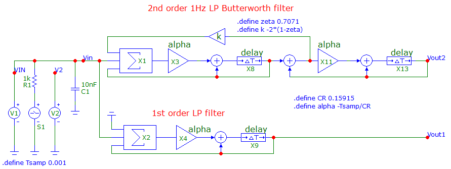
- There are two filters in the above diagram: -
- - 1st order 1 Hz low pass filter
- - 2nd order 1 Hz low pass filter
- The 2nd order low pass filter has been adjusted to give a Butterworth response i.e. maximally flat in the pass band. The sample rate is 1 kHz.
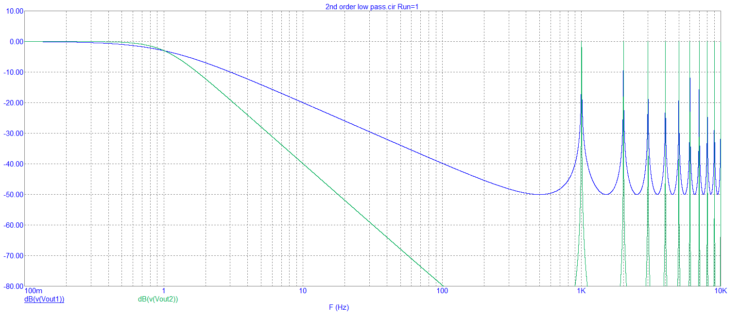
- The AC responses are: -
- 
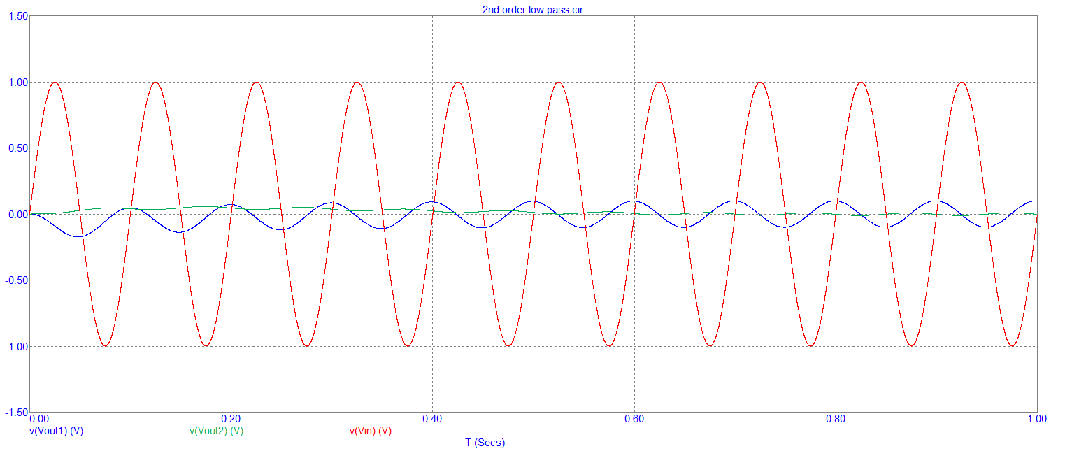
- And the 10 Hz signal input transient responses are: -
- 
- Several things are defined in the "schematic": -
- - Tsamp is the sample time (set to 1 ms)
- - CR is the capacitor-resistor time constant (set to 0.15915)
- - This CR time is for a 1 Hz low pass filter because: -
- $$F_C = \dfrac{1}{2\pi CR} = 1 \text{ Hz}$$
- Those definitions suit both filters and, for the 2nd order filter, there is a definition that sets the damping: -
- - zeta (damping ratio or \$\zeta\$) is set to 0.7071 (classical Butterworth response)
- - k is the feedback factor and equals \$-2\cdot(1 - \zeta)\$
This is aimed at the occasional coder who knows about analogue circuits and wondered how a simple CR circuit can be transformed into the z-plane. Here's the equivalent analogue circuit: -- 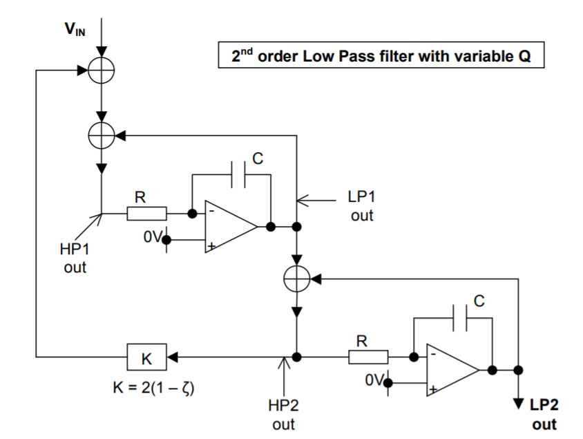
- Maybe of interest is that the HP2 node is also a band-pass output.
- -----
- If we change zeta and concentrate on the 2nd order output we get: -
- I'm adding to Olin's answer with a little bit of theory (from the standpoint of an EE) and I'm also showing a 2nd order IIR filter. The 2nd order filter is based on cascading two 1st order stages with an additional feedback loop to control Q factor (or \$\zeta\$).
- Both these filters are IIR types of the type discussed by Olin: -
- 
- There are two filters in the above diagram: -
- - 1st order 1 Hz low pass filter
- - 2nd order 1 Hz low pass filter
- The 2nd order low pass filter has been adjusted to give a Butterworth response i.e. maximally flat in the pass band. The sample rate is 1 kHz.
- The AC responses are: -
- 
- And the 10 Hz signal input transient responses are: -
- 
- Several things are defined in the "schematic": -
- - Tsamp is the sample time (set to 1 ms)
- - CR is the capacitor-resistor time constant (set to 0.15915)
- - This CR time is for a 1 Hz low pass filter because: -
- $$F_C = \dfrac{1}{2\pi CR} = 1 \text{ Hz}$$
- Those definitions suit both filters and, for the 2nd order filter, there is a definition that sets the damping: -
- - zeta (damping ratio or \$\zeta\$) is set to 0.7071 (classical Butterworth response)
- - k is the feedback factor and equals \$-2\cdot(1 - \zeta)\$
- On the left of the schematic is: -
- - V1, an analogue voltage source to provide an input
- - V2, a square wave source for sampling V1
- - S1, does the sampling for transient analysis
- This answer is aimed at the occasional coder who knows about analogue circuits and wondered how a simple CR circuit can be transformed into the z-plane.
- Here's the equivalent analogue circuit: -
- 
- Maybe of interest is that the HP2 node is also a band-pass output.
- -----
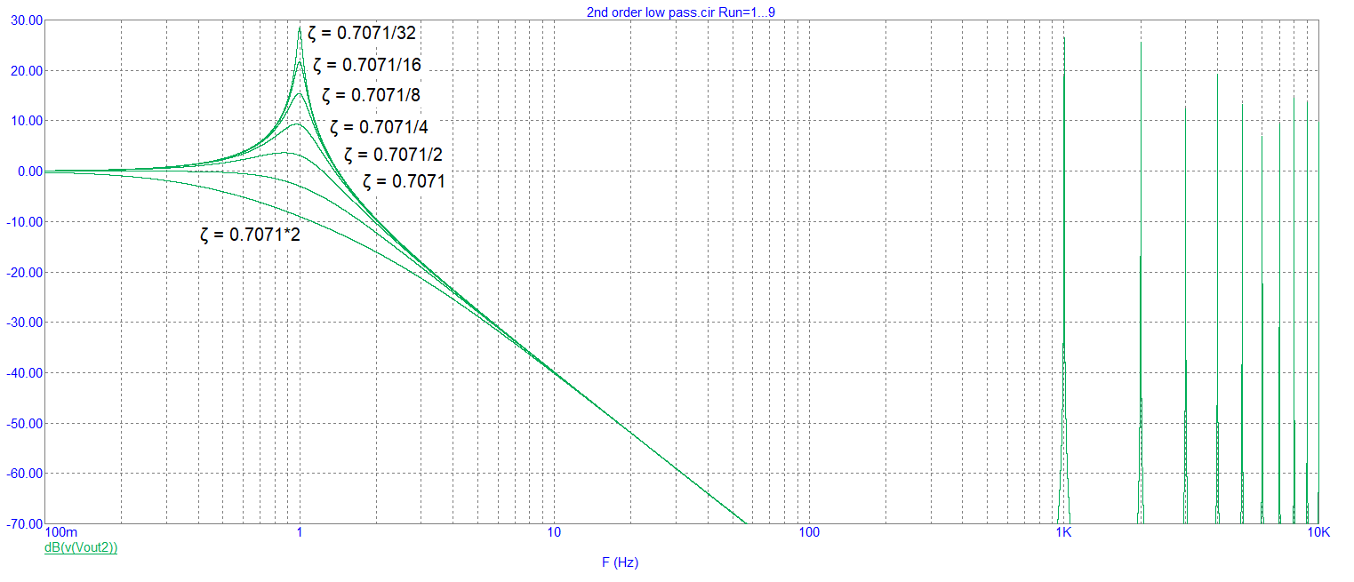
- If we change zeta and concentrate on the 2nd order output we get: -
- 
- Which is "as expected" for this type of filter.
#2: Post edited
by
Andy aka
·
2020-06-23T10:48:16Z (almost 5 years ago)
Being an occasional coder and as much interested in "why" as "how" I'm adding to Olin's answer with a little bit of theory (from the standpoint of an EE) and showing a 2nd order version of the 1st order (equivalent to and RC) low pass filter: -- There are two filters in the above diagram: -
- - 1st order 1 Hz low pass filter
- - 2nd order 1 Hz low pass filter
- The 2nd order low pass filter has been adjusted to give a Butterworth response i.e. maximally flat in the pass band. The sample rate is 1 kHz.
- The AC responses are: -
- 
- And the 10 Hz signal input transient responses are: -
- 
- Several things are defined in the "schematic": -
- - Tsamp is the sample time (set to 1 ms)
- - CR is the capacitor-resistor time constant (set to 0.15915)
- - This CR time is for a 1 Hz low pass filter because: -
- $$F_C = \dfrac{1}{2\pi CR} = 1 \text{ Hz}$$
- Those definitions suit both filters and, for the 2nd order filter, there is a definition that sets the damping: -
- - zeta (damping ratio or \$\zeta\$) is set to 0.7071 (classical Butterworth response)
- - k is the feedback factor and equals \$-2\cdot(1 - \zeta)\$
- This is aimed at the occasional coder who knows about analogue circuits and wondered how a simple CR circuit can be transformed into the z-plane. Here's the equivalent analogue circuit: -
- 
- Maybe of interest is that the HP2 node is also a band-pass output.
- -----
- If we change zeta and concentrate on the 2nd order output we get: -
- 
- Being an occasional coder and as much interested in "why" as "how" I'm adding to Olin's answer with a little bit of theory (from the standpoint of an EE) and showing a 2nd order version of the 1st order (equivalent to and RC) low pass filter.
- All these filters are IIR types and are the same as Olin discusses in his answer: -
- 
- There are two filters in the above diagram: -
- - 1st order 1 Hz low pass filter
- - 2nd order 1 Hz low pass filter
- The 2nd order low pass filter has been adjusted to give a Butterworth response i.e. maximally flat in the pass band. The sample rate is 1 kHz.
- The AC responses are: -
- 
- And the 10 Hz signal input transient responses are: -
- 
- Several things are defined in the "schematic": -
- - Tsamp is the sample time (set to 1 ms)
- - CR is the capacitor-resistor time constant (set to 0.15915)
- - This CR time is for a 1 Hz low pass filter because: -
- $$F_C = \dfrac{1}{2\pi CR} = 1 \text{ Hz}$$
- Those definitions suit both filters and, for the 2nd order filter, there is a definition that sets the damping: -
- - zeta (damping ratio or \$\zeta\$) is set to 0.7071 (classical Butterworth response)
- - k is the feedback factor and equals \$-2\cdot(1 - \zeta)\$
- This is aimed at the occasional coder who knows about analogue circuits and wondered how a simple CR circuit can be transformed into the z-plane. Here's the equivalent analogue circuit: -
- 
- Maybe of interest is that the HP2 node is also a band-pass output.
- -----
- If we change zeta and concentrate on the 2nd order output we get: -
- 
#1: Initial revision
by
Andy aka
·
2020-06-23T10:43:53Z (almost 5 years ago)
Being an occasional coder and as much interested in "why" as "how" I'm adding to Olin's answer with a little bit of theory (from the standpoint of an EE) and showing a 2nd order version of the 1st order (equivalent to and RC) low pass filter: -

There are two filters in the above diagram: -
- 1st order 1 Hz low pass filter
- 2nd order 1 Hz low pass filter
The 2nd order low pass filter has been adjusted to give a Butterworth response i.e. maximally flat in the pass band. The sample rate is 1 kHz.
The AC responses are: -

And the 10 Hz signal input transient responses are: -

Several things are defined in the "schematic": -
- Tsamp is the sample time (set to 1 ms)
- CR is the capacitor-resistor time constant (set to 0.15915)
- This CR time is for a 1 Hz low pass filter because: -
$$F_C = \dfrac{1}{2\pi CR} = 1 \text{ Hz}$$
Those definitions suit both filters and, for the 2nd order filter, there is a definition that sets the damping: -
- zeta (damping ratio or \$\zeta\$) is set to 0.7071 (classical Butterworth response)
- k is the feedback factor and equals \$-2\cdot(1 - \zeta)\$
This is aimed at the occasional coder who knows about analogue circuits and wondered how a simple CR circuit can be transformed into the z-plane. Here's the equivalent analogue circuit: -

Maybe of interest is that the HP2 node is also a band-pass output.
-----
If we change zeta and concentrate on the 2nd order output we get: -
