Post History
To avoid shoot-through you should ensure that the active-low P-channel MOSFET gate drive voltage never overlaps with the active-high N-channel MOSFET gate drive voltage. With an inverter driving th...
#5: Post edited
by
 Andy aka
·
2020-07-21T08:34:24Z (almost 5 years ago)
Andy aka
·
2020-07-21T08:34:24Z (almost 5 years ago)
- To avoid shoot-through you should ensure that the active-low P-channel MOSFET gate drive voltage never overlaps with the active-high N-channel MOSFET gate drive voltage. With an inverter driving the N-channel MOSFET's gate, the increased propagation delay can often mean that the N-channel device remains "ON" for a small period of time whilst the P-channel MOSFET is activating. This leads to a current pulse from the power supply that flows through both MOSFETs. The pulse can be high in magnitude and can significantly disrupt the stability of the power rails.
- -----
- I have used Schmitt trigger logic gates connected like this: -
- 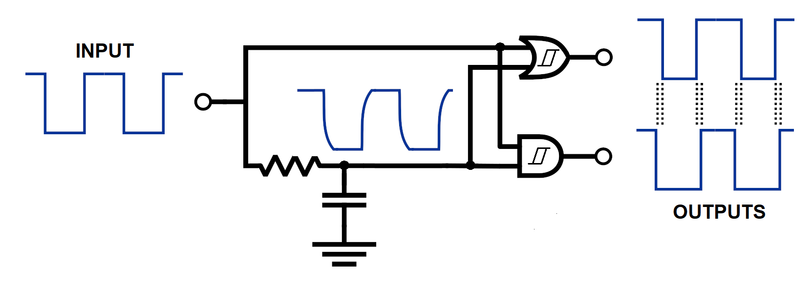
- The RC network is chosen to deliver a small delay to one of the inputs of both gates. This ensures that when the input goes high, the output from the AND gate remains low for a small time period approximately equal to RC. The OR gate ensures that when the input goes low, its output remains high for the same small time period.
- This circuit works for a P channel high-side MOSFET and an N channel low-side MOSFET. In other words the OR gate output is active-low and the AND gate output is active-high. This ensures that there is no overlap in the gate drive signals and, that means that shoot-through possibilities are remote if not insignificant.
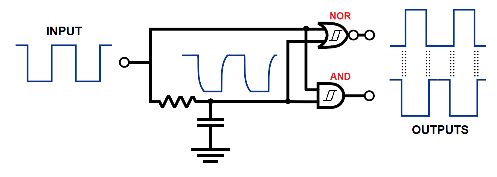
If you were using a high-side N channel MOSFET (with the appropriate above-rail driver) you would use a NOR gate in place or the OR.
- To avoid shoot-through you should ensure that the active-low P-channel MOSFET gate drive voltage never overlaps with the active-high N-channel MOSFET gate drive voltage. With an inverter driving the N-channel MOSFET's gate, the increased propagation delay can often mean that the N-channel device remains "ON" for a small period of time whilst the P-channel MOSFET is activating. This leads to a current pulse from the power supply that flows through both MOSFETs. The pulse can be high in magnitude and can significantly disrupt the stability of the power rails.
- -----
- I have used Schmitt trigger logic gates connected like this: -
- 
- The RC network is chosen to deliver a small delay to one of the inputs of both gates. This ensures that when the input goes high, the output from the AND gate remains low for a small time period approximately equal to RC. The OR gate ensures that when the input goes low, its output remains high for the same small time period.
- This circuit works for a P channel high-side MOSFET and an N channel low-side MOSFET. In other words the OR gate output is active-low and the AND gate output is active-high. This ensures that there is no overlap in the gate drive signals and, that means that shoot-through possibilities are remote if not insignificant.
- If you were using a high-side N channel MOSFET (with the appropriate above-rail driver) you would use a NOR gate in place or the OR: -
- 
#4: Post edited
by
Andy aka
·
2020-06-26T12:31:25Z (almost 5 years ago)
- I have used Schmitt trigger logic gates connected like this: -
- 
- The RC network is chosen to deliver a small delay to one of the inputs of both gates. This ensures that when the input goes high, the output from the AND gate remains low for a small time period approximately equal to RC. The OR gate ensures that when the input goes low, its output remains high for the same small time period.
- This circuit works for a P channel high-side MOSFET and an N channel low-side MOSFET. In other words the OR gate output is active-low and the AND gate output is active-high. This ensures that there is no overlap in the gate drive signals and, that means that shoot-through possibilities are remote if not insignificant.
- If you were using a high-side N channel MOSFET (with the appropriate above-rail driver) you would use a NOR gate in place or the OR.
- To avoid shoot-through you should ensure that the active-low P-channel MOSFET gate drive voltage never overlaps with the active-high N-channel MOSFET gate drive voltage. With an inverter driving the N-channel MOSFET's gate, the increased propagation delay can often mean that the N-channel device remains "ON" for a small period of time whilst the P-channel MOSFET is activating. This leads to a current pulse from the power supply that flows through both MOSFETs. The pulse can be high in magnitude and can significantly disrupt the stability of the power rails.
- -----
- I have used Schmitt trigger logic gates connected like this: -
- 
- The RC network is chosen to deliver a small delay to one of the inputs of both gates. This ensures that when the input goes high, the output from the AND gate remains low for a small time period approximately equal to RC. The OR gate ensures that when the input goes low, its output remains high for the same small time period.
- This circuit works for a P channel high-side MOSFET and an N channel low-side MOSFET. In other words the OR gate output is active-low and the AND gate output is active-high. This ensures that there is no overlap in the gate drive signals and, that means that shoot-through possibilities are remote if not insignificant.
- If you were using a high-side N channel MOSFET (with the appropriate above-rail driver) you would use a NOR gate in place or the OR.
#3: Post edited
by
Andy aka
·
2020-06-26T12:22:57Z (almost 5 years ago)
- I have used Schmitt trigger logic gates connected like this: -
- 
- The RC network is chosen to deliver a small delay to one of the inputs of both gates. This ensures that when the input goes high, the output from the AND gate remains low for a small time period approximately equal to RC. The OR gate ensures that when the input goes low, its output remains high for the same small time period.
This circuit works for a P channel high-side MOSFET and an N channel low-side MOSFET. In other words the OR gate output is active-low and the AND gate output is active-high.- If you were using a high-side N channel MOSFET (with the appropriate above-rail driver) you would use a NOR gate in place or the OR.
- I have used Schmitt trigger logic gates connected like this: -
- 
- The RC network is chosen to deliver a small delay to one of the inputs of both gates. This ensures that when the input goes high, the output from the AND gate remains low for a small time period approximately equal to RC. The OR gate ensures that when the input goes low, its output remains high for the same small time period.
- This circuit works for a P channel high-side MOSFET and an N channel low-side MOSFET. In other words the OR gate output is active-low and the AND gate output is active-high. This ensures that there is no overlap in the gate drive signals and, that means that shoot-through possibilities are remote if not insignificant.
- If you were using a high-side N channel MOSFET (with the appropriate above-rail driver) you would use a NOR gate in place or the OR.
#2: Post edited
by
Andy aka
·
2020-06-26T11:32:59Z (almost 5 years ago)
- I have used Schmitt trigger logic gates connected like this: -
- 
- The RC network is chosen to deliver a small delay to one of the inputs of both gates. This ensures that when the input goes high, the output from the AND gate remains low for a small time period approximately equal to RC. The OR gate ensures that when the input goes low, its output remains high for the same small time period.
This circuit works for a P channel high-side MOSFET and an N channel low-side MOSFET. In other words the OR gate output is active-low and the AND gate output is active-high.
- I have used Schmitt trigger logic gates connected like this: -
- 
- The RC network is chosen to deliver a small delay to one of the inputs of both gates. This ensures that when the input goes high, the output from the AND gate remains low for a small time period approximately equal to RC. The OR gate ensures that when the input goes low, its output remains high for the same small time period.
- This circuit works for a P channel high-side MOSFET and an N channel low-side MOSFET. In other words the OR gate output is active-low and the AND gate output is active-high.
- If you were using a high-side N channel MOSFET (with the appropriate above-rail driver) you would use a NOR gate in place or the OR.
#1: Initial revision
by
Andy aka
·
2020-06-26T11:30:45Z (almost 5 years ago)
I have used Schmitt trigger logic gates connected like this: -  The RC network is chosen to deliver a small delay to one of the inputs of both gates. This ensures that when the input goes high, the output from the AND gate remains low for a small time period approximately equal to RC. The OR gate ensures that when the input goes low, its output remains high for the same small time period. This circuit works for a P channel high-side MOSFET and an N channel low-side MOSFET. In other words the OR gate output is active-low and the AND gate output is active-high.