1 answer
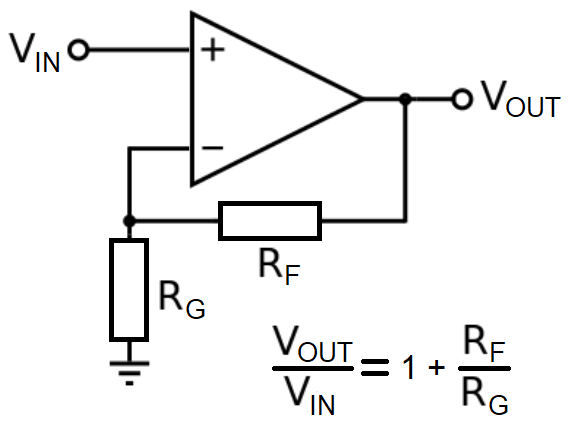
Input offset voltage $V_{OS}$
Your problem might be input offset voltage or $V_{OS}$. This can be several milli-volts and manifests as this modification to your original circuit (in red): -
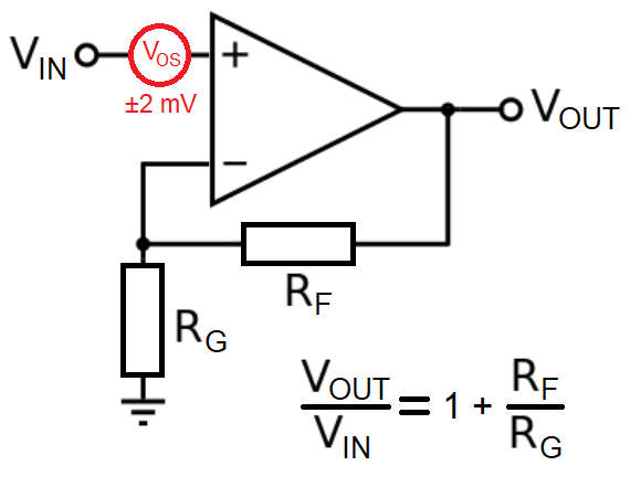
So, for an op-amp like the LM358 or LM324, you can expect a typical $V_{OS}$ of about 2 mV. This can add-to or subtract-from your 10 mV input signal. If it is subtractive then your effective input is now 8 mV and, with a gain of 101 you get an output voltage of 808 mV.
For AC signal amplification this isn't really a problem but, if you need DC accuracy, then you should choose a better op-amp. Your error limit might be 1% and, 1% of 10 mV is 100 μV so, if you need this accuracy, you should look for an op-amp with a $V_{OS}$ better than ±100 μV.
But, also be aware that $V_{OS}$ can drift with temperature. Take a device like the AD8605 (I'm choosing that because I know them like the back of my hand): -
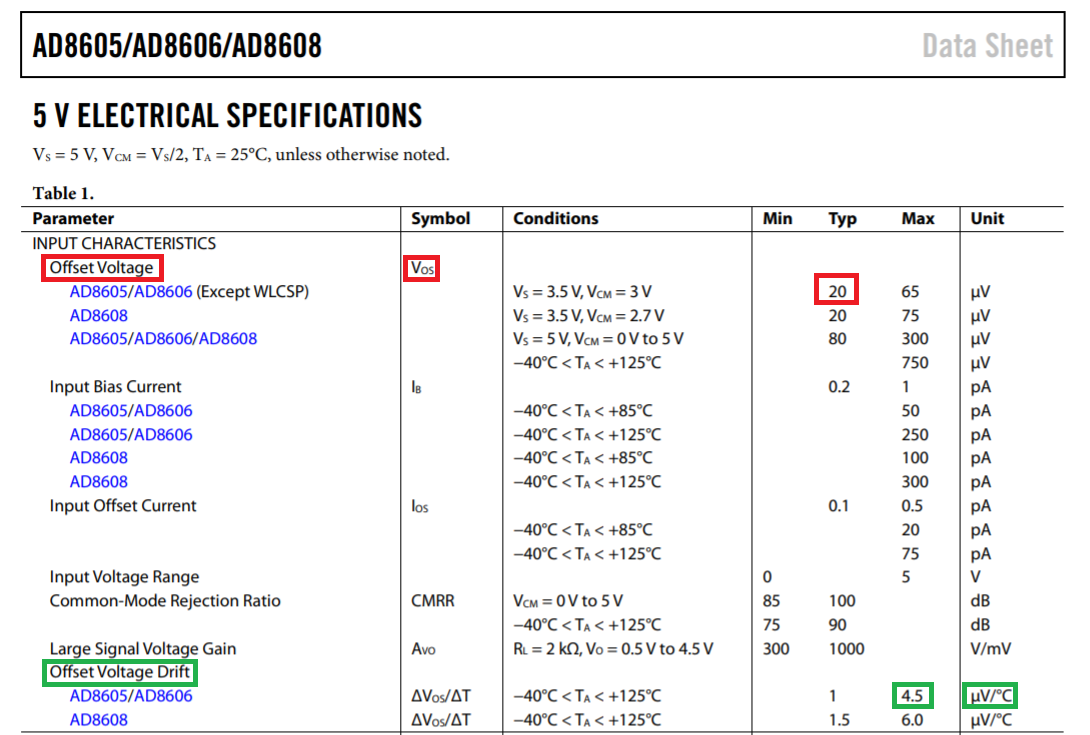
Highlighted in red is the typical $V_{OS}$ of ±20 μV but, at 25 °C it might be as high as ±65 μV. OK, ±65 μV might be OK for the error budget but, take a look at the number highlighted in green. This tells you how much that offset could drift with temperature.
So if your op-amp "sees" to a 10 °C change in temperature, you can add-on another 45 μV to your expected $V_{OS}$ and now the figure becomes: -
$$\boxed{65\text{ μV} + 45\text{ μV} = 110\text{ μV}}$$
If this is too-much you should choose a better op-amp.
Input currents $I_B$ and $I_{OS}$
So let's say you did choose a decent op-amp and expected to see an output voltage within 1.01 volts ± 10 mV but, this still didn't happen. The next problem to consider is input bias current ($I_B$).
$I_B$ flows from/into the op-amp inputs and can be commonly in the 1 to 100 nano amp range but, if you are using quite high-value op-amp resistors ($R_F$ and $R_G$), then that bias current multiplied by the effective parallel combination of $R_F$ and $R_G$ can "generate" a significant offset voltage.
$$\boxed{\text{That offset can be regarded as being in exactly the same position as }V_{OS}}$$
Using the LM324 as an example: -
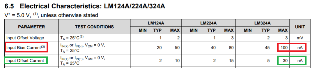
As you should be able to see (red box), the worst case input bias current is ±100 nA and, if this flows through a 10 kΩ resistor, the volt-drop would be ±0.001 volts. When multiplied by the circuit gain of 101, the output error becomes ±0.101 volts.
However, if you added a 10 kΩ resistor in series with the input signal as shown below, you do get an improvement: -
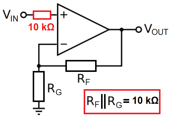
Look at the green box in the LM324 specification - it has an input offset current ($I_{OS}$) of 30 nA. This is the maximum difference between the bias currents of the two op-amp inputs and is called an offset because of this.
With the addition of the extra 10 kΩ resistor, the offset voltage created by the input bias currents are nearly cancelled but, they are not minimized to zero. In effect, we can now regard an input offset current of 30 nA flowing through the added 10 kΩ resistor and this, produces an offset voltage of 0.3 mV. Multiply this by the gain of 101 to get an output error of ±0.0303 volts.
Clearly, if we were looking for an error no greater than 1% of 1.01 volts on the output, we still haven't achieved this using an op-amp with similar bias currents as the LM324 so a better op-amp is needed.
All together now
Input bias currents ($I_B$ & $I_{OS}$) and input offset voltage ($V_{OS}$) do not work separately - they both occur together and are indistinguishable so, if need to accurately amplify small DC signals, you have to choose the appropriate op-amp.
0 comment threads

0 comment threads