Post History
Equivalent Circuit, 1:1 transformer Start by simplifying the circuit and change the transformer to a single inductor. This simplification ignores the benefits of isolation but, flyback converter t...
#20: Post edited
by
 Andy aka
·
2022-01-10T15:30:10Z (over 3 years ago)
Andy aka
·
2022-01-10T15:30:10Z (over 3 years ago)
- # Equivalent Circuit, 1:1 transformer
- Start by simplifying the circuit and change the transformer to a single inductor. This simplification ignores the benefits of isolation but, flyback converter theory is about transferring energy and not fundamentally about isolation: -
- 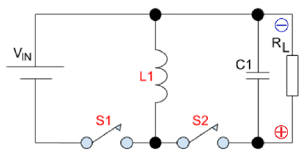
- We also don't need to worry about the output polarity being inverted because, when a transformer is used in the real circuit, isolation and correct DC polarity are delivered
- # The Operating mode, 1:1 transformer
- The circuit operates in either of two modes but, the voltage transfer equation is different for each mode. Therefore, you need to establish the operating mode before you can calculate duty cycle. The operating modes are: -
- - **DCM** (discontinuous conduction mode) - inductor current will fall to zero amps. Accommodates light to medium load currents. Duty cycle lower than **CCM**.
- - **CCM** (continuous conduction mode) - inductor current remains above zero amps. Accommodates medium to heavier load currents. Duty cycle higher than **DCM**.
- -----
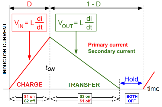
- **DCM** has three distinct phases per switching cycle; charge (red), transfer (green) and hold. The length of the hold-phase accommodates load current variations: -
- 
- -----
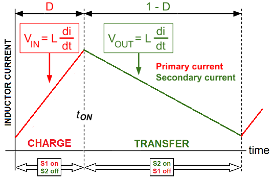
- **CCM** has just two phases; charge (red) and transfer (green). Load current changes are accommodated by the whole of the inductor current waveform rising or falling: -
- 
- **CCM and DCM summary**
- Only one mode will deliver 500 volts to the 10 kΩ load with \$V_{IN}\$, \$L\$ and \$F_{SW}\$ as specified.
- - Lighter loads are usually serviced in **DCM**
- - Heavier loads are usually serviced in **CCM**
- - **CCM** is a natural outcome when **DCM** can't service the heavier load
- - **DCM** is a natural outcome when **CCM** can't service the lighter load
- The next step is to decide which operating mode fulfills the requirements of the proposed design. To do this we consider the boundary condition.
- -----
- # Boundary condition, 1:1 transformer
- This is where **DCM** meets **CCM**; the inductor has delivered all it's energy to the output and the switching cycle restarts immediately. We then need to ask this hypothetical question: -
$$\color{red}{\boxed\{\large\text{At the boundary, is the load power sufficient to sustain \$V_{OUT}\$}}}$$- If the answer is yes, then we will operate in **DCM**. If the answer is no we will operate in **CCM**.
- **Boundary Power Transfer Analysis**
- 
- We need to find the input output relationship and duty cycle in the boundary condition. Simple analysis tells us: -
- $$\text{boundary condition }\Bigg\rvert\dfrac{V_O}{V_{IN}} = \dfrac{D}{1-D}\text{ and } D = \dfrac{V_O}{V_{IN}+V_O}\Bigg\rvert\text{ boundary condition}$$
- Calculate D using the values in the question: -
- $$D = \dfrac{V_O}{V_{IN}+V_O} = \dfrac{500}{125+500} = 0.8000$$
- This also delivers \$t_1\$ (time taken to charge the inductor): -
- $$t_1 = \dfrac{D}{F_{SW}} = \dfrac{0.8}{\text{100 kHz}} = \text{8 μs}$$
- # Calculating \$I_{PK}\$ in the boundary condition
- Using Faraday's equation for an inductor we know: -
- $$\boxed{V = L\cdot\dfrac{di}{dt}}$$
- - \$V = V_{IN}\$ = 125 volts
- - \$di = I_{PK}\$ (the peak current at the end of phase 1)
- - \$dt = t_1\$ = 8 μs
- - \$L\ =$ inductance (1 mH in this example)
- Hence:
- $$V_{IN} = L\cdot\dfrac{I_{PK}}{t_1}\therefore I_{PK} = \dfrac{t_1\cdot V_{IN}}{L} = \text{ 1.00 amps}$$
- # The stored energy (W) in boundary condition
- The inductor's stored energy (W) is found using this well-known formula: -
- $$\boxed{W = \dfrac{1}{2}\cdot L\cdot I_{PK}^2}$$
- If we plug the numbers in for current and inductance we get an energy figure of 500 μJ.
- # The power transfer in the boundary condition
- Inductor stored energy of 500 μJ is transferred to the load 100,000 times per second (\$F_{SW}\$).
- $$\color{red}{\boxed\{\large\text{This is an equivalent continuous power transfer of 50 watts}}}$$
- # How much power is transferred to the actual load?
- Unlike the boost converter, all the load power comes through charging the magnetics hence the load requires 500\$^2\$/10 kΩ = 25 watts. This is significantly less than the power that _could_ be transferred in the boundary condition therefore: -
- $$\color{red}{\boxed\{\large\text{The flyback converter will operate in DCM}}}$$
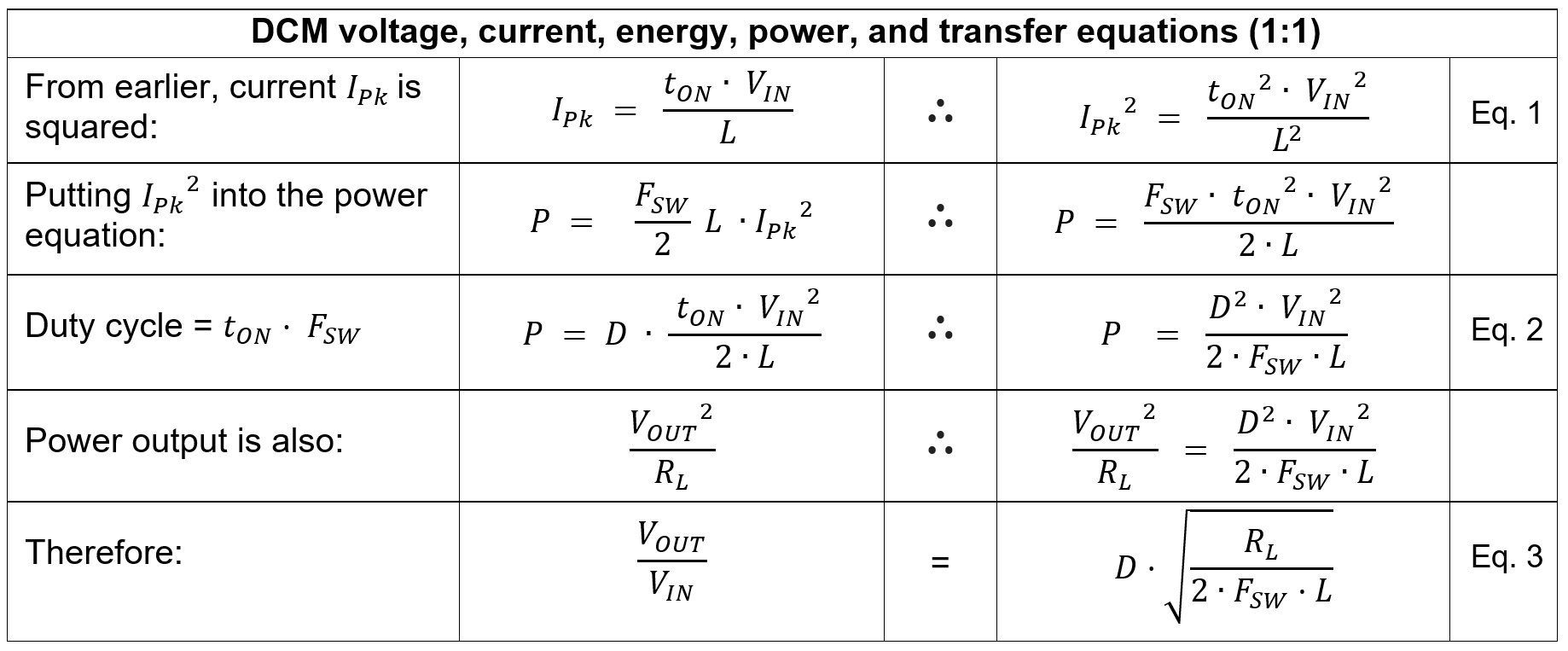
- # What DCM duty cycle is needed?
- We need to deliver a power of 25 watts to sustain 500 volts across a 10 kΩ output load. So now we reverse back from 25 watts and calculate energy transfer (W) per switching cycle.
- $$W = \dfrac{\text{25 watts}}{\text{100 kHz}} = \text{250 μJ}$$
- This means that the peak current in the inductor is: -
- $$I_{PK} = \sqrt{\dfrac{2\cdot W}{L}} = \text{ 0.7071 amps}$$
- And, given that we know \$V_{IN}\$ and \$L\$, we can calculate \$t_1\$ by: -
- $$t_1 = \dfrac{L\cdot I_{PK}}{V_{IN}} = \text{5.657 μs}$$
- $$\color{red}{\boxed\{\large\text{This of course is a duty cycle of 0.5657}}}$$
- Here's a simulation tool that demonstrates the current waveforms for a 1:1 transformer: -
- 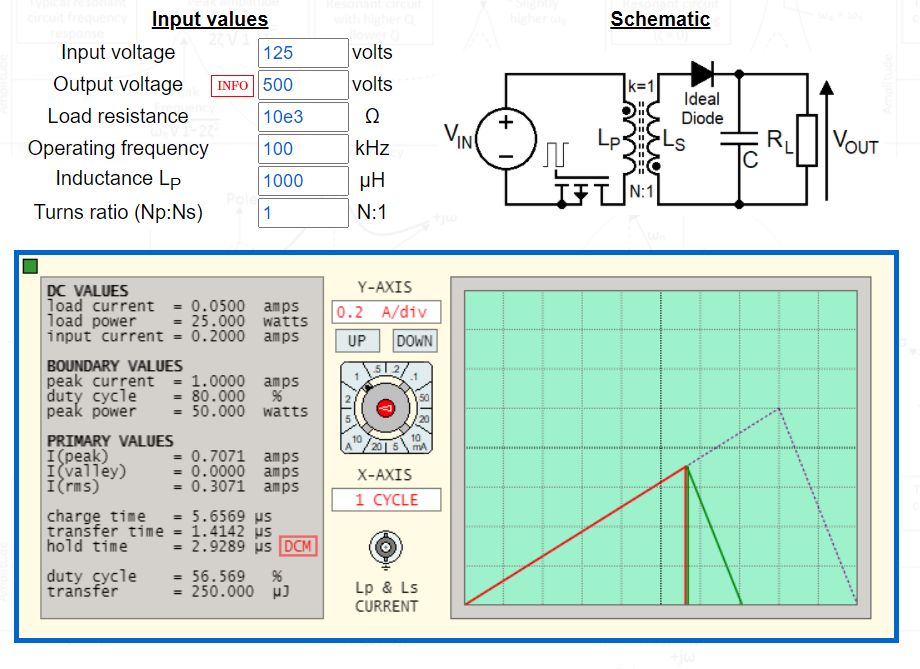
- Hopefully, once I've ironed out a couple of bugs, I'll make this tool available on-line.
- -----
- # Summary of DCM equations, 1:1 transformer
- 
- # Summary of CCM equations, 1:1 transformer
- 
- 
- -----
- # Flyback voltage considerations
- In the example above we used a 1:1 flyback transformer to produce 500 volts DC on the secondary. The "flyback" that creates 500 volts DC on the output also gets 1:1 reflected to the primary winding and this means that when the MOSFET switch is deactivated, the DRAIN will see the input voltage (125 volts) plus the 500 volts of flyback. This means that the MOSFET will need to be rated sparingly in excess of 625 volts to avoid damage.
- **Using a step-up transformer**
- To reduce this we can use a step-up secondary winding. For example, if a 1:2 step-up transformer is used then the secondary "flyback" of 500 volts is only 250 volts on the primary and, this means the MOSFET can be rated greater than 375 volts on the DRAIN. If a 1:4 transformer is used, the primary "flyback" is 125 volts and a MOSFET with a rating greater than 250 volts can be chosen: -
- 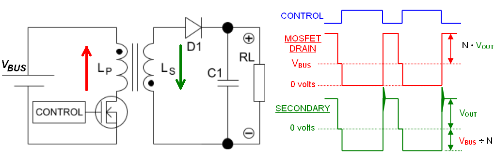
- Note the "N" factor in the above relationships for \$V_{SECONDARY}\$ and \$V_{PRIMARY}\$.
- **Leakage Inductance considerations**
- There will always be energy stored in the primary that cannot be transferred to the secondary because the two coils will never be 100% coupled. The outcome of this is that when the MOSFET turns off, in addition to the fly-back voltage raising the drain higher than \$V_{IN}\$ there will be an extra spike due to leakage inductance. This can be dealt with using a diode-capacitor-resistor clamp or a zener clamp: -
- 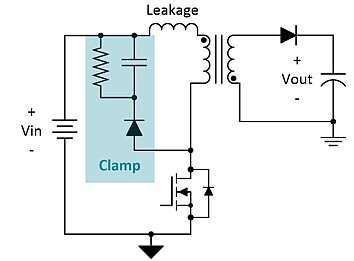
- Above picture from [here](https://www.edn.com/power-tips-91-how-to-improve-flyback-efficiency-with-a-nondissipative-clamp/).
- 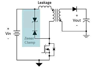
- Note that the zener diode has to allow the normal flyback voltage to occur hence its voltage rating has to be greater than the natural flyback voltage seen on the primary winding.
- -----
- -----
- # Micro-cap 12 simulation 1:1 transformer
- 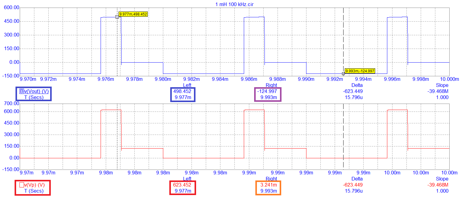
- - \$V_{IN}\$ is 125 volts
- - D is set to 0.5657
- - The peak \$V_{OUT}\$ is 498.45 volts (target 500 volts)
- - The reflected primary voltage is 623.45 volts (498.45 + 125 volts)
- # Equivalent Circuit, 1:1 transformer
- Start by simplifying the circuit and change the transformer to a single inductor. This simplification ignores the benefits of isolation but, flyback converter theory is about transferring energy and not fundamentally about isolation: -
- 
- We also don't need to worry about the output polarity being inverted because, when a transformer is used in the real circuit, isolation and correct DC polarity are delivered
- # The Operating mode, 1:1 transformer
- The circuit operates in either of two modes but, the voltage transfer equation is different for each mode. Therefore, you need to establish the operating mode before you can calculate duty cycle. The operating modes are: -
- - **DCM** (discontinuous conduction mode) - inductor current will fall to zero amps. Accommodates light to medium load currents. Duty cycle lower than **CCM**.
- - **CCM** (continuous conduction mode) - inductor current remains above zero amps. Accommodates medium to heavier load currents. Duty cycle higher than **DCM**.
- -----
- **DCM** has three distinct phases per switching cycle; charge (red), transfer (green) and hold. The length of the hold-phase accommodates load current variations: -
- 
- -----
- **CCM** has just two phases; charge (red) and transfer (green). Load current changes are accommodated by the whole of the inductor current waveform rising or falling: -
- 
- **CCM and DCM summary**
- Only one mode will deliver 500 volts to the 10 kΩ load with \$V_{IN}\$, \$L\$ and \$F_{SW}\$ as specified.
- - Lighter loads are usually serviced in **DCM**
- - Heavier loads are usually serviced in **CCM**
- - **CCM** is a natural outcome when **DCM** can't service the heavier load
- - **DCM** is a natural outcome when **CCM** can't service the lighter load
- The next step is to decide which operating mode fulfills the requirements of the proposed design. To do this we consider the boundary condition.
- -----
- # Boundary condition, 1:1 transformer
- This is where **DCM** meets **CCM**; the inductor has delivered all it's energy to the output and the switching cycle restarts immediately. We then need to ask this hypothetical question: -
- $$\color{red}{\boxed\{\large\text{Is the boundary power transfer more than required by the load?}}}$$
- If the answer is yes, then we will operate in **DCM**. If the answer is no we will operate in **CCM**.
- **Boundary Power Transfer Analysis**
- 
- We need to find the input output relationship and duty cycle in the boundary condition. Simple analysis tells us: -
- $$\text{boundary condition }\Bigg\rvert\dfrac{V_O}{V_{IN}} = \dfrac{D}{1-D}\text{ and } D = \dfrac{V_O}{V_{IN}+V_O}\Bigg\rvert\text{ boundary condition}$$
- Calculate D using the values in the question: -
- $$D = \dfrac{V_O}{V_{IN}+V_O} = \dfrac{500}{125+500} = 0.8000$$
- This also delivers \$t_1\$ (time taken to charge the inductor): -
- $$t_1 = \dfrac{D}{F_{SW}} = \dfrac{0.8}{\text{100 kHz}} = \text{8 μs}$$
- # Calculating \$I_{PK}\$ in the boundary condition
- Using Faraday's equation for an inductor we know: -
- $$\boxed{V = L\cdot\dfrac{di}{dt}}$$
- - \$V = V_{IN}\$ = 125 volts
- - \$di = I_{PK}\$ (the peak current at the end of phase 1)
- - \$dt = t_1\$ = 8 μs
- - \$L\ =$ inductance (1 mH in this example)
- Hence:
- $$V_{IN} = L\cdot\dfrac{I_{PK}}{t_1}\therefore I_{PK} = \dfrac{t_1\cdot V_{IN}}{L} = \text{ 1.00 amps}$$
- # The stored energy (W) in boundary condition
- The inductor's stored energy (W) is found using this well-known formula: -
- $$\boxed{W = \dfrac{1}{2}\cdot L\cdot I_{PK}^2}$$
- If we plug the numbers in for current and inductance we get an energy figure of 500 μJ.
- # The power transfer in the boundary condition
- Inductor stored energy of 500 μJ is transferred to the load 100,000 times per second (\$F_{SW}\$).
- $$\color{red}{\boxed\{\large\text{This is an equivalent continuous power transfer of 50 watts}}}$$
- # How much power is transferred to the actual load?
- Unlike the boost converter, all the load power comes through charging the magnetics hence the load requires 500\$^2\$/10 kΩ = 25 watts. This is significantly less than the power that _could_ be transferred in the boundary condition therefore: -
- $$\color{red}{\boxed\{\large\text{The flyback converter will operate in DCM}}}$$
- # What DCM duty cycle is needed?
- We need to deliver a power of 25 watts to sustain 500 volts across a 10 kΩ output load. So now we reverse back from 25 watts and calculate energy transfer (W) per switching cycle.
- $$W = \dfrac{\text{25 watts}}{\text{100 kHz}} = \text{250 μJ}$$
- This means that the peak current in the inductor is: -
- $$I_{PK} = \sqrt{\dfrac{2\cdot W}{L}} = \text{ 0.7071 amps}$$
- And, given that we know \$V_{IN}\$ and \$L\$, we can calculate \$t_1\$ by: -
- $$t_1 = \dfrac{L\cdot I_{PK}}{V_{IN}} = \text{5.657 μs}$$
- $$\color{red}{\boxed\{\large\text{This of course is a duty cycle of 0.5657}}}$$
- Here's a simulation tool that demonstrates the current waveforms for a 1:1 transformer: -
- 
- Hopefully, once I've ironed out a couple of bugs, I'll make this tool available on-line.
- -----
- # Summary of DCM equations, 1:1 transformer
- 
- # Summary of CCM equations, 1:1 transformer
- 
- 
- -----
- # Flyback voltage considerations
- In the example above we used a 1:1 flyback transformer to produce 500 volts DC on the secondary. The "flyback" that creates 500 volts DC on the output also gets 1:1 reflected to the primary winding and this means that when the MOSFET switch is deactivated, the DRAIN will see the input voltage (125 volts) plus the 500 volts of flyback. This means that the MOSFET will need to be rated sparingly in excess of 625 volts to avoid damage.
- **Using a step-up transformer**
- To reduce this we can use a step-up secondary winding. For example, if a 1:2 step-up transformer is used then the secondary "flyback" of 500 volts is only 250 volts on the primary and, this means the MOSFET can be rated greater than 375 volts on the DRAIN. If a 1:4 transformer is used, the primary "flyback" is 125 volts and a MOSFET with a rating greater than 250 volts can be chosen: -
- 
- Note the "N" factor in the above relationships for \$V_{SECONDARY}\$ and \$V_{PRIMARY}\$.
- **Leakage Inductance considerations**
- There will always be energy stored in the primary that cannot be transferred to the secondary because the two coils will never be 100% coupled. The outcome of this is that when the MOSFET turns off, in addition to the fly-back voltage raising the drain higher than \$V_{IN}\$ there will be an extra spike due to leakage inductance. This can be dealt with using a diode-capacitor-resistor clamp or a zener clamp: -
- 
- Above picture from [here](https://www.edn.com/power-tips-91-how-to-improve-flyback-efficiency-with-a-nondissipative-clamp/).
- 
- Note that the zener diode has to allow the normal flyback voltage to occur hence its voltage rating has to be greater than the natural flyback voltage seen on the primary winding.
- -----
- -----
- # Micro-cap 12 simulation 1:1 transformer
- 
- - \$V_{IN}\$ is 125 volts
- - D is set to 0.5657
- - The peak \$V_{OUT}\$ is 498.45 volts (target 500 volts)
- - The reflected primary voltage is 623.45 volts (498.45 + 125 volts)
#19: Post edited
by
Andy aka
·
2022-01-05T17:06:50Z (over 3 years ago)
- # Equivalent Circuit, 1:1 transformer
- Start by simplifying the circuit and change the transformer to a single inductor. This simplification ignores the benefits of isolation but, flyback converter theory is about transferring energy and not fundamentally about isolation: -
- 
- We also don't need to worry about the output polarity being inverted because, when a transformer is used in the real circuit, isolation and correct DC polarity are delivered
- # The Operating mode, 1:1 transformer
- The circuit operates in either of two modes but, the voltage transfer equation is different for each mode. Therefore, you need to establish the operating mode before you can calculate duty cycle. The operating modes are: -
- - **DCM** (discontinuous conduction mode) - inductor current will fall to zero amps. Accommodates light to medium load currents. Duty cycle lower than **CCM**.
- - **CCM** (continuous conduction mode) - inductor current remains above zero amps. Accommodates medium to heavier load currents. Duty cycle higher than **DCM**.
- -----
- **DCM** has three distinct phases per switching cycle; charge (red), transfer (green) and hold. The length of the hold-phase accommodates load current variations: -
- 
- -----
- **CCM** has just two phases; charge (red) and transfer (green). Load current changes are accommodated by the whole of the inductor current waveform rising or falling: -
- 
- **CCM and DCM summary**
- Only one mode will deliver 500 volts to the 10 kΩ load with \$V_{IN}\$, \$L\$ and \$F_{SW}\$ as specified.
- - Lighter loads are usually serviced in **DCM**
- - Heavier loads are usually serviced in **CCM**
- - **CCM** is a natural outcome when **DCM** can't service the heavier load
- - **DCM** is a natural outcome when **CCM** can't service the lighter load
- The next step is to decide which operating mode fulfills the requirements of the proposed design. To do this we consider the boundary condition.
- -----
- # Boundary condition, 1:1 transformer
- This is where **DCM** meets **CCM**; the inductor has delivered all it's energy to the output and the switching cycle restarts immediately. We then need to ask this hypothetical question: -
- $$\color{red}{\boxed\{\large\text{At the boundary, is the load power sufficient to sustain \$V_{OUT}\$}}}$$
- If the answer is yes, then we will operate in **DCM**. If the answer is no we will operate in **CCM**.
- **Boundary Power Transfer Analysis**
- 
- We need to find the input output relationship and duty cycle in the boundary condition. Simple analysis tells us: -
- $$\text{boundary condition }\Bigg\rvert\dfrac{V_O}{V_{IN}} = \dfrac{D}{1-D}\text{ and } D = \dfrac{V_O}{V_{IN}+V_O}\Bigg\rvert\text{ boundary condition}$$
- Calculate D using the values in the question: -
- $$D = \dfrac{V_O}{V_{IN}+V_O} = \dfrac{500}{125+500} = 0.8000$$
- This also delivers \$t_1\$ (time taken to charge the inductor): -
- $$t_1 = \dfrac{D}{F_{SW}} = \dfrac{0.8}{\text{100 kHz}} = \text{8 μs}$$
- # Calculating \$I_{PK}\$ in the boundary condition
- Using Faraday's equation for an inductor we know: -
- $$\boxed{V = L\cdot\dfrac{di}{dt}}$$
- - \$V = V_{IN}\$ = 125 volts
- - \$di = I_{PK}\$ (the peak current at the end of phase 1)
- - \$dt = t_1\$ = 8 μs
- - \$L\ =$ inductance (1 mH in this example)
- Hence:
- $$V_{IN} = L\cdot\dfrac{I_{PK}}{t_1}\therefore I_{PK} = \dfrac{t_1\cdot V_{IN}}{L} = \text{ 1.00 amps}$$
- # The stored energy (W) in boundary condition
- The inductor's stored energy (W) is found using this well-known formula: -
- $$\boxed{W = \dfrac{1}{2}\cdot L\cdot I_{PK}^2}$$
- If we plug the numbers in for current and inductance we get an energy figure of 500 μJ.
- # The power transfer in the boundary condition
- Inductor stored energy of 500 μJ is transferred to the load 100,000 times per second (\$F_{SW}\$).
- $$\color{red}{\boxed\{\large\text{This is an equivalent continuous power transfer of 50 watts}}}$$
- # How much power is transferred to the actual load?
- Unlike the boost converter, all the load power comes through charging the magnetics hence the load requires 500\$^2\$/10 kΩ = 25 watts. This is significantly less than the power that _could_ be transferred in the boundary condition therefore: -
- $$\color{red}{\boxed\{\large\text{The flyback converter will operate in DCM}}}$$
- # What DCM duty cycle is needed?
- We need to deliver a power of 25 watts to sustain 500 volts across a 10 kΩ output load. So now we reverse back from 25 watts and calculate energy transfer (W) per switching cycle.
- $$W = \dfrac{\text{25 watts}}{\text{100 kHz}} = \text{250 μJ}$$
- This means that the peak current in the inductor is: -
- $$I_{PK} = \sqrt{\dfrac{2\cdot W}{L}} = \text{ 0.7071 amps}$$
- And, given that we know \$V_{IN}\$ and \$L\$, we can calculate \$t_1\$ by: -
- $$t_1 = \dfrac{L\cdot I_{PK}}{V_{IN}} = \text{5.657 μs}$$
- $$\color{red}{\boxed\{\large\text{This of course is a duty cycle of 0.5657}}}$$
- -----
- # Summary of DCM equations, 1:1 transformer
- 
- # Summary of CCM equations, 1:1 transformer
- 
- 
- -----
- # Flyback voltage considerations
- In the example above we used a 1:1 flyback transformer to produce 500 volts DC on the secondary. The "flyback" that creates 500 volts DC on the output also gets 1:1 reflected to the primary winding and this means that when the MOSFET switch is deactivated, the DRAIN will see the input voltage (125 volts) plus the 500 volts of flyback. This means that the MOSFET will need to be rated sparingly in excess of 625 volts to avoid damage.
- **Using a step-up transformer**
- To reduce this we can use a step-up secondary winding. For example, if a 1:2 step-up transformer is used then the secondary "flyback" of 500 volts is only 250 volts on the primary and, this means the MOSFET can be rated greater than 375 volts on the DRAIN. If a 1:4 transformer is used, the primary "flyback" is 125 volts and a MOSFET with a rating greater than 250 volts can be chosen: -
- 
- Note the "N" factor in the above relationships for \$V_{SECONDARY}\$ and \$V_{PRIMARY}\$.
- **Leakage Inductance considerations**
- There will always be energy stored in the primary that cannot be transferred to the secondary because the two coils will never be 100% coupled. The outcome of this is that when the MOSFET turns off, in addition to the fly-back voltage raising the drain higher than \$V_{IN}\$ there will be an extra spike due to leakage inductance. This can be dealt with using a diode-capacitor-resistor clamp or a zener clamp: -
- 
- Above picture from [here](https://www.edn.com/power-tips-91-how-to-improve-flyback-efficiency-with-a-nondissipative-clamp/).
- 
- Note that the zener diode has to allow the normal flyback voltage to occur hence its voltage rating has to be greater than the natural flyback voltage seen on the primary winding.
- -----
- -----
- # Micro-cap 12 simulation 1:1 transformer
- 
- - \$V_{IN}\$ is 125 volts
- - D is set to 0.5657
- - The peak \$V_{OUT}\$ is 498.45 volts (target 500 volts)
- - The reflected primary voltage is 623.45 volts (498.45 + 125 volts)
- # Equivalent Circuit, 1:1 transformer
- Start by simplifying the circuit and change the transformer to a single inductor. This simplification ignores the benefits of isolation but, flyback converter theory is about transferring energy and not fundamentally about isolation: -
- 
- We also don't need to worry about the output polarity being inverted because, when a transformer is used in the real circuit, isolation and correct DC polarity are delivered
- # The Operating mode, 1:1 transformer
- The circuit operates in either of two modes but, the voltage transfer equation is different for each mode. Therefore, you need to establish the operating mode before you can calculate duty cycle. The operating modes are: -
- - **DCM** (discontinuous conduction mode) - inductor current will fall to zero amps. Accommodates light to medium load currents. Duty cycle lower than **CCM**.
- - **CCM** (continuous conduction mode) - inductor current remains above zero amps. Accommodates medium to heavier load currents. Duty cycle higher than **DCM**.
- -----
- **DCM** has three distinct phases per switching cycle; charge (red), transfer (green) and hold. The length of the hold-phase accommodates load current variations: -
- 
- -----
- **CCM** has just two phases; charge (red) and transfer (green). Load current changes are accommodated by the whole of the inductor current waveform rising or falling: -
- 
- **CCM and DCM summary**
- Only one mode will deliver 500 volts to the 10 kΩ load with \$V_{IN}\$, \$L\$ and \$F_{SW}\$ as specified.
- - Lighter loads are usually serviced in **DCM**
- - Heavier loads are usually serviced in **CCM**
- - **CCM** is a natural outcome when **DCM** can't service the heavier load
- - **DCM** is a natural outcome when **CCM** can't service the lighter load
- The next step is to decide which operating mode fulfills the requirements of the proposed design. To do this we consider the boundary condition.
- -----
- # Boundary condition, 1:1 transformer
- This is where **DCM** meets **CCM**; the inductor has delivered all it's energy to the output and the switching cycle restarts immediately. We then need to ask this hypothetical question: -
- $$\color{red}{\boxed\{\large\text{At the boundary, is the load power sufficient to sustain \$V_{OUT}\$}}}$$
- If the answer is yes, then we will operate in **DCM**. If the answer is no we will operate in **CCM**.
- **Boundary Power Transfer Analysis**
- 
- We need to find the input output relationship and duty cycle in the boundary condition. Simple analysis tells us: -
- $$\text{boundary condition }\Bigg\rvert\dfrac{V_O}{V_{IN}} = \dfrac{D}{1-D}\text{ and } D = \dfrac{V_O}{V_{IN}+V_O}\Bigg\rvert\text{ boundary condition}$$
- Calculate D using the values in the question: -
- $$D = \dfrac{V_O}{V_{IN}+V_O} = \dfrac{500}{125+500} = 0.8000$$
- This also delivers \$t_1\$ (time taken to charge the inductor): -
- $$t_1 = \dfrac{D}{F_{SW}} = \dfrac{0.8}{\text{100 kHz}} = \text{8 μs}$$
- # Calculating \$I_{PK}\$ in the boundary condition
- Using Faraday's equation for an inductor we know: -
- $$\boxed{V = L\cdot\dfrac{di}{dt}}$$
- - \$V = V_{IN}\$ = 125 volts
- - \$di = I_{PK}\$ (the peak current at the end of phase 1)
- - \$dt = t_1\$ = 8 μs
- - \$L\ =$ inductance (1 mH in this example)
- Hence:
- $$V_{IN} = L\cdot\dfrac{I_{PK}}{t_1}\therefore I_{PK} = \dfrac{t_1\cdot V_{IN}}{L} = \text{ 1.00 amps}$$
- # The stored energy (W) in boundary condition
- The inductor's stored energy (W) is found using this well-known formula: -
- $$\boxed{W = \dfrac{1}{2}\cdot L\cdot I_{PK}^2}$$
- If we plug the numbers in for current and inductance we get an energy figure of 500 μJ.
- # The power transfer in the boundary condition
- Inductor stored energy of 500 μJ is transferred to the load 100,000 times per second (\$F_{SW}\$).
- $$\color{red}{\boxed\{\large\text{This is an equivalent continuous power transfer of 50 watts}}}$$
- # How much power is transferred to the actual load?
- Unlike the boost converter, all the load power comes through charging the magnetics hence the load requires 500\$^2\$/10 kΩ = 25 watts. This is significantly less than the power that _could_ be transferred in the boundary condition therefore: -
- $$\color{red}{\boxed\{\large\text{The flyback converter will operate in DCM}}}$$
- # What DCM duty cycle is needed?
- We need to deliver a power of 25 watts to sustain 500 volts across a 10 kΩ output load. So now we reverse back from 25 watts and calculate energy transfer (W) per switching cycle.
- $$W = \dfrac{\text{25 watts}}{\text{100 kHz}} = \text{250 μJ}$$
- This means that the peak current in the inductor is: -
- $$I_{PK} = \sqrt{\dfrac{2\cdot W}{L}} = \text{ 0.7071 amps}$$
- And, given that we know \$V_{IN}\$ and \$L\$, we can calculate \$t_1\$ by: -
- $$t_1 = \dfrac{L\cdot I_{PK}}{V_{IN}} = \text{5.657 μs}$$
- $$\color{red}{\boxed\{\large\text{This of course is a duty cycle of 0.5657}}}$$
- Here's a simulation tool that demonstrates the current waveforms for a 1:1 transformer: -
- 
- Hopefully, once I've ironed out a couple of bugs, I'll make this tool available on-line.
- -----
- # Summary of DCM equations, 1:1 transformer
- 
- # Summary of CCM equations, 1:1 transformer
- 
- 
- -----
- # Flyback voltage considerations
- In the example above we used a 1:1 flyback transformer to produce 500 volts DC on the secondary. The "flyback" that creates 500 volts DC on the output also gets 1:1 reflected to the primary winding and this means that when the MOSFET switch is deactivated, the DRAIN will see the input voltage (125 volts) plus the 500 volts of flyback. This means that the MOSFET will need to be rated sparingly in excess of 625 volts to avoid damage.
- **Using a step-up transformer**
- To reduce this we can use a step-up secondary winding. For example, if a 1:2 step-up transformer is used then the secondary "flyback" of 500 volts is only 250 volts on the primary and, this means the MOSFET can be rated greater than 375 volts on the DRAIN. If a 1:4 transformer is used, the primary "flyback" is 125 volts and a MOSFET with a rating greater than 250 volts can be chosen: -
- 
- Note the "N" factor in the above relationships for \$V_{SECONDARY}\$ and \$V_{PRIMARY}\$.
- **Leakage Inductance considerations**
- There will always be energy stored in the primary that cannot be transferred to the secondary because the two coils will never be 100% coupled. The outcome of this is that when the MOSFET turns off, in addition to the fly-back voltage raising the drain higher than \$V_{IN}\$ there will be an extra spike due to leakage inductance. This can be dealt with using a diode-capacitor-resistor clamp or a zener clamp: -
- 
- Above picture from [here](https://www.edn.com/power-tips-91-how-to-improve-flyback-efficiency-with-a-nondissipative-clamp/).
- 
- Note that the zener diode has to allow the normal flyback voltage to occur hence its voltage rating has to be greater than the natural flyback voltage seen on the primary winding.
- -----
- -----
- # Micro-cap 12 simulation 1:1 transformer
- 
- - \$V_{IN}\$ is 125 volts
- - D is set to 0.5657
- - The peak \$V_{OUT}\$ is 498.45 volts (target 500 volts)
- - The reflected primary voltage is 623.45 volts (498.45 + 125 volts)
#18: Post edited
by
Andy aka
·
2022-01-03T15:40:20Z (over 3 years ago)
- # Equivalent Circuit, 1:1 transformer
- Start by simplifying the circuit and change the transformer to a single inductor. This simplification ignores the benefits of isolation but, flyback converter theory is about transferring energy and not fundamentally about isolation: -
- 
- We also don't need to worry about the output polarity being inverted because, when a transformer is used in the real circuit, isolation and correct DC polarity are delivered
- # The Operating mode, 1:1 transformer
- The circuit operates in either of two modes but, the voltage transfer equation is different for each mode. Therefore, you need to establish the operating mode before you can calculate duty cycle. The operating modes are: -
- - **DCM** (discontinuous conduction mode) - inductor current will fall to zero amps. Accommodates light to medium load currents. Duty cycle lower than **CCM**.
- - **CCM** (continuous conduction mode) - inductor current remains above zero amps. Accommodates medium to heavier load currents. Duty cycle higher than **DCM**.
- -----
- **DCM** has three distinct phases per switching cycle; charge (red), transfer (green) and hold. The length of the hold-phase accommodates load current variations: -
- 
- -----
- **CCM** has just two phases; charge (red) and transfer (green). Load current changes are accommodated by the whole of the inductor current waveform rising or falling: -
- 
- **CCM and DCM summary**
- Only one mode will deliver 500 volts to the 10 kΩ load with \$V_{IN}\$, \$L\$ and \$F_{SW}\$ as specified.
- - Lighter loads are usually serviced in **DCM**
- - Heavier loads are usually serviced in **CCM**
- - **CCM** is a natural outcome when **DCM** can't service the heavier load
- - **DCM** is a natural outcome when **CCM** can't service the lighter load
- The next step is to decide which operating mode fulfills the requirements of the proposed design. To do this we consider the boundary condition.
- -----
- # Boundary condition, 1:1 transformer
- This is where **DCM** meets **CCM**; the inductor has delivered all it's energy to the output and the switching cycle restarts immediately. We then need to ask this hypothetical question: -
- $$\color{red}{\boxed\{\large\text{At the boundary, is the load power sufficient to sustain \$V_{OUT}\$}}}$$
- If the answer is yes, then we will operate in **DCM**. If the answer is no we will operate in **CCM**.
- **Boundary Power Transfer Analysis**
- 
- We need to find the input output relationship and duty cycle in the boundary condition. Simple analysis tells us: -
- $$\text{boundary condition }\Bigg\rvert\dfrac{V_O}{V_{IN}} = \dfrac{D}{1-D}\text{ and } D = \dfrac{V_O}{V_{IN}+V_O}\Bigg\rvert\text{ boundary condition}$$
- Calculate D using the values in the question: -
- $$D = \dfrac{V_O}{V_{IN}+V_O} = \dfrac{500}{125+500} = 0.8000$$
- This also delivers \$t_1\$ (time taken to charge the inductor): -
- $$t_1 = \dfrac{D}{F_{SW}} = \dfrac{0.8}{\text{100 kHz}} = \text{8 μs}$$
- # Calculating \$I_{PK}\$ in the boundary condition
- Using Faraday's equation for an inductor we know: -
- $$\boxed{V = L\cdot\dfrac{di}{dt}}$$
- - \$V = V_{IN}\$ = 125 volts
- - \$di = I_{PK}\$ (the peak current at the end of phase 1)
- - \$dt = t_1\$ = 8 μs
- - \$L\ =$ inductance (1 mH in this example)
- Hence:
- $$V_{IN} = L\cdot\dfrac{I_{PK}}{t_1}\therefore I_{PK} = \dfrac{t_1\cdot V_{IN}}{L} = \text{ 1.00 amps}$$
- # The stored energy (W) in boundary condition
- The inductor's stored energy (W) is found using this well-known formula: -
- $$\boxed{W = \dfrac{1}{2}\cdot L\cdot I_{PK}^2}$$
- If we plug the numbers in for current and inductance we get an energy figure of 500 μJ.
- # The power transfer in the boundary condition
- Inductor stored energy of 500 μJ is transferred to the load 100,000 times per second (\$F_{SW}\$).
- $$\color{red}{\boxed\{\large\text{This is an equivalent continuous power transfer of 50 watts}}}$$
- # How much power is transferred to the actual load?
- Unlike the boost converter, all the load power comes through charging the magnetics hence the load requires 500\$^2\$/10 kΩ = 25 watts. This is significantly less than the power that _could_ be transferred in the boundary condition therefore: -
- $$\color{red}{\boxed\{\large\text{The flyback converter will operate in DCM}}}$$
- # What DCM duty cycle is needed?
- We need to deliver a power of 25 watts to sustain 500 volts across a 10 kΩ output load. So now we reverse back from 25 watts and calculate energy transfer (W) per switching cycle.
- $$W = \dfrac{\text{25 watts}}{\text{100 kHz}} = \text{250 μJ}$$
- This means that the peak current in the inductor is: -
- $$I_{PK} = \sqrt{\dfrac{2\cdot W}{L}} = \text{ 0.7071 amps}$$
- And, given that we know \$V_{IN}\$ and \$L\$, we can calculate \$t_1\$ by: -
- $$t_1 = \dfrac{L\cdot I_{PK}}{V_{IN}} = \text{5.657 μs}$$
- $$\color{red}{\boxed\{\large\text{This of course is a duty cycle of 0.5657}}}$$
- -----
- # Summary of DCM equations, 1:1 transformer
- 
- # Summary of CCM equations, 1:1 transformer
- 
- 
- -----
- # Flyback voltage considerations
- In the example above we used a 1:1 flyback transformer to produce 500 volts DC on the secondary. The "flyback" that creates 500 volts DC on the output also gets 1:1 reflected to the primary winding and this means that when the MOSFET switch is deactivated, the DRAIN will see the input voltage (125 volts) plus the 500 volts of flyback. This means that the MOSFET will need to be rated sparingly in excess of 625 volts to avoid damage.
- **Using a step-up transformer**
- To reduce this we can use a step-up secondary winding. For example, if a 1:2 step-up transformer is used then the secondary "flyback" of 500 volts is only 250 volts on the primary and, this means the MOSFET can be rated greater than 375 volts on the DRAIN. If a 1:4 transformer is used, the primary "flyback" is 125 volts and a MOSFET with a rating greater than 250 volts can be chosen: -
- 
- Note the "N" factor in the above relationships for \$V_{SECONDARY}\$ and \$V_{PRIMARY}\$.
- **Leakage Inductance considerations**
- There will always be energy stored in the primary that cannot be transferred to the secondary because the two coils will never be 100% coupled. The outcome of this is that when the MOSFET turns off, in addition to the fly-back voltage raising the drain higher than \$V_{IN}\$ there will be an extra spike due to leakage inductance. This can be dealt with using a diode-capacitor-resistor clamp or a zener clamp: -
- 
- Above picture from [here](https://www.edn.com/power-tips-91-how-to-improve-flyback-efficiency-with-a-nondissipative-clamp/).
- 
- Note that the zener diode has to allow the normal flyback voltage to occur hence its voltage rating has to be greater than the natural flyback voltage seen on the primary winding.
- -----
# Equivalent circuit, N:1 step-down transformer# Summary of equations, N:1 step-down transformer- -----
- # Micro-cap 12 simulation 1:1 transformer
- 
- - \$V_{IN}\$ is 125 volts
- - D is set to 0.5657
- - The peak \$V_{OUT}\$ is 498.45 volts (target 500 volts)
- - The reflected primary voltage is 623.45 volts (498.45 + 125 volts)
- # Equivalent Circuit, 1:1 transformer
- Start by simplifying the circuit and change the transformer to a single inductor. This simplification ignores the benefits of isolation but, flyback converter theory is about transferring energy and not fundamentally about isolation: -
- 
- We also don't need to worry about the output polarity being inverted because, when a transformer is used in the real circuit, isolation and correct DC polarity are delivered
- # The Operating mode, 1:1 transformer
- The circuit operates in either of two modes but, the voltage transfer equation is different for each mode. Therefore, you need to establish the operating mode before you can calculate duty cycle. The operating modes are: -
- - **DCM** (discontinuous conduction mode) - inductor current will fall to zero amps. Accommodates light to medium load currents. Duty cycle lower than **CCM**.
- - **CCM** (continuous conduction mode) - inductor current remains above zero amps. Accommodates medium to heavier load currents. Duty cycle higher than **DCM**.
- -----
- **DCM** has three distinct phases per switching cycle; charge (red), transfer (green) and hold. The length of the hold-phase accommodates load current variations: -
- 
- -----
- **CCM** has just two phases; charge (red) and transfer (green). Load current changes are accommodated by the whole of the inductor current waveform rising or falling: -
- 
- **CCM and DCM summary**
- Only one mode will deliver 500 volts to the 10 kΩ load with \$V_{IN}\$, \$L\$ and \$F_{SW}\$ as specified.
- - Lighter loads are usually serviced in **DCM**
- - Heavier loads are usually serviced in **CCM**
- - **CCM** is a natural outcome when **DCM** can't service the heavier load
- - **DCM** is a natural outcome when **CCM** can't service the lighter load
- The next step is to decide which operating mode fulfills the requirements of the proposed design. To do this we consider the boundary condition.
- -----
- # Boundary condition, 1:1 transformer
- This is where **DCM** meets **CCM**; the inductor has delivered all it's energy to the output and the switching cycle restarts immediately. We then need to ask this hypothetical question: -
- $$\color{red}{\boxed\{\large\text{At the boundary, is the load power sufficient to sustain \$V_{OUT}\$}}}$$
- If the answer is yes, then we will operate in **DCM**. If the answer is no we will operate in **CCM**.
- **Boundary Power Transfer Analysis**
- 
- We need to find the input output relationship and duty cycle in the boundary condition. Simple analysis tells us: -
- $$\text{boundary condition }\Bigg\rvert\dfrac{V_O}{V_{IN}} = \dfrac{D}{1-D}\text{ and } D = \dfrac{V_O}{V_{IN}+V_O}\Bigg\rvert\text{ boundary condition}$$
- Calculate D using the values in the question: -
- $$D = \dfrac{V_O}{V_{IN}+V_O} = \dfrac{500}{125+500} = 0.8000$$
- This also delivers \$t_1\$ (time taken to charge the inductor): -
- $$t_1 = \dfrac{D}{F_{SW}} = \dfrac{0.8}{\text{100 kHz}} = \text{8 μs}$$
- # Calculating \$I_{PK}\$ in the boundary condition
- Using Faraday's equation for an inductor we know: -
- $$\boxed{V = L\cdot\dfrac{di}{dt}}$$
- - \$V = V_{IN}\$ = 125 volts
- - \$di = I_{PK}\$ (the peak current at the end of phase 1)
- - \$dt = t_1\$ = 8 μs
- - \$L\ =$ inductance (1 mH in this example)
- Hence:
- $$V_{IN} = L\cdot\dfrac{I_{PK}}{t_1}\therefore I_{PK} = \dfrac{t_1\cdot V_{IN}}{L} = \text{ 1.00 amps}$$
- # The stored energy (W) in boundary condition
- The inductor's stored energy (W) is found using this well-known formula: -
- $$\boxed{W = \dfrac{1}{2}\cdot L\cdot I_{PK}^2}$$
- If we plug the numbers in for current and inductance we get an energy figure of 500 μJ.
- # The power transfer in the boundary condition
- Inductor stored energy of 500 μJ is transferred to the load 100,000 times per second (\$F_{SW}\$).
- $$\color{red}{\boxed\{\large\text{This is an equivalent continuous power transfer of 50 watts}}}$$
- # How much power is transferred to the actual load?
- Unlike the boost converter, all the load power comes through charging the magnetics hence the load requires 500\$^2\$/10 kΩ = 25 watts. This is significantly less than the power that _could_ be transferred in the boundary condition therefore: -
- $$\color{red}{\boxed\{\large\text{The flyback converter will operate in DCM}}}$$
- # What DCM duty cycle is needed?
- We need to deliver a power of 25 watts to sustain 500 volts across a 10 kΩ output load. So now we reverse back from 25 watts and calculate energy transfer (W) per switching cycle.
- $$W = \dfrac{\text{25 watts}}{\text{100 kHz}} = \text{250 μJ}$$
- This means that the peak current in the inductor is: -
- $$I_{PK} = \sqrt{\dfrac{2\cdot W}{L}} = \text{ 0.7071 amps}$$
- And, given that we know \$V_{IN}\$ and \$L\$, we can calculate \$t_1\$ by: -
- $$t_1 = \dfrac{L\cdot I_{PK}}{V_{IN}} = \text{5.657 μs}$$
- $$\color{red}{\boxed\{\large\text{This of course is a duty cycle of 0.5657}}}$$
- -----
- # Summary of DCM equations, 1:1 transformer
- 
- # Summary of CCM equations, 1:1 transformer
- 
- 
- -----
- # Flyback voltage considerations
- In the example above we used a 1:1 flyback transformer to produce 500 volts DC on the secondary. The "flyback" that creates 500 volts DC on the output also gets 1:1 reflected to the primary winding and this means that when the MOSFET switch is deactivated, the DRAIN will see the input voltage (125 volts) plus the 500 volts of flyback. This means that the MOSFET will need to be rated sparingly in excess of 625 volts to avoid damage.
- **Using a step-up transformer**
- To reduce this we can use a step-up secondary winding. For example, if a 1:2 step-up transformer is used then the secondary "flyback" of 500 volts is only 250 volts on the primary and, this means the MOSFET can be rated greater than 375 volts on the DRAIN. If a 1:4 transformer is used, the primary "flyback" is 125 volts and a MOSFET with a rating greater than 250 volts can be chosen: -
- 
- Note the "N" factor in the above relationships for \$V_{SECONDARY}\$ and \$V_{PRIMARY}\$.
- **Leakage Inductance considerations**
- There will always be energy stored in the primary that cannot be transferred to the secondary because the two coils will never be 100% coupled. The outcome of this is that when the MOSFET turns off, in addition to the fly-back voltage raising the drain higher than \$V_{IN}\$ there will be an extra spike due to leakage inductance. This can be dealt with using a diode-capacitor-resistor clamp or a zener clamp: -
- 
- Above picture from [here](https://www.edn.com/power-tips-91-how-to-improve-flyback-efficiency-with-a-nondissipative-clamp/).
- 
- Note that the zener diode has to allow the normal flyback voltage to occur hence its voltage rating has to be greater than the natural flyback voltage seen on the primary winding.
- -----
- -----
- # Micro-cap 12 simulation 1:1 transformer
- 
- - \$V_{IN}\$ is 125 volts
- - D is set to 0.5657
- - The peak \$V_{OUT}\$ is 498.45 volts (target 500 volts)
- - The reflected primary voltage is 623.45 volts (498.45 + 125 volts)
#17: Post edited
by
Andy aka
·
2020-07-03T08:47:12Z (almost 5 years ago)
- # Equivalent Circuit, 1:1 transformer
Start by simplifying the circuit and change the transformer to a single inductor. This simplification ignores the benefits of isolation but, flyback converter theory is all about transferring energy and not fundamentally about isolation: -- 
The equivalent circuit above has two simplifications that don't affect the basic theory: -- We don't need to consider transformer isolation because it's not part of the basic math for this type of converter- We don't need to worry about the output polarity being inverted because, when a transformer is used in the real circuit, isolation and correct DC polarity are delivered- # The Operating mode, 1:1 transformer
- The circuit operates in either of two modes but, the voltage transfer equation is different for each mode. Therefore, you need to establish the operating mode before you can calculate duty cycle. The operating modes are: -
- - **DCM** (discontinuous conduction mode) - inductor current will fall to zero amps. Accommodates light to medium load currents. Duty cycle lower than **CCM**.
- - **CCM** (continuous conduction mode) - inductor current remains above zero amps. Accommodates medium to heavier load currents. Duty cycle higher than **DCM**.
- -----
- **DCM** has three distinct phases per switching cycle; charge (red), transfer (green) and hold. The length of the hold-phase accommodates load current variations: -
- 
- -----
- **CCM** has just two phases; charge (red) and transfer (green). Load current changes are accommodated by the whole of the inductor current waveform rising or falling: -
- 
- **CCM and DCM summary**
- Only one mode will deliver 500 volts to the 10 kΩ load with \$V_{IN}\$, \$L\$ and \$F_{SW}\$ as specified.
- - Lighter loads are usually serviced in **DCM**
- - Heavier loads are usually serviced in **CCM**
- - **CCM** is a natural outcome when **DCM** can't service the heavier load
- - **DCM** is a natural outcome when **CCM** can't service the lighter load
- The next step is to decide which operating mode fulfills the requirements of the proposed design. To do this we consider the boundary condition.
- -----
- # Boundary condition, 1:1 transformer
- This is where **DCM** meets **CCM**; the inductor has delivered all it's energy to the output and the switching cycle restarts immediately. We then need to ask this hypothetical question: -
- $$\color{red}{\boxed\{\large\text{At the boundary, is the load power sufficient to sustain \$V_{OUT}\$}}}$$
- If the answer is yes, then we will operate in **DCM**. If the answer is no we will operate in **CCM**.
- **Boundary Power Transfer Analysis**
- 
- We need to find the input output relationship and duty cycle in the boundary condition. Simple analysis tells us: -
- $$\text{boundary condition }\Bigg\rvert\dfrac{V_O}{V_{IN}} = \dfrac{D}{1-D}\text{ and } D = \dfrac{V_O}{V_{IN}+V_O}\Bigg\rvert\text{ boundary condition}$$
- Calculate D using the values in the question: -
- $$D = \dfrac{V_O}{V_{IN}+V_O} = \dfrac{500}{125+500} = 0.8000$$
- This also delivers \$t_1\$ (time taken to charge the inductor): -
- $$t_1 = \dfrac{D}{F_{SW}} = \dfrac{0.8}{\text{100 kHz}} = \text{8 μs}$$
- # Calculating \$I_{PK}\$ in the boundary condition
- Using Faraday's equation for an inductor we know: -
- $$\boxed{V = L\cdot\dfrac{di}{dt}}$$
- - \$V = V_{IN}\$ = 125 volts
- - \$di = I_{PK}\$ (the peak current at the end of phase 1)
- - \$dt = t_1\$ = 8 μs
- - \$L\ =$ inductance (1 mH in this example)
- Hence:
- $$V_{IN} = L\cdot\dfrac{I_{PK}}{t_1}\therefore I_{PK} = \dfrac{t_1\cdot V_{IN}}{L} = \text{ 1.00 amps}$$
- # The stored energy (W) in boundary condition
- The inductor's stored energy (W) is found using this well-known formula: -
- $$\boxed{W = \dfrac{1}{2}\cdot L\cdot I_{PK}^2}$$
- If we plug the numbers in for current and inductance we get an energy figure of 500 μJ.
- # The power transfer in the boundary condition
- Inductor stored energy of 500 μJ is transferred to the load 100,000 times per second (\$F_{SW}\$).
- $$\color{red}{\boxed\{\large\text{This is an equivalent continuous power transfer of 50 watts}}}$$
- # How much power is transferred to the actual load?
- Unlike the boost converter, all the load power comes through charging the magnetics hence the load requires 500\$^2\$/10 kΩ = 25 watts. This is significantly less than the power that _could_ be transferred in the boundary condition therefore: -
- $$\color{red}{\boxed\{\large\text{The flyback converter will operate in DCM}}}$$
- # What DCM duty cycle is needed?
- We need to deliver a power of 25 watts to sustain 500 volts across a 10 kΩ output load. So now we reverse back from 25 watts and calculate energy transfer (W) per switching cycle.
- $$W = \dfrac{\text{25 watts}}{\text{100 kHz}} = \text{250 μJ}$$
- This means that the peak current in the inductor is: -
- $$I_{PK} = \sqrt{\dfrac{2\cdot W}{L}} = \text{ 0.7071 amps}$$
- And, given that we know \$V_{IN}\$ and \$L\$, we can calculate \$t_1\$ by: -
- $$t_1 = \dfrac{L\cdot I_{PK}}{V_{IN}} = \text{5.657 μs}$$
- $$\color{red}{\boxed\{\large\text{This of course is a duty cycle of 0.5657}}}$$
- # Summary of DCM equations, 1:1 transformer
- 
- # Summary of CCM equations, 1:1 transformer
- 
- 
- # Flyback voltage considerations
- In the example above we used a 1:1 flyback transformer to produce 500 volts DC on the secondary. The "flyback" that creates 500 volts DC on the output also gets 1:1 reflected to the primary winding and this means that when the MOSFET switch is deactivated, the DRAIN will see the input voltage (125 volts) plus the 500 volts of flyback. This means that the MOSFET will need to be rated sparingly in excess of 625 volts to avoid damage.
- **Using a step-up transformer**
- To reduce this we can use a step-up secondary winding. For example, if a 1:2 step-up transformer is used then the secondary "flyback" of 500 volts is only 250 volts on the primary and, this means the MOSFET can be rated greater than 375 volts on the DRAIN. If a 1:4 transformer is used, the primary "flyback" is 125 volts and a MOSFET with a rating greater than 250 volts can be chosen: -
- 
- Note the "N" factor in the above relationships for \$V_{SECONDARY}\$ and \$V_{PRIMARY}\$.
- **Leakage Inductance considerations**
- There will always be energy stored in the primary that cannot be transferred to the secondary because the two coils will never be 100% coupled. The outcome of this is that when the MOSFET turns off, in addition to the fly-back voltage raising the drain higher than \$V_{IN}\$ there will be an extra spike due to leakage inductance. This can be dealt with using a diode-capacitor-resistor clamp or a zener clamp: -
- 
- Above picture from [here](https://www.edn.com/power-tips-91-how-to-improve-flyback-efficiency-with-a-nondissipative-clamp/).
- 
- Note that the zener diode has to allow the normal flyback voltage to occur hence its voltage rating has to be greater than the natural flyback voltage seen on the primary winding.
- # Equivalent circuit, N:1 step-down transformer
- 
- # Summary of equations, N:1 step-down transformer
- 
- # Micro-cap 12 simulation 1:1 transformer
- 
- - \$V_{IN}\$ is 125 volts
- - D is set to 0.5657
- - The peak \$V_{OUT}\$ is 498.45 volts (target 500 volts)
- - The reflected primary voltage is 623.45 volts (498.45 + 125 volts)
- # Equivalent Circuit, 1:1 transformer
- Start by simplifying the circuit and change the transformer to a single inductor. This simplification ignores the benefits of isolation but, flyback converter theory is about transferring energy and not fundamentally about isolation: -
- 
- We also don't need to worry about the output polarity being inverted because, when a transformer is used in the real circuit, isolation and correct DC polarity are delivered
- # The Operating mode, 1:1 transformer
- The circuit operates in either of two modes but, the voltage transfer equation is different for each mode. Therefore, you need to establish the operating mode before you can calculate duty cycle. The operating modes are: -
- - **DCM** (discontinuous conduction mode) - inductor current will fall to zero amps. Accommodates light to medium load currents. Duty cycle lower than **CCM**.
- - **CCM** (continuous conduction mode) - inductor current remains above zero amps. Accommodates medium to heavier load currents. Duty cycle higher than **DCM**.
- -----
- **DCM** has three distinct phases per switching cycle; charge (red), transfer (green) and hold. The length of the hold-phase accommodates load current variations: -
- 
- -----
- **CCM** has just two phases; charge (red) and transfer (green). Load current changes are accommodated by the whole of the inductor current waveform rising or falling: -
- 
- **CCM and DCM summary**
- Only one mode will deliver 500 volts to the 10 kΩ load with \$V_{IN}\$, \$L\$ and \$F_{SW}\$ as specified.
- - Lighter loads are usually serviced in **DCM**
- - Heavier loads are usually serviced in **CCM**
- - **CCM** is a natural outcome when **DCM** can't service the heavier load
- - **DCM** is a natural outcome when **CCM** can't service the lighter load
- The next step is to decide which operating mode fulfills the requirements of the proposed design. To do this we consider the boundary condition.
- -----
- # Boundary condition, 1:1 transformer
- This is where **DCM** meets **CCM**; the inductor has delivered all it's energy to the output and the switching cycle restarts immediately. We then need to ask this hypothetical question: -
- $$\color{red}{\boxed\{\large\text{At the boundary, is the load power sufficient to sustain \$V_{OUT}\$}}}$$
- If the answer is yes, then we will operate in **DCM**. If the answer is no we will operate in **CCM**.
- **Boundary Power Transfer Analysis**
- 
- We need to find the input output relationship and duty cycle in the boundary condition. Simple analysis tells us: -
- $$\text{boundary condition }\Bigg\rvert\dfrac{V_O}{V_{IN}} = \dfrac{D}{1-D}\text{ and } D = \dfrac{V_O}{V_{IN}+V_O}\Bigg\rvert\text{ boundary condition}$$
- Calculate D using the values in the question: -
- $$D = \dfrac{V_O}{V_{IN}+V_O} = \dfrac{500}{125+500} = 0.8000$$
- This also delivers \$t_1\$ (time taken to charge the inductor): -
- $$t_1 = \dfrac{D}{F_{SW}} = \dfrac{0.8}{\text{100 kHz}} = \text{8 μs}$$
- # Calculating \$I_{PK}\$ in the boundary condition
- Using Faraday's equation for an inductor we know: -
- $$\boxed{V = L\cdot\dfrac{di}{dt}}$$
- - \$V = V_{IN}\$ = 125 volts
- - \$di = I_{PK}\$ (the peak current at the end of phase 1)
- - \$dt = t_1\$ = 8 μs
- - \$L\ =$ inductance (1 mH in this example)
- Hence:
- $$V_{IN} = L\cdot\dfrac{I_{PK}}{t_1}\therefore I_{PK} = \dfrac{t_1\cdot V_{IN}}{L} = \text{ 1.00 amps}$$
- # The stored energy (W) in boundary condition
- The inductor's stored energy (W) is found using this well-known formula: -
- $$\boxed{W = \dfrac{1}{2}\cdot L\cdot I_{PK}^2}$$
- If we plug the numbers in for current and inductance we get an energy figure of 500 μJ.
- # The power transfer in the boundary condition
- Inductor stored energy of 500 μJ is transferred to the load 100,000 times per second (\$F_{SW}\$).
- $$\color{red}{\boxed\{\large\text{This is an equivalent continuous power transfer of 50 watts}}}$$
- # How much power is transferred to the actual load?
- Unlike the boost converter, all the load power comes through charging the magnetics hence the load requires 500\$^2\$/10 kΩ = 25 watts. This is significantly less than the power that _could_ be transferred in the boundary condition therefore: -
- $$\color{red}{\boxed\{\large\text{The flyback converter will operate in DCM}}}$$
- # What DCM duty cycle is needed?
- We need to deliver a power of 25 watts to sustain 500 volts across a 10 kΩ output load. So now we reverse back from 25 watts and calculate energy transfer (W) per switching cycle.
- $$W = \dfrac{\text{25 watts}}{\text{100 kHz}} = \text{250 μJ}$$
- This means that the peak current in the inductor is: -
- $$I_{PK} = \sqrt{\dfrac{2\cdot W}{L}} = \text{ 0.7071 amps}$$
- And, given that we know \$V_{IN}\$ and \$L\$, we can calculate \$t_1\$ by: -
- $$t_1 = \dfrac{L\cdot I_{PK}}{V_{IN}} = \text{5.657 μs}$$
- $$\color{red}{\boxed\{\large\text{This of course is a duty cycle of 0.5657}}}$$
- -----
- # Summary of DCM equations, 1:1 transformer
- 
- # Summary of CCM equations, 1:1 transformer
- 
- 
- -----
- # Flyback voltage considerations
- In the example above we used a 1:1 flyback transformer to produce 500 volts DC on the secondary. The "flyback" that creates 500 volts DC on the output also gets 1:1 reflected to the primary winding and this means that when the MOSFET switch is deactivated, the DRAIN will see the input voltage (125 volts) plus the 500 volts of flyback. This means that the MOSFET will need to be rated sparingly in excess of 625 volts to avoid damage.
- **Using a step-up transformer**
- To reduce this we can use a step-up secondary winding. For example, if a 1:2 step-up transformer is used then the secondary "flyback" of 500 volts is only 250 volts on the primary and, this means the MOSFET can be rated greater than 375 volts on the DRAIN. If a 1:4 transformer is used, the primary "flyback" is 125 volts and a MOSFET with a rating greater than 250 volts can be chosen: -
- 
- Note the "N" factor in the above relationships for \$V_{SECONDARY}\$ and \$V_{PRIMARY}\$.
- **Leakage Inductance considerations**
- There will always be energy stored in the primary that cannot be transferred to the secondary because the two coils will never be 100% coupled. The outcome of this is that when the MOSFET turns off, in addition to the fly-back voltage raising the drain higher than \$V_{IN}\$ there will be an extra spike due to leakage inductance. This can be dealt with using a diode-capacitor-resistor clamp or a zener clamp: -
- 
- Above picture from [here](https://www.edn.com/power-tips-91-how-to-improve-flyback-efficiency-with-a-nondissipative-clamp/).
- 
- Note that the zener diode has to allow the normal flyback voltage to occur hence its voltage rating has to be greater than the natural flyback voltage seen on the primary winding.
- -----
- # Equivalent circuit, N:1 step-down transformer
- 
- # Summary of equations, N:1 step-down transformer
- 
- -----
- # Micro-cap 12 simulation 1:1 transformer
- 
- - \$V_{IN}\$ is 125 volts
- - D is set to 0.5657
- - The peak \$V_{OUT}\$ is 498.45 volts (target 500 volts)
- - The reflected primary voltage is 623.45 volts (498.45 + 125 volts)
#16: Post edited
by
Andy aka
·
2020-07-02T17:15:38Z (almost 5 years ago)
- # Equivalent Circuit, 1:1 transformer
- Start by simplifying the circuit and change the transformer to a single inductor. This simplification ignores the benefits of isolation but, flyback converter theory is all about transferring energy and not fundamentally about isolation: -
- 
- The equivalent circuit above has two simplifications that don't affect the basic theory: -
- - We don't need to consider transformer isolation because it's not part of the basic math for this type of converter
- - We don't need to worry about the output polarity being inverted because, when a transformer is used in the real circuit, isolation and correct DC polarity are delivered
- # The Operating mode, 1:1 transformer
- The circuit operates in either of two modes but, the voltage transfer equation is different for each mode. Therefore, you need to establish the operating mode before you can calculate duty cycle. The operating modes are: -
- - **DCM** (discontinuous conduction mode) - inductor current will fall to zero amps. Accommodates light to medium load currents. Duty cycle lower than **CCM**.
- - **CCM** (continuous conduction mode) - inductor current remains above zero amps. Accommodates medium to heavier load currents. Duty cycle higher than **DCM**.
- -----
- **DCM** has three distinct phases per switching cycle; charge (red), transfer (green) and hold. The length of the hold-phase accommodates load current variations: -
- 
- -----
- **CCM** has just two phases; charge (red) and transfer (green). Load current changes are accommodated by the whole of the inductor current waveform rising or falling: -
- 
- **CCM and DCM summary**
- Only one mode will deliver 500 volts to the 10 kΩ load with \$V_{IN}\$, \$L\$ and \$F_{SW}\$ as specified.
- - Lighter loads are usually serviced in **DCM**
- - Heavier loads are usually serviced in **CCM**
- - **CCM** is a natural outcome when **DCM** can't service the heavier load
- - **DCM** is a natural outcome when **CCM** can't service the lighter load
- The next step is to decide which operating mode fulfills the requirements of the proposed design. To do this we consider the boundary condition.
- -----
- # Boundary condition, 1:1 transformer
- This is where **DCM** meets **CCM**; the inductor has delivered all it's energy to the output and the switching cycle restarts immediately. We then need to ask this hypothetical question: -
- $$\color{red}{\boxed\{\large\text{At the boundary, is the load power sufficient to sustain \$V_{OUT}\$}}}$$
- If the answer is yes, then we will operate in **DCM**. If the answer is no we will operate in **CCM**.
- **Boundary Power Transfer Analysis**
- 
- We need to find the input output relationship and duty cycle in the boundary condition. Simple analysis tells us: -
- $$\text{boundary condition }\Bigg\rvert\dfrac{V_O}{V_{IN}} = \dfrac{D}{1-D}\text{ and } D = \dfrac{V_O}{V_{IN}+V_O}\Bigg\rvert\text{ boundary condition}$$
- Calculate D using the values in the question: -
- $$D = \dfrac{V_O}{V_{IN}+V_O} = \dfrac{500}{125+500} = 0.8000$$
- This also delivers \$t_1\$ (time taken to charge the inductor): -
- $$t_1 = \dfrac{D}{F_{SW}} = \dfrac{0.8}{\text{100 kHz}} = \text{8 μs}$$
- # Calculating \$I_{PK}\$ in the boundary condition
- Using Faraday's equation for an inductor we know: -
- $$\boxed{V = L\cdot\dfrac{di}{dt}}$$
- - \$V = V_{IN}\$ = 125 volts
- - \$di = I_{PK}\$ (the peak current at the end of phase 1)
- - \$dt = t_1\$ = 8 μs
- - \$L\ =$ inductance (1 mH in this example)
- Hence:
- $$V_{IN} = L\cdot\dfrac{I_{PK}}{t_1}\therefore I_{PK} = \dfrac{t_1\cdot V_{IN}}{L} = \text{ 1.00 amps}$$
- # The stored energy (W) in boundary condition
- The inductor's stored energy (W) is found using this well-known formula: -
- $$\boxed{W = \dfrac{1}{2}\cdot L\cdot I_{PK}^2}$$
- If we plug the numbers in for current and inductance we get an energy figure of 500 μJ.
- # The power transfer in the boundary condition
- Inductor stored energy of 500 μJ is transferred to the load 100,000 times per second (\$F_{SW}\$).
- $$\color{red}{\boxed\{\large\text{This is an equivalent continuous power transfer of 50 watts}}}$$
- # How much power is transferred to the actual load?
- Unlike the boost converter, all the load power comes through charging the magnetics hence the load requires 500\$^2\$/10 kΩ = 25 watts. This is significantly less than the power that _could_ be transferred in the boundary condition therefore: -
- $$\color{red}{\boxed\{\large\text{The flyback converter will operate in DCM}}}$$
- # What DCM duty cycle is needed?
- We need to deliver a power of 25 watts to sustain 500 volts across a 10 kΩ output load. So now we reverse back from 25 watts and calculate energy transfer (W) per switching cycle.
- $$W = \dfrac{\text{25 watts}}{\text{100 kHz}} = \text{250 μJ}$$
- This means that the peak current in the inductor is: -
- $$I_{PK} = \sqrt{\dfrac{2\cdot W}{L}} = \text{ 0.7071 amps}$$
- And, given that we know \$V_{IN}\$ and \$L\$, we can calculate \$t_1\$ by: -
- $$t_1 = \dfrac{L\cdot I_{PK}}{V_{IN}} = \text{5.657 μs}$$
- $$\color{red}{\boxed\{\large\text{This of course is a duty cycle of 0.5657}}}$$
- # Summary of DCM equations, 1:1 transformer
- 
- # Summary of CCM equations, 1:1 transformer
- 
- 
- # Flyback voltage considerations
- In the example above we used a 1:1 flyback transformer to produce 500 volts DC on the secondary. The "flyback" that creates 500 volts DC on the output also gets 1:1 reflected to the primary winding and this means that when the MOSFET switch is deactivated, the DRAIN will see the input voltage (125 volts) plus the 500 volts of flyback. This means that the MOSFET will need to be rated sparingly in excess of 625 volts to avoid damage.
- **Using a step-up transformer**
- To reduce this we can use a step-up secondary winding. For example, if a 1:2 step-up transformer is used then the secondary "flyback" of 500 volts is only 250 volts on the primary and, this means the MOSFET can be rated greater than 375 volts on the DRAIN. If a 1:4 transformer is used, the primary "flyback" is 125 volts and a MOSFET with a rating greater than 250 volts can be chosen: -
- 
- Note the "N" factor in the above relationships for \$V_{SECONDARY}\$ and \$V_{PRIMARY}\$.
- **Leakage Inductance considerations**
- There will always be energy stored in the primary that cannot be transferred to the secondary because the two coils will never be 100% coupled. The outcome of this is that when the MOSFET turns off, in addition to the fly-back voltage raising the drain higher than \$V_{IN}\$ there will be an extra spike due to leakage inductance. This can be dealt with using a diode-capacitor-resistor clamp or a zener clamp: -
- 
- Above picture from [here](https://www.edn.com/power-tips-91-how-to-improve-flyback-efficiency-with-a-nondissipative-clamp/).
- 
- Note that the zener diode has to allow the normal flyback voltage to occur hence its voltage rating has to be greater than the natural flyback voltage seen on the primary winding.
- # Equivalent circuit, N:1 step-down transformer
- 
- # Summary of equations, N:1 step-down transformer
- 
- # Micro-cap 12 simulation 1:1 transformer
- 
- - \$V_{IN}\$ is 125 volts
- - D is set to 0.5657
- - The peak \$V_{OUT}\$ is 498.45 volts (target 500 volts)
- - The reflected primary voltage is 623.45 volts (498.45 + 125 volts)
#15: Post edited
by
Andy aka
·
2020-07-02T13:57:11Z (almost 5 years ago)
- # Equivalent Circuit, 1:1 transformer
- Start by simplifying the circuit and change the transformer to a single inductor. This simplification ignores the benefits of isolation but, flyback converter theory is all about transferring energy and not fundamentally about isolation: -
- 
- The equivalent circuit above has two simplifications that don't affect the basic theory: -
- - We don't need to consider transformer isolation because it's not part of the basic math for this type of converter
- - We don't need to worry about the output polarity being inverted because, when a transformer is used in the real circuit, isolation and correct DC polarity are delivered
- # The Operating mode, 1:1 transformer
- The circuit operates in either of two modes but, the voltage transfer equation is different for each mode. Therefore, you need to establish the operating mode before you can calculate duty cycle. The operating modes are: -
- - **DCM** (discontinuous conduction mode) - inductor current will fall to zero amps. Accommodates light to medium load currents. Duty cycle lower than **CCM**.
- - **CCM** (continuous conduction mode) - inductor current remains above zero amps. Accommodates medium to heavier load currents. Duty cycle higher than **DCM**.
- -----
- **DCM** has three distinct phases per switching cycle; charge (red), transfer (green) and hold. The length of the hold-phase accommodates load current variations: -
- 
- -----
- **CCM** has just two phases; charge (red) and transfer (green). Load current changes are accommodated by the whole of the inductor current waveform rising or falling: -
- 
- **CCM and DCM summary**
- Only one mode will deliver 500 volts to the 10 kΩ load with \$V_{IN}\$, \$L\$ and \$F_{SW}\$ as specified.
- - Lighter loads are usually serviced in **DCM**
- - Heavier loads are usually serviced in **CCM**
- - **CCM** is a natural outcome when **DCM** can't service the heavier load
- - **DCM** is a natural outcome when **CCM** can't service the lighter load
- The next step is to decide which operating mode fulfills the requirements of the proposed design. To do this we consider the boundary condition.
- -----
- # Boundary condition, 1:1 transformer
- This is where **DCM** meets **CCM**; the inductor has delivered all it's energy to the output and the switching cycle restarts immediately. We then need to ask this hypothetical question: -
- $$\color{red}{\boxed\{\large\text{At the boundary, is the load power sufficient to sustain \$V_{OUT}\$}}}$$
- If the answer is yes, then we will operate in **DCM**. If the answer is no we will operate in **CCM**.
- **Boundary Power Transfer Analysis**
- 
- We need to find the input output relationship and duty cycle in the boundary condition. Simple analysis tells us: -
$$\dfrac{V_O}{V_{IN}} = \dfrac{D}{1-D}\text{ and } D = \dfrac{V_O}{V_{IN}+V_O}$$- Calculate D using the values in the question: -
- $$D = \dfrac{V_O}{V_{IN}+V_O} = \dfrac{500}{125+500} = 0.8000$$
- This also delivers \$t_1\$ (time taken to charge the inductor): -
- $$t_1 = \dfrac{D}{F_{SW}} = \dfrac{0.8}{\text{100 kHz}} = \text{8 μs}$$
- # Calculating \$I_{PK}\$ in the boundary condition
- Using Faraday's equation for an inductor we know: -
- $$\boxed{V = L\cdot\dfrac{di}{dt}}$$
- - \$V = V_{IN}\$ = 125 volts
- - \$di = I_{PK}\$ (the peak current at the end of phase 1)
- - \$dt = t_1\$ = 8 μs
- - \$L\ =$ inductance (1 mH in this example)
- Hence:
- $$V_{IN} = L\cdot\dfrac{I_{PK}}{t_1}\therefore I_{PK} = \dfrac{t_1\cdot V_{IN}}{L} = \text{ 1.00 amps}$$
- # The stored energy (W) in boundary condition
- The inductor's stored energy (W) is found using this well-known formula: -
- $$\boxed{W = \dfrac{1}{2}\cdot L\cdot I_{PK}^2}$$
- If we plug the numbers in for current and inductance we get an energy figure of 500 μJ.
- # The power transfer in the boundary condition
- Inductor stored energy of 500 μJ is transferred to the load 100,000 times per second (\$F_{SW}\$).
- $$\color{red}{\boxed\{\large\text{This is an equivalent continuous power transfer of 50 watts}}}$$
- # How much power is transferred to the actual load?
- Unlike the boost converter, all the load power comes through charging the magnetics hence the load requires 500\$^2\$/10 kΩ = 25 watts. This is significantly less than the power that _could_ be transferred in the boundary condition therefore: -
- $$\color{red}{\boxed\{\large\text{The flyback converter will operate in DCM}}}$$
- # What DCM duty cycle is needed?
- We need to deliver a power of 25 watts to sustain 500 volts across a 10 kΩ output load. So now we reverse back from 25 watts and calculate energy transfer (W) per switching cycle.
- $$W = \dfrac{\text{25 watts}}{\text{100 kHz}} = \text{250 μJ}$$
- This means that the peak current in the inductor is: -
- $$I_{PK} = \sqrt{\dfrac{2\cdot W}{L}} = \text{ 0.7071 amps}$$
- And, given that we know \$V_{IN}\$ and \$L\$, we can calculate \$t_1\$ by: -
- $$t_1 = \dfrac{L\cdot I_{PK}}{V_{IN}} = \text{5.657 μs}$$
- $$\color{red}{\boxed\{\large\text{This of course is a duty cycle of 0.5657}}}$$
- # Summary of DCM equations, 1:1 transformer
- 
- # Summary of CCM equations, 1:1 transformer
- 
- 
- # Flyback voltage considerations
- In the example above we used a 1:1 flyback transformer to produce 500 volts DC on the secondary. The "flyback" that creates 500 volts DC on the output also gets 1:1 reflected to the primary winding and this means that when the MOSFET switch is deactivated, the DRAIN will see the input voltage (125 volts) plus the 500 volts of flyback. This means that the MOSFET will need to be rated sparingly in excess of 625 volts to avoid damage.
- **Using a step-up transformer**
- To reduce this we can use a step-up secondary winding. For example, if a 1:2 step-up transformer is used then the secondary "flyback" of 500 volts is only 250 volts on the primary and, this means the MOSFET can be rated greater than 375 volts on the DRAIN. If a 1:4 transformer is used, the primary "flyback" is 125 volts and a MOSFET with a rating greater than 250 volts can be chosen: -
- 
- Note the "N" factor in the above relationships for \$V_{SECONDARY}\$ and \$V_{PRIMARY}\$.
- **Leakage Inductance considerations**
- There will always be energy stored in the primary that cannot be transferred to the secondary because the two coils will never be 100% coupled. The outcome of this is that when the MOSFET turns off, in addition to the fly-back voltage raising the drain higher than \$V_{IN}\$ there will be an extra spike due to leakage inductance. This can be dealt with using a diode-capacitor-resistor clamp or a zener clamp: -
- 
- Above picture from [here](https://www.edn.com/power-tips-91-how-to-improve-flyback-efficiency-with-a-nondissipative-clamp/).
- 
- Note that the zener diode has to allow the normal flyback voltage to occur hence its voltage rating has to be greater than the natural flyback voltage seen on the primary winding.
- # Equivalent circuit, N:1 step-down transformer
- 
- # Summary of equations, N:1 step-down transformer
- 
- # Equivalent Circuit, 1:1 transformer
- Start by simplifying the circuit and change the transformer to a single inductor. This simplification ignores the benefits of isolation but, flyback converter theory is all about transferring energy and not fundamentally about isolation: -
- 
- The equivalent circuit above has two simplifications that don't affect the basic theory: -
- - We don't need to consider transformer isolation because it's not part of the basic math for this type of converter
- - We don't need to worry about the output polarity being inverted because, when a transformer is used in the real circuit, isolation and correct DC polarity are delivered
- # The Operating mode, 1:1 transformer
- The circuit operates in either of two modes but, the voltage transfer equation is different for each mode. Therefore, you need to establish the operating mode before you can calculate duty cycle. The operating modes are: -
- - **DCM** (discontinuous conduction mode) - inductor current will fall to zero amps. Accommodates light to medium load currents. Duty cycle lower than **CCM**.
- - **CCM** (continuous conduction mode) - inductor current remains above zero amps. Accommodates medium to heavier load currents. Duty cycle higher than **DCM**.
- -----
- **DCM** has three distinct phases per switching cycle; charge (red), transfer (green) and hold. The length of the hold-phase accommodates load current variations: -
- 
- -----
- **CCM** has just two phases; charge (red) and transfer (green). Load current changes are accommodated by the whole of the inductor current waveform rising or falling: -
- 
- **CCM and DCM summary**
- Only one mode will deliver 500 volts to the 10 kΩ load with \$V_{IN}\$, \$L\$ and \$F_{SW}\$ as specified.
- - Lighter loads are usually serviced in **DCM**
- - Heavier loads are usually serviced in **CCM**
- - **CCM** is a natural outcome when **DCM** can't service the heavier load
- - **DCM** is a natural outcome when **CCM** can't service the lighter load
- The next step is to decide which operating mode fulfills the requirements of the proposed design. To do this we consider the boundary condition.
- -----
- # Boundary condition, 1:1 transformer
- This is where **DCM** meets **CCM**; the inductor has delivered all it's energy to the output and the switching cycle restarts immediately. We then need to ask this hypothetical question: -
- $$\color{red}{\boxed\{\large\text{At the boundary, is the load power sufficient to sustain \$V_{OUT}\$}}}$$
- If the answer is yes, then we will operate in **DCM**. If the answer is no we will operate in **CCM**.
- **Boundary Power Transfer Analysis**
- 
- We need to find the input output relationship and duty cycle in the boundary condition. Simple analysis tells us: -
- $$\text{boundary condition }\Bigg\rvert\dfrac{V_O}{V_{IN}} = \dfrac{D}{1-D}\text{ and } D = \dfrac{V_O}{V_{IN}+V_O}\Bigg\rvert\text{ boundary condition}$$
- Calculate D using the values in the question: -
- $$D = \dfrac{V_O}{V_{IN}+V_O} = \dfrac{500}{125+500} = 0.8000$$
- This also delivers \$t_1\$ (time taken to charge the inductor): -
- $$t_1 = \dfrac{D}{F_{SW}} = \dfrac{0.8}{\text{100 kHz}} = \text{8 μs}$$
- # Calculating \$I_{PK}\$ in the boundary condition
- Using Faraday's equation for an inductor we know: -
- $$\boxed{V = L\cdot\dfrac{di}{dt}}$$
- - \$V = V_{IN}\$ = 125 volts
- - \$di = I_{PK}\$ (the peak current at the end of phase 1)
- - \$dt = t_1\$ = 8 μs
- - \$L\ =$ inductance (1 mH in this example)
- Hence:
- $$V_{IN} = L\cdot\dfrac{I_{PK}}{t_1}\therefore I_{PK} = \dfrac{t_1\cdot V_{IN}}{L} = \text{ 1.00 amps}$$
- # The stored energy (W) in boundary condition
- The inductor's stored energy (W) is found using this well-known formula: -
- $$\boxed{W = \dfrac{1}{2}\cdot L\cdot I_{PK}^2}$$
- If we plug the numbers in for current and inductance we get an energy figure of 500 μJ.
- # The power transfer in the boundary condition
- Inductor stored energy of 500 μJ is transferred to the load 100,000 times per second (\$F_{SW}\$).
- $$\color{red}{\boxed\{\large\text{This is an equivalent continuous power transfer of 50 watts}}}$$
- # How much power is transferred to the actual load?
- Unlike the boost converter, all the load power comes through charging the magnetics hence the load requires 500\$^2\$/10 kΩ = 25 watts. This is significantly less than the power that _could_ be transferred in the boundary condition therefore: -
- $$\color{red}{\boxed\{\large\text{The flyback converter will operate in DCM}}}$$
- # What DCM duty cycle is needed?
- We need to deliver a power of 25 watts to sustain 500 volts across a 10 kΩ output load. So now we reverse back from 25 watts and calculate energy transfer (W) per switching cycle.
- $$W = \dfrac{\text{25 watts}}{\text{100 kHz}} = \text{250 μJ}$$
- This means that the peak current in the inductor is: -
- $$I_{PK} = \sqrt{\dfrac{2\cdot W}{L}} = \text{ 0.7071 amps}$$
- And, given that we know \$V_{IN}\$ and \$L\$, we can calculate \$t_1\$ by: -
- $$t_1 = \dfrac{L\cdot I_{PK}}{V_{IN}} = \text{5.657 μs}$$
- $$\color{red}{\boxed\{\large\text{This of course is a duty cycle of 0.5657}}}$$
- # Summary of DCM equations, 1:1 transformer
- 
- # Summary of CCM equations, 1:1 transformer
- 
- 
- # Flyback voltage considerations
- In the example above we used a 1:1 flyback transformer to produce 500 volts DC on the secondary. The "flyback" that creates 500 volts DC on the output also gets 1:1 reflected to the primary winding and this means that when the MOSFET switch is deactivated, the DRAIN will see the input voltage (125 volts) plus the 500 volts of flyback. This means that the MOSFET will need to be rated sparingly in excess of 625 volts to avoid damage.
- **Using a step-up transformer**
- To reduce this we can use a step-up secondary winding. For example, if a 1:2 step-up transformer is used then the secondary "flyback" of 500 volts is only 250 volts on the primary and, this means the MOSFET can be rated greater than 375 volts on the DRAIN. If a 1:4 transformer is used, the primary "flyback" is 125 volts and a MOSFET with a rating greater than 250 volts can be chosen: -
- 
- Note the "N" factor in the above relationships for \$V_{SECONDARY}\$ and \$V_{PRIMARY}\$.
- **Leakage Inductance considerations**
- There will always be energy stored in the primary that cannot be transferred to the secondary because the two coils will never be 100% coupled. The outcome of this is that when the MOSFET turns off, in addition to the fly-back voltage raising the drain higher than \$V_{IN}\$ there will be an extra spike due to leakage inductance. This can be dealt with using a diode-capacitor-resistor clamp or a zener clamp: -
- 
- Above picture from [here](https://www.edn.com/power-tips-91-how-to-improve-flyback-efficiency-with-a-nondissipative-clamp/).
- 
- Note that the zener diode has to allow the normal flyback voltage to occur hence its voltage rating has to be greater than the natural flyback voltage seen on the primary winding.
- # Equivalent circuit, N:1 step-down transformer
- 
- # Summary of equations, N:1 step-down transformer
- 
#14: Post edited
by
Andy aka
·
2020-07-02T09:33:13Z (almost 5 years ago)
- # Equivalent Circuit, 1:1 transformer
Start by simplifying the circuit transformer to a single inductor and recognize that we needn't worry about the benefits of output isolation because, flyback converter theory is all about transferring energy and not fundamentally about isolating: -- 
- The equivalent circuit above has two simplifications that don't affect the basic theory: -
- - We don't need to consider transformer isolation because it's not part of the basic math for this type of converter
- - We don't need to worry about the output polarity being inverted because, when a transformer is used in the real circuit, isolation and correct DC polarity are delivered
- # The Operating mode, 1:1 transformer
- The circuit operates in either of two modes but, the voltage transfer equation is different for each mode. Therefore, you need to establish the operating mode before you can calculate duty cycle. The operating modes are: -
- - **DCM** (discontinuous conduction mode) - inductor current will fall to zero amps. Accommodates light to medium load currents. Duty cycle lower than **CCM**.
- - **CCM** (continuous conduction mode) - inductor current remains above zero amps. Accommodates medium to heavier load currents. Duty cycle higher than **DCM**.
- -----
- **DCM** has three distinct phases per switching cycle; charge (red), transfer (green) and hold. The length of the hold-phase accommodates load current variations: -
- 
- -----
- **CCM** has just two phases; charge (red) and transfer (green). Load current changes are accommodated by the whole of the inductor current waveform rising or falling: -
- 
- **CCM and DCM summary**
- Only one mode will deliver 500 volts to the 10 kΩ load with \$V_{IN}\$, \$L\$ and \$F_{SW}\$ as specified.
- - Lighter loads are usually serviced in **DCM**
- - Heavier loads are usually serviced in **CCM**
- - **CCM** is a natural outcome when **DCM** can't service the heavier load
- - **DCM** is a natural outcome when **CCM** can't service the lighter load
- The next step is to decide which operating mode fulfills the requirements of the proposed design. To do this we consider the boundary condition.
- -----
- # Boundary condition, 1:1 transformer
- This is where **DCM** meets **CCM**; the inductor has delivered all it's energy to the output and the switching cycle restarts immediately. We then need to ask this hypothetical question: -
- $$\color{red}{\boxed\{\large\text{At the boundary, is the load power sufficient to sustain \$V_{OUT}\$}}}$$
- If the answer is yes, then we will operate in **DCM**. If the answer is no we will operate in **CCM**.
- **Boundary Power Transfer Analysis**
- 
- We need to find the input output relationship and duty cycle in the boundary condition. Simple analysis tells us: -
- $$\dfrac{V_O}{V_{IN}} = \dfrac{D}{1-D}\text{ and } D = \dfrac{V_O}{V_{IN}+V_O}$$
- Calculate D using the values in the question: -
- $$D = \dfrac{V_O}{V_{IN}+V_O} = \dfrac{500}{125+500} = 0.8000$$
- This also delivers \$t_1\$ (time taken to charge the inductor): -
- $$t_1 = \dfrac{D}{F_{SW}} = \dfrac{0.8}{\text{100 kHz}} = \text{8 μs}$$
- # Calculating \$I_{PK}\$ in the boundary condition
- Using Faraday's equation for an inductor we know: -
- $$\boxed{V = L\cdot\dfrac{di}{dt}}$$
- - \$V = V_{IN}\$ = 125 volts
- - \$di = I_{PK}\$ (the peak current at the end of phase 1)
- - \$dt = t_1\$ = 8 μs
- - \$L\ =$ inductance (1 mH in this example)
- Hence:
- $$V_{IN} = L\cdot\dfrac{I_{PK}}{t_1}\therefore I_{PK} = \dfrac{t_1\cdot V_{IN}}{L} = \text{ 1.00 amps}$$
- # The stored energy (W) in boundary condition
- The inductor's stored energy (W) is found using this well-known formula: -
- $$\boxed{W = \dfrac{1}{2}\cdot L\cdot I_{PK}^2}$$
- If we plug the numbers in for current and inductance we get an energy figure of 500 μJ.
- # The power transfer in the boundary condition
- Inductor stored energy of 500 μJ is transferred to the load 100,000 times per second (\$F_{SW}\$).
- $$\color{red}{\boxed\{\large\text{This is an equivalent continuous power transfer of 50 watts}}}$$
- # How much power is transferred to the actual load?
- Unlike the boost converter, all the load power comes through charging the magnetics hence the load requires 500\$^2\$/10 kΩ = 25 watts. This is significantly less than the power that _could_ be transferred in the boundary condition therefore: -
- $$\color{red}{\boxed\{\large\text{The flyback converter will operate in DCM}}}$$
- # What DCM duty cycle is needed?
- We need to deliver a power of 25 watts to sustain 500 volts across a 10 kΩ output load. So now we reverse back from 25 watts and calculate energy transfer (W) per switching cycle.
- $$W = \dfrac{\text{25 watts}}{\text{100 kHz}} = \text{250 μJ}$$
- This means that the peak current in the inductor is: -
- $$I_{PK} = \sqrt{\dfrac{2\cdot W}{L}} = \text{ 0.7071 amps}$$
- And, given that we know \$V_{IN}\$ and \$L\$, we can calculate \$t_1\$ by: -
- $$t_1 = \dfrac{L\cdot I_{PK}}{V_{IN}} = \text{5.657 μs}$$
- $$\color{red}{\boxed\{\large\text{This of course is a duty cycle of 0.5657}}}$$
- # Summary of DCM equations, 1:1 transformer
- 
- # Summary of CCM equations, 1:1 transformer
- 
- 
- # Flyback voltage considerations
- In the example above we used a 1:1 flyback transformer to produce 500 volts DC on the secondary. The "flyback" that creates 500 volts DC on the output also gets 1:1 reflected to the primary winding and this means that when the MOSFET switch is deactivated, the DRAIN will see the input voltage (125 volts) plus the 500 volts of flyback. This means that the MOSFET will need to be rated sparingly in excess of 625 volts to avoid damage.
- To reduce this we can use a step-up secondary winding. For example, if a 1:2 step-up transformer is used then the secondary "flyback" of 500 volts is only 250 volts on the primary and, this means the MOSFET can be rated greater than 375 volts on the DRAIN. If a 1:4 transformer is used, the primary "flyback" is 125 volts and a MOSFET with a rating greater than 250 volts can be chosen: -
- 
- Note the "N" factor in the above relationships for \$V_{SECONDARY}\$ and \$V_{PRIMARY}\$.
- # Equivalent circuit, N:1 step-down transformer
- 
- # Summary of equations, N:1 step-down transformer
- 
- # Equivalent Circuit, 1:1 transformer
- Start by simplifying the circuit and change the transformer to a single inductor. This simplification ignores the benefits of isolation but, flyback converter theory is all about transferring energy and not fundamentally about isolation: -
- 
- The equivalent circuit above has two simplifications that don't affect the basic theory: -
- - We don't need to consider transformer isolation because it's not part of the basic math for this type of converter
- - We don't need to worry about the output polarity being inverted because, when a transformer is used in the real circuit, isolation and correct DC polarity are delivered
- # The Operating mode, 1:1 transformer
- The circuit operates in either of two modes but, the voltage transfer equation is different for each mode. Therefore, you need to establish the operating mode before you can calculate duty cycle. The operating modes are: -
- - **DCM** (discontinuous conduction mode) - inductor current will fall to zero amps. Accommodates light to medium load currents. Duty cycle lower than **CCM**.
- - **CCM** (continuous conduction mode) - inductor current remains above zero amps. Accommodates medium to heavier load currents. Duty cycle higher than **DCM**.
- -----
- **DCM** has three distinct phases per switching cycle; charge (red), transfer (green) and hold. The length of the hold-phase accommodates load current variations: -
- 
- -----
- **CCM** has just two phases; charge (red) and transfer (green). Load current changes are accommodated by the whole of the inductor current waveform rising or falling: -
- 
- **CCM and DCM summary**
- Only one mode will deliver 500 volts to the 10 kΩ load with \$V_{IN}\$, \$L\$ and \$F_{SW}\$ as specified.
- - Lighter loads are usually serviced in **DCM**
- - Heavier loads are usually serviced in **CCM**
- - **CCM** is a natural outcome when **DCM** can't service the heavier load
- - **DCM** is a natural outcome when **CCM** can't service the lighter load
- The next step is to decide which operating mode fulfills the requirements of the proposed design. To do this we consider the boundary condition.
- -----
- # Boundary condition, 1:1 transformer
- This is where **DCM** meets **CCM**; the inductor has delivered all it's energy to the output and the switching cycle restarts immediately. We then need to ask this hypothetical question: -
- $$\color{red}{\boxed\{\large\text{At the boundary, is the load power sufficient to sustain \$V_{OUT}\$}}}$$
- If the answer is yes, then we will operate in **DCM**. If the answer is no we will operate in **CCM**.
- **Boundary Power Transfer Analysis**
- 
- We need to find the input output relationship and duty cycle in the boundary condition. Simple analysis tells us: -
- $$\dfrac{V_O}{V_{IN}} = \dfrac{D}{1-D}\text{ and } D = \dfrac{V_O}{V_{IN}+V_O}$$
- Calculate D using the values in the question: -
- $$D = \dfrac{V_O}{V_{IN}+V_O} = \dfrac{500}{125+500} = 0.8000$$
- This also delivers \$t_1\$ (time taken to charge the inductor): -
- $$t_1 = \dfrac{D}{F_{SW}} = \dfrac{0.8}{\text{100 kHz}} = \text{8 μs}$$
- # Calculating \$I_{PK}\$ in the boundary condition
- Using Faraday's equation for an inductor we know: -
- $$\boxed{V = L\cdot\dfrac{di}{dt}}$$
- - \$V = V_{IN}\$ = 125 volts
- - \$di = I_{PK}\$ (the peak current at the end of phase 1)
- - \$dt = t_1\$ = 8 μs
- - \$L\ =$ inductance (1 mH in this example)
- Hence:
- $$V_{IN} = L\cdot\dfrac{I_{PK}}{t_1}\therefore I_{PK} = \dfrac{t_1\cdot V_{IN}}{L} = \text{ 1.00 amps}$$
- # The stored energy (W) in boundary condition
- The inductor's stored energy (W) is found using this well-known formula: -
- $$\boxed{W = \dfrac{1}{2}\cdot L\cdot I_{PK}^2}$$
- If we plug the numbers in for current and inductance we get an energy figure of 500 μJ.
- # The power transfer in the boundary condition
- Inductor stored energy of 500 μJ is transferred to the load 100,000 times per second (\$F_{SW}\$).
- $$\color{red}{\boxed\{\large\text{This is an equivalent continuous power transfer of 50 watts}}}$$
- # How much power is transferred to the actual load?
- Unlike the boost converter, all the load power comes through charging the magnetics hence the load requires 500\$^2\$/10 kΩ = 25 watts. This is significantly less than the power that _could_ be transferred in the boundary condition therefore: -
- $$\color{red}{\boxed\{\large\text{The flyback converter will operate in DCM}}}$$
- # What DCM duty cycle is needed?
- We need to deliver a power of 25 watts to sustain 500 volts across a 10 kΩ output load. So now we reverse back from 25 watts and calculate energy transfer (W) per switching cycle.
- $$W = \dfrac{\text{25 watts}}{\text{100 kHz}} = \text{250 μJ}$$
- This means that the peak current in the inductor is: -
- $$I_{PK} = \sqrt{\dfrac{2\cdot W}{L}} = \text{ 0.7071 amps}$$
- And, given that we know \$V_{IN}\$ and \$L\$, we can calculate \$t_1\$ by: -
- $$t_1 = \dfrac{L\cdot I_{PK}}{V_{IN}} = \text{5.657 μs}$$
- $$\color{red}{\boxed\{\large\text{This of course is a duty cycle of 0.5657}}}$$
- # Summary of DCM equations, 1:1 transformer
- 
- # Summary of CCM equations, 1:1 transformer
- 
- 
- # Flyback voltage considerations
- In the example above we used a 1:1 flyback transformer to produce 500 volts DC on the secondary. The "flyback" that creates 500 volts DC on the output also gets 1:1 reflected to the primary winding and this means that when the MOSFET switch is deactivated, the DRAIN will see the input voltage (125 volts) plus the 500 volts of flyback. This means that the MOSFET will need to be rated sparingly in excess of 625 volts to avoid damage.
- **Using a step-up transformer**
- To reduce this we can use a step-up secondary winding. For example, if a 1:2 step-up transformer is used then the secondary "flyback" of 500 volts is only 250 volts on the primary and, this means the MOSFET can be rated greater than 375 volts on the DRAIN. If a 1:4 transformer is used, the primary "flyback" is 125 volts and a MOSFET with a rating greater than 250 volts can be chosen: -
- 
- Note the "N" factor in the above relationships for \$V_{SECONDARY}\$ and \$V_{PRIMARY}\$.
- **Leakage Inductance considerations**
- There will always be energy stored in the primary that cannot be transferred to the secondary because the two coils will never be 100% coupled. The outcome of this is that when the MOSFET turns off, in addition to the fly-back voltage raising the drain higher than \$V_{IN}\$ there will be an extra spike due to leakage inductance. This can be dealt with using a diode-capacitor-resistor clamp or a zener clamp: -
- 
- Above picture from [here](https://www.edn.com/power-tips-91-how-to-improve-flyback-efficiency-with-a-nondissipative-clamp/).
- 
- Note that the zener diode has to allow the normal flyback voltage to occur hence its voltage rating has to be greater than the natural flyback voltage seen on the primary winding.
- # Equivalent circuit, N:1 step-down transformer
- 
- # Summary of equations, N:1 step-down transformer
- 
#13: Post edited
by
Andy aka
·
2020-07-01T16:29:57Z (almost 5 years ago)
- # Equivalent Circuit, 1:1 transformer
- Start by simplifying the circuit transformer to a single inductor and recognize that we needn't worry about the benefits of output isolation because, flyback converter theory is all about transferring energy and not fundamentally about isolating: -
- 
- The equivalent circuit above has two simplifications that don't affect the basic theory: -
- - We don't need to consider transformer isolation because it's not part of the basic math for this type of converter
- - We don't need to worry about the output polarity being inverted because, when a transformer is used in the real circuit, isolation and correct DC polarity are delivered
- # The Operating mode, 1:1 transformer
- The circuit operates in either of two modes but, the voltage transfer equation is different for each mode. Therefore, you need to establish the operating mode before you can calculate duty cycle. The operating modes are: -
- - **DCM** (discontinuous conduction mode) - inductor current will fall to zero amps. Accommodates light to medium load currents. Duty cycle lower than **CCM**.
- - **CCM** (continuous conduction mode) - inductor current remains above zero amps. Accommodates medium to heavier load currents. Duty cycle higher than **DCM**.
- -----
- **DCM** has three distinct phases per switching cycle; charge (red), transfer (green) and hold. The length of the hold-phase accommodates load current variations: -
- 
- -----
- **CCM** has just two phases; charge (red) and transfer (green). Load current changes are accommodated by the whole of the inductor current waveform rising or falling: -
- 
- **CCM and DCM summary**
- Only one mode will deliver 500 volts to the 10 kΩ load with \$V_{IN}\$, \$L\$ and \$F_{SW}\$ as specified.
- - Lighter loads are usually serviced in **DCM**
- - Heavier loads are usually serviced in **CCM**
- - **CCM** is a natural outcome when **DCM** can't service the heavier load
- - **DCM** is a natural outcome when **CCM** can't service the lighter load
- The next step is to decide which operating mode fulfills the requirements of the proposed design. To do this we consider the boundary condition.
- -----
- # Boundary condition, 1:1 transformer
- This is where **DCM** meets **CCM**; the inductor has delivered all it's energy to the output and the switching cycle restarts immediately. We then need to ask this hypothetical question: -
- $$\color{red}{\boxed\{\large\text{At the boundary, is the load power sufficient to sustain \$V_{OUT}\$}}}$$
- If the answer is yes, then we will operate in **DCM**. If the answer is no we will operate in **CCM**.
**Power transfer analysis**- 
We need to find the input output relationship and, from that compute duty cycle in the boundary condition. Simple analysis tells us: -- $$\dfrac{V_O}{V_{IN}} = \dfrac{D}{1-D}\text{ and } D = \dfrac{V_O}{V_{IN}+V_O}$$
- Calculate D using the values in the question: -
- $$D = \dfrac{V_O}{V_{IN}+V_O} = \dfrac{500}{125+500} = 0.8000$$
- This also delivers \$t_1\$ (time taken to charge the inductor): -
- $$t_1 = \dfrac{D}{F_{SW}} = \dfrac{0.8}{\text{100 kHz}} = \text{8 μs}$$
- # Calculating \$I_{PK}\$ in the boundary condition
- Using Faraday's equation for an inductor we know: -
- $$\boxed{V = L\cdot\dfrac{di}{dt}}$$
- - \$V = V_{IN}\$ = 125 volts
- - \$di = I_{PK}\$ (the peak current at the end of phase 1)
- - \$dt = t_1\$ = 8 μs
- - \$L\ =$ inductance (1 mH in this example)
- Hence:
- $$V_{IN} = L\cdot\dfrac{I_{PK}}{t_1}\therefore I_{PK} = \dfrac{t_1\cdot V_{IN}}{L} = \text{ 1.00 amps}$$
- # The stored energy (W) in boundary condition
- The inductor's stored energy (W) is found using this well-known formula: -
- $$\boxed{W = \dfrac{1}{2}\cdot L\cdot I_{PK}^2}$$
- If we plug the numbers in for current and inductance we get an energy figure of 500 μJ.
- # The power transfer in the boundary condition
- Inductor stored energy of 500 μJ is transferred to the load 100,000 times per second (\$F_{SW}\$).
- $$\color{red}{\boxed\{\large\text{This is an equivalent continuous power transfer of 50 watts}}}$$
- # How much power is transferred to the actual load?
- Unlike the boost converter, all the load power comes through charging the magnetics hence the load requires 500\$^2\$/10 kΩ = 25 watts. This is significantly less than the power that _could_ be transferred in the boundary condition therefore: -
- $$\color{red}{\boxed\{\large\text{The flyback converter will operate in DCM}}}$$
- # What DCM duty cycle is needed?
- We need to deliver a power of 25 watts to sustain 500 volts across a 10 kΩ output load. So now we reverse back from 25 watts and calculate energy transfer (W) per switching cycle.
- $$W = \dfrac{\text{25 watts}}{\text{100 kHz}} = \text{250 μJ}$$
- This means that the peak current in the inductor is: -
- $$I_{PK} = \sqrt{\dfrac{2\cdot W}{L}} = \text{ 0.7071 amps}$$
- And, given that we know \$V_{IN}\$ and \$L\$, we can calculate \$t_1\$ by: -
- $$t_1 = \dfrac{L\cdot I_{PK}}{V_{IN}} = \text{5.657 μs}$$
- $$\color{red}{\boxed\{\large\text{This of course is a duty cycle of 0.5657}}}$$
- # Summary of DCM equations, 1:1 transformer
- 
- # Summary of CCM equations, 1:1 transformer
- 
- 
- # Flyback voltage considerations
- In the example above we used a 1:1 flyback transformer to produce 500 volts DC on the secondary. The "flyback" that creates 500 volts DC on the output also gets 1:1 reflected to the primary winding and this means that when the MOSFET switch is deactivated, the DRAIN will see the input voltage (125 volts) plus the 500 volts of flyback. This means that the MOSFET will need to be rated sparingly in excess of 625 volts to avoid damage.
To overcome this use a step-up secondary winding. For example, if a 1:2 step-up transformer is used then the secondary "flyback" of 500 volts is only 250 volts on the primary and, this means the MOSFET can be rated greater than 375 volts on the DRAIN. If a 1:4 transformer is used, the primary "flyback" is 125 volts and a MOSFET with a rating greater than 250 volts can be chosen: -- 
- Note the "N" factor in the above relationships for \$V_{SECONDARY}\$ and \$V_{PRIMARY}\$.
- # Equivalent circuit, N:1 step-down transformer
- 
- # Summary of equations, N:1 step-down transformer
- 
- # Equivalent Circuit, 1:1 transformer
- Start by simplifying the circuit transformer to a single inductor and recognize that we needn't worry about the benefits of output isolation because, flyback converter theory is all about transferring energy and not fundamentally about isolating: -
- 
- The equivalent circuit above has two simplifications that don't affect the basic theory: -
- - We don't need to consider transformer isolation because it's not part of the basic math for this type of converter
- - We don't need to worry about the output polarity being inverted because, when a transformer is used in the real circuit, isolation and correct DC polarity are delivered
- # The Operating mode, 1:1 transformer
- The circuit operates in either of two modes but, the voltage transfer equation is different for each mode. Therefore, you need to establish the operating mode before you can calculate duty cycle. The operating modes are: -
- - **DCM** (discontinuous conduction mode) - inductor current will fall to zero amps. Accommodates light to medium load currents. Duty cycle lower than **CCM**.
- - **CCM** (continuous conduction mode) - inductor current remains above zero amps. Accommodates medium to heavier load currents. Duty cycle higher than **DCM**.
- -----
- **DCM** has three distinct phases per switching cycle; charge (red), transfer (green) and hold. The length of the hold-phase accommodates load current variations: -
- 
- -----
- **CCM** has just two phases; charge (red) and transfer (green). Load current changes are accommodated by the whole of the inductor current waveform rising or falling: -
- 
- **CCM and DCM summary**
- Only one mode will deliver 500 volts to the 10 kΩ load with \$V_{IN}\$, \$L\$ and \$F_{SW}\$ as specified.
- - Lighter loads are usually serviced in **DCM**
- - Heavier loads are usually serviced in **CCM**
- - **CCM** is a natural outcome when **DCM** can't service the heavier load
- - **DCM** is a natural outcome when **CCM** can't service the lighter load
- The next step is to decide which operating mode fulfills the requirements of the proposed design. To do this we consider the boundary condition.
- -----
- # Boundary condition, 1:1 transformer
- This is where **DCM** meets **CCM**; the inductor has delivered all it's energy to the output and the switching cycle restarts immediately. We then need to ask this hypothetical question: -
- $$\color{red}{\boxed\{\large\text{At the boundary, is the load power sufficient to sustain \$V_{OUT}\$}}}$$
- If the answer is yes, then we will operate in **DCM**. If the answer is no we will operate in **CCM**.
- **Boundary Power Transfer Analysis**
- 
- We need to find the input output relationship and duty cycle in the boundary condition. Simple analysis tells us: -
- $$\dfrac{V_O}{V_{IN}} = \dfrac{D}{1-D}\text{ and } D = \dfrac{V_O}{V_{IN}+V_O}$$
- Calculate D using the values in the question: -
- $$D = \dfrac{V_O}{V_{IN}+V_O} = \dfrac{500}{125+500} = 0.8000$$
- This also delivers \$t_1\$ (time taken to charge the inductor): -
- $$t_1 = \dfrac{D}{F_{SW}} = \dfrac{0.8}{\text{100 kHz}} = \text{8 μs}$$
- # Calculating \$I_{PK}\$ in the boundary condition
- Using Faraday's equation for an inductor we know: -
- $$\boxed{V = L\cdot\dfrac{di}{dt}}$$
- - \$V = V_{IN}\$ = 125 volts
- - \$di = I_{PK}\$ (the peak current at the end of phase 1)
- - \$dt = t_1\$ = 8 μs
- - \$L\ =$ inductance (1 mH in this example)
- Hence:
- $$V_{IN} = L\cdot\dfrac{I_{PK}}{t_1}\therefore I_{PK} = \dfrac{t_1\cdot V_{IN}}{L} = \text{ 1.00 amps}$$
- # The stored energy (W) in boundary condition
- The inductor's stored energy (W) is found using this well-known formula: -
- $$\boxed{W = \dfrac{1}{2}\cdot L\cdot I_{PK}^2}$$
- If we plug the numbers in for current and inductance we get an energy figure of 500 μJ.
- # The power transfer in the boundary condition
- Inductor stored energy of 500 μJ is transferred to the load 100,000 times per second (\$F_{SW}\$).
- $$\color{red}{\boxed\{\large\text{This is an equivalent continuous power transfer of 50 watts}}}$$
- # How much power is transferred to the actual load?
- Unlike the boost converter, all the load power comes through charging the magnetics hence the load requires 500\$^2\$/10 kΩ = 25 watts. This is significantly less than the power that _could_ be transferred in the boundary condition therefore: -
- $$\color{red}{\boxed\{\large\text{The flyback converter will operate in DCM}}}$$
- # What DCM duty cycle is needed?
- We need to deliver a power of 25 watts to sustain 500 volts across a 10 kΩ output load. So now we reverse back from 25 watts and calculate energy transfer (W) per switching cycle.
- $$W = \dfrac{\text{25 watts}}{\text{100 kHz}} = \text{250 μJ}$$
- This means that the peak current in the inductor is: -
- $$I_{PK} = \sqrt{\dfrac{2\cdot W}{L}} = \text{ 0.7071 amps}$$
- And, given that we know \$V_{IN}\$ and \$L\$, we can calculate \$t_1\$ by: -
- $$t_1 = \dfrac{L\cdot I_{PK}}{V_{IN}} = \text{5.657 μs}$$
- $$\color{red}{\boxed\{\large\text{This of course is a duty cycle of 0.5657}}}$$
- # Summary of DCM equations, 1:1 transformer
- 
- # Summary of CCM equations, 1:1 transformer
- 
- 
- # Flyback voltage considerations
- In the example above we used a 1:1 flyback transformer to produce 500 volts DC on the secondary. The "flyback" that creates 500 volts DC on the output also gets 1:1 reflected to the primary winding and this means that when the MOSFET switch is deactivated, the DRAIN will see the input voltage (125 volts) plus the 500 volts of flyback. This means that the MOSFET will need to be rated sparingly in excess of 625 volts to avoid damage.
- To reduce this we can use a step-up secondary winding. For example, if a 1:2 step-up transformer is used then the secondary "flyback" of 500 volts is only 250 volts on the primary and, this means the MOSFET can be rated greater than 375 volts on the DRAIN. If a 1:4 transformer is used, the primary "flyback" is 125 volts and a MOSFET with a rating greater than 250 volts can be chosen: -
- 
- Note the "N" factor in the above relationships for \$V_{SECONDARY}\$ and \$V_{PRIMARY}\$.
- # Equivalent circuit, N:1 step-down transformer
- 
- # Summary of equations, N:1 step-down transformer
- 
#12: Post edited
by
Andy aka
·
2020-07-01T14:36:30Z (almost 5 years ago)
- # Equivalent Circuit, 1:1 transformer
- Start by simplifying the circuit transformer to a single inductor and recognize that we needn't worry about the benefits of output isolation because, flyback converter theory is all about transferring energy and not fundamentally about isolating: -
- 
- The equivalent circuit above has two simplifications that don't affect the basic theory: -
- - We don't need to consider transformer isolation because it's not part of the basic math for this type of converter
- - We don't need to worry about the output polarity being inverted because, when a transformer is used in the real circuit, isolation and correct DC polarity are delivered
- # The Operating mode, 1:1 transformer
- The circuit operates in either of two modes but, the voltage transfer equation is different for each mode. Therefore, you need to establish the operating mode before you can calculate duty cycle. The operating modes are: -
- - **DCM** (discontinuous conduction mode) - inductor current will fall to zero amps. Accommodates light to medium load currents. Duty cycle lower than **CCM**.
- - **CCM** (continuous conduction mode) - inductor current remains above zero amps. Accommodates medium to heavier load currents. Duty cycle higher than **DCM**.
- -----
- **DCM** has three distinct phases per switching cycle; charge (red), transfer (green) and hold. The length of the hold-phase accommodates load current variations: -
- -----
- **CCM** has just two phases; charge (red) and transfer (green). Load current changes are accommodated by the whole of the inductor current waveform rising or falling: -
- **CCM and DCM summary**
- Only one mode will deliver 500 volts to the 10 kΩ load with \$V_{IN}\$, \$L\$ and \$F_{SW}\$ as specified.
- - Lighter loads are usually serviced in **DCM**
- - Heavier loads are usually serviced in **CCM**
- - **CCM** is a natural outcome when **DCM** can't service the heavier load
- - **DCM** is a natural outcome when **CCM** can't service the lighter load
- The next step is to decide which operating mode fulfills the requirements of the proposed design. To do this we consider the boundary condition.
- -----
- # Boundary condition, 1:1 transformer
- This is where **DCM** meets **CCM**; the inductor has delivered all it's energy to the output and the switching cycle restarts immediately. We then need to ask this hypothetical question: -
- $$\color{red}{\boxed\{\large\text{At the boundary, is the load power sufficient to sustain \$V_{OUT}\$}}}$$
- If the answer is yes, then we will operate in **DCM**. If the answer is no we will operate in **CCM**.
- **Power transfer analysis**
- 
- We need to find the input output relationship and, from that compute duty cycle in the boundary condition. Simple analysis tells us: -
- $$\dfrac{V_O}{V_{IN}} = \dfrac{D}{1-D}\text{ and } D = \dfrac{V_O}{V_{IN}+V_O}$$
- Calculate D using the values in the question: -
- $$D = \dfrac{V_O}{V_{IN}+V_O} = \dfrac{500}{125+500} = 0.8000$$
- This also delivers \$t_1\$ (time taken to charge the inductor): -
- $$t_1 = \dfrac{D}{F_{SW}} = \dfrac{0.8}{\text{100 kHz}} = \text{8 μs}$$
- # Calculating \$I_{PK}\$ in the boundary condition
- Using Faraday's equation for an inductor we know: -
- $$\boxed{V = L\cdot\dfrac{di}{dt}}$$
- - \$V = V_{IN}\$ = 125 volts
- - \$di = I_{PK}\$ (the peak current at the end of phase 1)
- - \$dt = t_1\$ = 8 μs
- - \$L\ =$ inductance (1 mH in this example)
- Hence:
- $$V_{IN} = L\cdot\dfrac{I_{PK}}{t_1}\therefore I_{PK} = \dfrac{t_1\cdot V_{IN}}{L} = \text{ 1.00 amps}$$
- # The stored energy (W) in boundary condition
- The inductor's stored energy (W) is found using this well-known formula: -
- $$\boxed{W = \dfrac{1}{2}\cdot L\cdot I_{PK}^2}$$
- If we plug the numbers in for current and inductance we get an energy figure of 500 μJ.
- # The power transfer in the boundary condition
- Inductor stored energy of 500 μJ is transferred to the load 100,000 times per second (\$F_{SW}\$).
- $$\color{red}{\boxed\{\large\text{This is an equivalent continuous power transfer of 50 watts}}}$$
- # How much power is transferred to the actual load?
- Unlike the boost converter, all the load power comes through charging the magnetics hence the load requires 500\$^2\$/10 kΩ = 25 watts. This is significantly less than the power that _could_ be transferred in the boundary condition therefore: -
- $$\color{red}{\boxed\{\large\text{The flyback converter will operate in DCM}}}$$
- # What DCM duty cycle is needed?
- We need to deliver a power of 25 watts to sustain 500 volts across a 10 kΩ output load. So now we reverse back from 25 watts and calculate energy transfer (W) per switching cycle.
- $$W = \dfrac{\text{25 watts}}{\text{100 kHz}} = \text{250 μJ}$$
- This means that the peak current in the inductor is: -
- $$I_{PK} = \sqrt{\dfrac{2\cdot W}{L}} = \text{ 0.7071 amps}$$
- And, given that we know \$V_{IN}\$ and \$L\$, we can calculate \$t_1\$ by: -
- $$t_1 = \dfrac{L\cdot I_{PK}}{V_{IN}} = \text{5.657 μs}$$
- $$\color{red}{\boxed\{\large\text{This of course is a duty cycle of 0.5657}}}$$
- # Summary of DCM equations, 1:1 transformer
- 
- # Summary of CCM equations, 1:1 transformer
- 
- 
- # Flyback voltage considerations
- In the example above we used a 1:1 flyback transformer to produce 500 volts DC on the secondary. The "flyback" that creates 500 volts DC on the output also gets 1:1 reflected to the primary winding and this means that when the MOSFET switch is deactivated, the DRAIN will see the input voltage (125 volts) plus the 500 volts of flyback. This means that the MOSFET will need to be rated sparingly in excess of 625 volts to avoid damage.
- To overcome this use a step-up secondary winding. For example, if a 1:2 step-up transformer is used then the secondary "flyback" of 500 volts is only 250 volts on the primary and, this means the MOSFET can be rated greater than 375 volts on the DRAIN. If a 1:4 transformer is used, the primary "flyback" is 125 volts and a MOSFET with a rating greater than 250 volts can be chosen: -
- 
- Note the "N" factor in the above relationships for \$V_{SECONDARY}\$ and \$V_{PRIMARY}\$.
- # Equivalent circuit, N:1 step-down transformer
- 
- # Summary of equations, N:1 step-down transformer
- 
- # Equivalent Circuit, 1:1 transformer
- Start by simplifying the circuit transformer to a single inductor and recognize that we needn't worry about the benefits of output isolation because, flyback converter theory is all about transferring energy and not fundamentally about isolating: -
- 
- The equivalent circuit above has two simplifications that don't affect the basic theory: -
- - We don't need to consider transformer isolation because it's not part of the basic math for this type of converter
- - We don't need to worry about the output polarity being inverted because, when a transformer is used in the real circuit, isolation and correct DC polarity are delivered
- # The Operating mode, 1:1 transformer
- The circuit operates in either of two modes but, the voltage transfer equation is different for each mode. Therefore, you need to establish the operating mode before you can calculate duty cycle. The operating modes are: -
- - **DCM** (discontinuous conduction mode) - inductor current will fall to zero amps. Accommodates light to medium load currents. Duty cycle lower than **CCM**.
- - **CCM** (continuous conduction mode) - inductor current remains above zero amps. Accommodates medium to heavier load currents. Duty cycle higher than **DCM**.
- -----
- **DCM** has three distinct phases per switching cycle; charge (red), transfer (green) and hold. The length of the hold-phase accommodates load current variations: -
- 
- -----
- **CCM** has just two phases; charge (red) and transfer (green). Load current changes are accommodated by the whole of the inductor current waveform rising or falling: -
- 
- **CCM and DCM summary**
- Only one mode will deliver 500 volts to the 10 kΩ load with \$V_{IN}\$, \$L\$ and \$F_{SW}\$ as specified.
- - Lighter loads are usually serviced in **DCM**
- - Heavier loads are usually serviced in **CCM**
- - **CCM** is a natural outcome when **DCM** can't service the heavier load
- - **DCM** is a natural outcome when **CCM** can't service the lighter load
- The next step is to decide which operating mode fulfills the requirements of the proposed design. To do this we consider the boundary condition.
- -----
- # Boundary condition, 1:1 transformer
- This is where **DCM** meets **CCM**; the inductor has delivered all it's energy to the output and the switching cycle restarts immediately. We then need to ask this hypothetical question: -
- $$\color{red}{\boxed\{\large\text{At the boundary, is the load power sufficient to sustain \$V_{OUT}\$}}}$$
- If the answer is yes, then we will operate in **DCM**. If the answer is no we will operate in **CCM**.
- **Power transfer analysis**
- 
- We need to find the input output relationship and, from that compute duty cycle in the boundary condition. Simple analysis tells us: -
- $$\dfrac{V_O}{V_{IN}} = \dfrac{D}{1-D}\text{ and } D = \dfrac{V_O}{V_{IN}+V_O}$$
- Calculate D using the values in the question: -
- $$D = \dfrac{V_O}{V_{IN}+V_O} = \dfrac{500}{125+500} = 0.8000$$
- This also delivers \$t_1\$ (time taken to charge the inductor): -
- $$t_1 = \dfrac{D}{F_{SW}} = \dfrac{0.8}{\text{100 kHz}} = \text{8 μs}$$
- # Calculating \$I_{PK}\$ in the boundary condition
- Using Faraday's equation for an inductor we know: -
- $$\boxed{V = L\cdot\dfrac{di}{dt}}$$
- - \$V = V_{IN}\$ = 125 volts
- - \$di = I_{PK}\$ (the peak current at the end of phase 1)
- - \$dt = t_1\$ = 8 μs
- - \$L\ =$ inductance (1 mH in this example)
- Hence:
- $$V_{IN} = L\cdot\dfrac{I_{PK}}{t_1}\therefore I_{PK} = \dfrac{t_1\cdot V_{IN}}{L} = \text{ 1.00 amps}$$
- # The stored energy (W) in boundary condition
- The inductor's stored energy (W) is found using this well-known formula: -
- $$\boxed{W = \dfrac{1}{2}\cdot L\cdot I_{PK}^2}$$
- If we plug the numbers in for current and inductance we get an energy figure of 500 μJ.
- # The power transfer in the boundary condition
- Inductor stored energy of 500 μJ is transferred to the load 100,000 times per second (\$F_{SW}\$).
- $$\color{red}{\boxed\{\large\text{This is an equivalent continuous power transfer of 50 watts}}}$$
- # How much power is transferred to the actual load?
- Unlike the boost converter, all the load power comes through charging the magnetics hence the load requires 500\$^2\$/10 kΩ = 25 watts. This is significantly less than the power that _could_ be transferred in the boundary condition therefore: -
- $$\color{red}{\boxed\{\large\text{The flyback converter will operate in DCM}}}$$
- # What DCM duty cycle is needed?
- We need to deliver a power of 25 watts to sustain 500 volts across a 10 kΩ output load. So now we reverse back from 25 watts and calculate energy transfer (W) per switching cycle.
- $$W = \dfrac{\text{25 watts}}{\text{100 kHz}} = \text{250 μJ}$$
- This means that the peak current in the inductor is: -
- $$I_{PK} = \sqrt{\dfrac{2\cdot W}{L}} = \text{ 0.7071 amps}$$
- And, given that we know \$V_{IN}\$ and \$L\$, we can calculate \$t_1\$ by: -
- $$t_1 = \dfrac{L\cdot I_{PK}}{V_{IN}} = \text{5.657 μs}$$
- $$\color{red}{\boxed\{\large\text{This of course is a duty cycle of 0.5657}}}$$
- # Summary of DCM equations, 1:1 transformer
- 
- # Summary of CCM equations, 1:1 transformer
- 
- 
- # Flyback voltage considerations
- In the example above we used a 1:1 flyback transformer to produce 500 volts DC on the secondary. The "flyback" that creates 500 volts DC on the output also gets 1:1 reflected to the primary winding and this means that when the MOSFET switch is deactivated, the DRAIN will see the input voltage (125 volts) plus the 500 volts of flyback. This means that the MOSFET will need to be rated sparingly in excess of 625 volts to avoid damage.
- To overcome this use a step-up secondary winding. For example, if a 1:2 step-up transformer is used then the secondary "flyback" of 500 volts is only 250 volts on the primary and, this means the MOSFET can be rated greater than 375 volts on the DRAIN. If a 1:4 transformer is used, the primary "flyback" is 125 volts and a MOSFET with a rating greater than 250 volts can be chosen: -
- 
- Note the "N" factor in the above relationships for \$V_{SECONDARY}\$ and \$V_{PRIMARY}\$.
- # Equivalent circuit, N:1 step-down transformer
- 
- # Summary of equations, N:1 step-down transformer
- 
#11: Post edited
by
Andy aka
·
2020-07-01T14:24:43Z (almost 5 years ago)
- # Equivalent Circuit, 1:1 transformer
- Start by simplifying the circuit transformer to a single inductor and recognize that we needn't worry about the benefits of output isolation because, flyback converter theory is all about transferring energy and not fundamentally about isolating: -
- The equivalent circuit above has two simplifications that don't affect the basic theory: -
- - We don't need to consider transformer isolation because it's not part of the basic math for this type of converter
- - We don't need to worry about the output polarity being inverted because, when a transformer is used in the real circuit, isolation and correct DC polarity are delivered
# The Operating mode- The circuit operates in either of two modes but, the voltage transfer equation is different for each mode. Therefore, you need to establish the operating mode before you can calculate duty cycle. The operating modes are: -
- - **DCM** (discontinuous conduction mode) - inductor current will fall to zero amps. Accommodates light to medium load currents. Duty cycle lower than **CCM**.
- - **CCM** (continuous conduction mode) - inductor current remains above zero amps. Accommodates medium to heavier load currents. Duty cycle higher than **DCM**.
- -----
- **DCM** has three distinct phases per switching cycle; charge (red), transfer (green) and hold. The length of the hold-phase accommodates load current variations: -
- 
- -----
- **CCM** has just two phases; charge (red) and transfer (green). Load current changes are accommodated by the whole of the inductor current waveform rising or falling: -
- 
- **CCM and DCM summary**
- Only one mode will deliver 500 volts to the 10 kΩ load with \$V_{IN}\$, \$L\$ and \$F_{SW}\$ as specified.
- - Lighter loads are usually serviced in **DCM**
- - Heavier loads are usually serviced in **CCM**
- - **CCM** is a natural outcome when **DCM** can't service the heavier load
- - **DCM** is a natural outcome when **CCM** can't service the lighter load
- The next step is to decide which operating mode fulfills the requirements of the proposed design. To do this we consider the boundary condition.
- -----
# Boundary condition- This is where **DCM** meets **CCM**; the inductor has delivered all it's energy to the output and the switching cycle restarts immediately. We then need to ask this hypothetical question: -
- $$\color{red}{\boxed\{\large\text{At the boundary, is the load power sufficient to sustain \$V_{OUT}\$}}}$$
- If the answer is yes, then we will operate in **DCM**. If the answer is no we will operate in **CCM**.
- **Power transfer analysis**
- 
- We need to find the input output relationship and, from that compute duty cycle in the boundary condition. Simple analysis tells us: -
- $$\dfrac{V_O}{V_{IN}} = \dfrac{D}{1-D}\text{ and } D = \dfrac{V_O}{V_{IN}+V_O}$$
- Calculate D using the values in the question: -
- $$D = \dfrac{V_O}{V_{IN}+V_O} = \dfrac{500}{125+500} = 0.8000$$
- This also delivers \$t_1\$ (time taken to charge the inductor): -
- $$t_1 = \dfrac{D}{F_{SW}} = \dfrac{0.8}{\text{100 kHz}} = \text{8 μs}$$
- # Calculating \$I_{PK}\$ in the boundary condition
- Using Faraday's equation for an inductor we know: -
- $$\boxed{V = L\cdot\dfrac{di}{dt}}$$
- - \$V = V_{IN}\$ = 125 volts
- - \$di = I_{PK}\$ (the peak current at the end of phase 1)
- - \$dt = t_1\$ = 8 μs
- - \$L\ =$ inductance (1 mH in this example)
- Hence:
- $$V_{IN} = L\cdot\dfrac{I_{PK}}{t_1}\therefore I_{PK} = \dfrac{t_1\cdot V_{IN}}{L} = \text{ 1.00 amps}$$
- # The stored energy (W) in boundary condition
- The inductor's stored energy (W) is found using this well-known formula: -
- $$\boxed{W = \dfrac{1}{2}\cdot L\cdot I_{PK}^2}$$
- If we plug the numbers in for current and inductance we get an energy figure of 500 μJ.
- # The power transfer in the boundary condition
- Inductor stored energy of 500 μJ is transferred to the load 100,000 times per second (\$F_{SW}\$).
- $$\color{red}{\boxed\{\large\text{This is an equivalent continuous power transfer of 50 watts}}}$$
- # How much power is transferred to the actual load?
- Unlike the boost converter, all the load power comes through charging the magnetics hence the load requires 500\$^2\$/10 kΩ = 25 watts. This is significantly less than the power that _could_ be transferred in the boundary condition therefore: -
- $$\color{red}{\boxed\{\large\text{The flyback converter will operate in DCM}}}$$
- # What DCM duty cycle is needed?
- We need to deliver a power of 25 watts to sustain 500 volts across a 10 kΩ output load. So now we reverse back from 25 watts and calculate energy transfer (W) per switching cycle.
- $$W = \dfrac{\text{25 watts}}{\text{100 kHz}} = \text{250 μJ}$$
- This means that the peak current in the inductor is: -
- $$I_{PK} = \sqrt{\dfrac{2\cdot W}{L}} = \text{ 0.7071 amps}$$
- And, given that we know \$V_{IN}\$ and \$L\$, we can calculate \$t_1\$ by: -
- $$t_1 = \dfrac{L\cdot I_{PK}}{V_{IN}} = \text{5.657 μs}$$
- $$\color{red}{\boxed\{\large\text{This of course is a duty cycle of 0.5657}}}$$
# Summary of DCM equations 1:1 transformer- 
# Summary of CCM equations 1:1 transformer- 
- 
- # Flyback voltage considerations
- In the example above we used a 1:1 flyback transformer to produce 500 volts DC on the secondary. The "flyback" that creates 500 volts DC on the output also gets 1:1 reflected to the primary winding and this means that when the MOSFET switch is deactivated, the DRAIN will see the input voltage (125 volts) plus the 500 volts of flyback. This means that the MOSFET will need to be rated sparingly in excess of 625 volts to avoid damage.
- To overcome this use a step-up secondary winding. For example, if a 1:2 step-up transformer is used then the secondary "flyback" of 500 volts is only 250 volts on the primary and, this means the MOSFET can be rated greater than 375 volts on the DRAIN. If a 1:4 transformer is used, the primary "flyback" is 125 volts and a MOSFET with a rating greater than 250 volts can be chosen: -
- 
- Note the "N" factor in the above relationships for \$V_{SECONDARY}\$ and \$V_{PRIMARY}\$.
# Equivalent circuit N:1 step-down transformer- 
# Summary of equations N:1 step-down transformer- 
- # Equivalent Circuit, 1:1 transformer
- Start by simplifying the circuit transformer to a single inductor and recognize that we needn't worry about the benefits of output isolation because, flyback converter theory is all about transferring energy and not fundamentally about isolating: -
- 
- The equivalent circuit above has two simplifications that don't affect the basic theory: -
- - We don't need to consider transformer isolation because it's not part of the basic math for this type of converter
- - We don't need to worry about the output polarity being inverted because, when a transformer is used in the real circuit, isolation and correct DC polarity are delivered
- # The Operating mode, 1:1 transformer
- The circuit operates in either of two modes but, the voltage transfer equation is different for each mode. Therefore, you need to establish the operating mode before you can calculate duty cycle. The operating modes are: -
- - **DCM** (discontinuous conduction mode) - inductor current will fall to zero amps. Accommodates light to medium load currents. Duty cycle lower than **CCM**.
- - **CCM** (continuous conduction mode) - inductor current remains above zero amps. Accommodates medium to heavier load currents. Duty cycle higher than **DCM**.
- -----
- **DCM** has three distinct phases per switching cycle; charge (red), transfer (green) and hold. The length of the hold-phase accommodates load current variations: -
- 
- -----
- **CCM** has just two phases; charge (red) and transfer (green). Load current changes are accommodated by the whole of the inductor current waveform rising or falling: -
- 
- **CCM and DCM summary**
- Only one mode will deliver 500 volts to the 10 kΩ load with \$V_{IN}\$, \$L\$ and \$F_{SW}\$ as specified.
- - Lighter loads are usually serviced in **DCM**
- - Heavier loads are usually serviced in **CCM**
- - **CCM** is a natural outcome when **DCM** can't service the heavier load
- - **DCM** is a natural outcome when **CCM** can't service the lighter load
- The next step is to decide which operating mode fulfills the requirements of the proposed design. To do this we consider the boundary condition.
- -----
- # Boundary condition, 1:1 transformer
- This is where **DCM** meets **CCM**; the inductor has delivered all it's energy to the output and the switching cycle restarts immediately. We then need to ask this hypothetical question: -
- $$\color{red}{\boxed\{\large\text{At the boundary, is the load power sufficient to sustain \$V_{OUT}\$}}}$$
- If the answer is yes, then we will operate in **DCM**. If the answer is no we will operate in **CCM**.
- **Power transfer analysis**
- 
- We need to find the input output relationship and, from that compute duty cycle in the boundary condition. Simple analysis tells us: -
- $$\dfrac{V_O}{V_{IN}} = \dfrac{D}{1-D}\text{ and } D = \dfrac{V_O}{V_{IN}+V_O}$$
- Calculate D using the values in the question: -
- $$D = \dfrac{V_O}{V_{IN}+V_O} = \dfrac{500}{125+500} = 0.8000$$
- This also delivers \$t_1\$ (time taken to charge the inductor): -
- $$t_1 = \dfrac{D}{F_{SW}} = \dfrac{0.8}{\text{100 kHz}} = \text{8 μs}$$
- # Calculating \$I_{PK}\$ in the boundary condition
- Using Faraday's equation for an inductor we know: -
- $$\boxed{V = L\cdot\dfrac{di}{dt}}$$
- - \$V = V_{IN}\$ = 125 volts
- - \$di = I_{PK}\$ (the peak current at the end of phase 1)
- - \$dt = t_1\$ = 8 μs
- - \$L\ =$ inductance (1 mH in this example)
- Hence:
- $$V_{IN} = L\cdot\dfrac{I_{PK}}{t_1}\therefore I_{PK} = \dfrac{t_1\cdot V_{IN}}{L} = \text{ 1.00 amps}$$
- # The stored energy (W) in boundary condition
- The inductor's stored energy (W) is found using this well-known formula: -
- $$\boxed{W = \dfrac{1}{2}\cdot L\cdot I_{PK}^2}$$
- If we plug the numbers in for current and inductance we get an energy figure of 500 μJ.
- # The power transfer in the boundary condition
- Inductor stored energy of 500 μJ is transferred to the load 100,000 times per second (\$F_{SW}\$).
- $$\color{red}{\boxed\{\large\text{This is an equivalent continuous power transfer of 50 watts}}}$$
- # How much power is transferred to the actual load?
- Unlike the boost converter, all the load power comes through charging the magnetics hence the load requires 500\$^2\$/10 kΩ = 25 watts. This is significantly less than the power that _could_ be transferred in the boundary condition therefore: -
- $$\color{red}{\boxed\{\large\text{The flyback converter will operate in DCM}}}$$
- # What DCM duty cycle is needed?
- We need to deliver a power of 25 watts to sustain 500 volts across a 10 kΩ output load. So now we reverse back from 25 watts and calculate energy transfer (W) per switching cycle.
- $$W = \dfrac{\text{25 watts}}{\text{100 kHz}} = \text{250 μJ}$$
- This means that the peak current in the inductor is: -
- $$I_{PK} = \sqrt{\dfrac{2\cdot W}{L}} = \text{ 0.7071 amps}$$
- And, given that we know \$V_{IN}\$ and \$L\$, we can calculate \$t_1\$ by: -
- $$t_1 = \dfrac{L\cdot I_{PK}}{V_{IN}} = \text{5.657 μs}$$
- $$\color{red}{\boxed\{\large\text{This of course is a duty cycle of 0.5657}}}$$
- # Summary of DCM equations, 1:1 transformer
- 
- # Summary of CCM equations, 1:1 transformer
- 
- 
- # Flyback voltage considerations
- In the example above we used a 1:1 flyback transformer to produce 500 volts DC on the secondary. The "flyback" that creates 500 volts DC on the output also gets 1:1 reflected to the primary winding and this means that when the MOSFET switch is deactivated, the DRAIN will see the input voltage (125 volts) plus the 500 volts of flyback. This means that the MOSFET will need to be rated sparingly in excess of 625 volts to avoid damage.
- To overcome this use a step-up secondary winding. For example, if a 1:2 step-up transformer is used then the secondary "flyback" of 500 volts is only 250 volts on the primary and, this means the MOSFET can be rated greater than 375 volts on the DRAIN. If a 1:4 transformer is used, the primary "flyback" is 125 volts and a MOSFET with a rating greater than 250 volts can be chosen: -
- 
- Note the "N" factor in the above relationships for \$V_{SECONDARY}\$ and \$V_{PRIMARY}\$.
- # Equivalent circuit, N:1 step-down transformer
- 
- # Summary of equations, N:1 step-down transformer
- 
#10: Post edited
by
Andy aka
·
2020-07-01T14:13:27Z (almost 5 years ago)
# The Equivalent Circuit- Start by simplifying the circuit transformer to a single inductor and recognize that we needn't worry about the benefits of output isolation because, flyback converter theory is all about transferring energy and not fundamentally about isolating: -
- 
- The equivalent circuit above has two simplifications that don't affect the basic theory: -
- - We don't need to consider transformer isolation because it's not part of the basic math for this type of converter
- - We don't need to worry about the output polarity being inverted because, when a transformer is used in the real circuit, isolation and correct DC polarity are delivered
- # The Operating mode
- The circuit operates in either of two modes but, the voltage transfer equation is different for each mode. Therefore, you need to establish the operating mode before you can calculate duty cycle. The operating modes are: -
- - **DCM** (discontinuous conduction mode) - inductor current will fall to zero amps. Accommodates light to medium load currents. Duty cycle lower than **CCM**.
- - **CCM** (continuous conduction mode) - inductor current remains above zero amps. Accommodates medium to heavier load currents. Duty cycle higher than **DCM**.
- -----
- **DCM** has three distinct phases per switching cycle; charge (red), transfer (green) and hold. The length of the hold-phase accommodates load current variations: -
- 
- -----
- **CCM** has just two phases; charge (red) and transfer (green). Load current changes are accommodated by the whole of the inductor current waveform rising or falling: -
- 
- **CCM and DCM summary**
- Only one mode will deliver 500 volts to the 10 kΩ load with \$V_{IN}\$, \$L\$ and \$F_{SW}\$ as specified.
- - Lighter loads are usually serviced in **DCM**
- - Heavier loads are usually serviced in **CCM**
- - **CCM** is a natural outcome when **DCM** can't service the heavier load
- - **DCM** is a natural outcome when **CCM** can't service the lighter load
- The next step is to decide which operating mode fulfills the requirements of the proposed design. To do this we consider the boundary condition.
- -----
- # Boundary condition
- This is where **DCM** meets **CCM**; the inductor has delivered all it's energy to the output and the switching cycle restarts immediately. We then need to ask this hypothetical question: -
- $$\color{red}{\boxed\{\large\text{At the boundary, is the load power sufficient to sustain \$V_{OUT}\$}}}$$
- If the answer is yes, then we will operate in **DCM**. If the answer is no we will operate in **CCM**.
- **Power transfer analysis**
- 
- We need to find the input output relationship and, from that compute duty cycle in the boundary condition. Simple analysis tells us: -
- $$\dfrac{V_O}{V_{IN}} = \dfrac{D}{1-D}\text{ and } D = \dfrac{V_O}{V_{IN}+V_O}$$
- Calculate D using the values in the question: -
- $$D = \dfrac{V_O}{V_{IN}+V_O} = \dfrac{500}{125+500} = 0.8000$$
- This also delivers \$t_1\$ (time taken to charge the inductor): -
- $$t_1 = \dfrac{D}{F_{SW}} = \dfrac{0.8}{\text{100 kHz}} = \text{8 μs}$$
- # Calculating \$I_{PK}\$ in the boundary condition
- Using Faraday's equation for an inductor we know: -
- $$\boxed{V = L\cdot\dfrac{di}{dt}}$$
- - \$V = V_{IN}\$ = 125 volts
- - \$di = I_{PK}\$ (the peak current at the end of phase 1)
- - \$dt = t_1\$ = 8 μs
- - \$L\ =$ inductance (1 mH in this example)
- Hence:
- $$V_{IN} = L\cdot\dfrac{I_{PK}}{t_1}\therefore I_{PK} = \dfrac{t_1\cdot V_{IN}}{L} = \text{ 1.00 amps}$$
- # The stored energy (W) in boundary condition
- The inductor's stored energy (W) is found using this well-known formula: -
- $$\boxed{W = \dfrac{1}{2}\cdot L\cdot I_{PK}^2}$$
- If we plug the numbers in for current and inductance we get an energy figure of 500 μJ.
- # The power transfer in the boundary condition
- Inductor stored energy of 500 μJ is transferred to the load 100,000 times per second (\$F_{SW}\$).
- $$\color{red}{\boxed\{\large\text{This is an equivalent continuous power transfer of 50 watts}}}$$
- # How much power is transferred to the actual load?
- Unlike the boost converter, all the load power comes through charging the magnetics hence the load requires 500\$^2\$/10 kΩ = 25 watts. This is significantly less than the power that _could_ be transferred in the boundary condition therefore: -
- $$\color{red}{\boxed\{\large\text{The flyback converter will operate in DCM}}}$$
- # What DCM duty cycle is needed?
- We need to deliver a power of 25 watts to sustain 500 volts across a 10 kΩ output load. So now we reverse back from 25 watts and calculate energy transfer (W) per switching cycle.
- $$W = \dfrac{\text{25 watts}}{\text{100 kHz}} = \text{250 μJ}$$
- This means that the peak current in the inductor is: -
- $$I_{PK} = \sqrt{\dfrac{2\cdot W}{L}} = \text{ 0.7071 amps}$$
- And, given that we know \$V_{IN}\$ and \$L\$, we can calculate \$t_1\$ by: -
- $$t_1 = \dfrac{L\cdot I_{PK}}{V_{IN}} = \text{5.657 μs}$$
- $$\color{red}{\boxed\{\large\text{This of course is a duty cycle of 0.5657}}}$$
# Summary of DCM equations- 
# Summary of CCM equations- 
- 
- # Equivalent Circuit, 1:1 transformer
- Start by simplifying the circuit transformer to a single inductor and recognize that we needn't worry about the benefits of output isolation because, flyback converter theory is all about transferring energy and not fundamentally about isolating: -
- 
- The equivalent circuit above has two simplifications that don't affect the basic theory: -
- - We don't need to consider transformer isolation because it's not part of the basic math for this type of converter
- - We don't need to worry about the output polarity being inverted because, when a transformer is used in the real circuit, isolation and correct DC polarity are delivered
- # The Operating mode
- The circuit operates in either of two modes but, the voltage transfer equation is different for each mode. Therefore, you need to establish the operating mode before you can calculate duty cycle. The operating modes are: -
- - **DCM** (discontinuous conduction mode) - inductor current will fall to zero amps. Accommodates light to medium load currents. Duty cycle lower than **CCM**.
- - **CCM** (continuous conduction mode) - inductor current remains above zero amps. Accommodates medium to heavier load currents. Duty cycle higher than **DCM**.
- -----
- **DCM** has three distinct phases per switching cycle; charge (red), transfer (green) and hold. The length of the hold-phase accommodates load current variations: -
- 
- -----
- **CCM** has just two phases; charge (red) and transfer (green). Load current changes are accommodated by the whole of the inductor current waveform rising or falling: -
- 
- **CCM and DCM summary**
- Only one mode will deliver 500 volts to the 10 kΩ load with \$V_{IN}\$, \$L\$ and \$F_{SW}\$ as specified.
- - Lighter loads are usually serviced in **DCM**
- - Heavier loads are usually serviced in **CCM**
- - **CCM** is a natural outcome when **DCM** can't service the heavier load
- - **DCM** is a natural outcome when **CCM** can't service the lighter load
- The next step is to decide which operating mode fulfills the requirements of the proposed design. To do this we consider the boundary condition.
- -----
- # Boundary condition
- This is where **DCM** meets **CCM**; the inductor has delivered all it's energy to the output and the switching cycle restarts immediately. We then need to ask this hypothetical question: -
- $$\color{red}{\boxed\{\large\text{At the boundary, is the load power sufficient to sustain \$V_{OUT}\$}}}$$
- If the answer is yes, then we will operate in **DCM**. If the answer is no we will operate in **CCM**.
- **Power transfer analysis**
- 
- We need to find the input output relationship and, from that compute duty cycle in the boundary condition. Simple analysis tells us: -
- $$\dfrac{V_O}{V_{IN}} = \dfrac{D}{1-D}\text{ and } D = \dfrac{V_O}{V_{IN}+V_O}$$
- Calculate D using the values in the question: -
- $$D = \dfrac{V_O}{V_{IN}+V_O} = \dfrac{500}{125+500} = 0.8000$$
- This also delivers \$t_1\$ (time taken to charge the inductor): -
- $$t_1 = \dfrac{D}{F_{SW}} = \dfrac{0.8}{\text{100 kHz}} = \text{8 μs}$$
- # Calculating \$I_{PK}\$ in the boundary condition
- Using Faraday's equation for an inductor we know: -
- $$\boxed{V = L\cdot\dfrac{di}{dt}}$$
- - \$V = V_{IN}\$ = 125 volts
- - \$di = I_{PK}\$ (the peak current at the end of phase 1)
- - \$dt = t_1\$ = 8 μs
- - \$L\ =$ inductance (1 mH in this example)
- Hence:
- $$V_{IN} = L\cdot\dfrac{I_{PK}}{t_1}\therefore I_{PK} = \dfrac{t_1\cdot V_{IN}}{L} = \text{ 1.00 amps}$$
- # The stored energy (W) in boundary condition
- The inductor's stored energy (W) is found using this well-known formula: -
- $$\boxed{W = \dfrac{1}{2}\cdot L\cdot I_{PK}^2}$$
- If we plug the numbers in for current and inductance we get an energy figure of 500 μJ.
- # The power transfer in the boundary condition
- Inductor stored energy of 500 μJ is transferred to the load 100,000 times per second (\$F_{SW}\$).
- $$\color{red}{\boxed\{\large\text{This is an equivalent continuous power transfer of 50 watts}}}$$
- # How much power is transferred to the actual load?
- Unlike the boost converter, all the load power comes through charging the magnetics hence the load requires 500\$^2\$/10 kΩ = 25 watts. This is significantly less than the power that _could_ be transferred in the boundary condition therefore: -
- $$\color{red}{\boxed\{\large\text{The flyback converter will operate in DCM}}}$$
- # What DCM duty cycle is needed?
- We need to deliver a power of 25 watts to sustain 500 volts across a 10 kΩ output load. So now we reverse back from 25 watts and calculate energy transfer (W) per switching cycle.
- $$W = \dfrac{\text{25 watts}}{\text{100 kHz}} = \text{250 μJ}$$
- This means that the peak current in the inductor is: -
- $$I_{PK} = \sqrt{\dfrac{2\cdot W}{L}} = \text{ 0.7071 amps}$$
- And, given that we know \$V_{IN}\$ and \$L\$, we can calculate \$t_1\$ by: -
- $$t_1 = \dfrac{L\cdot I_{PK}}{V_{IN}} = \text{5.657 μs}$$
- $$\color{red}{\boxed\{\large\text{This of course is a duty cycle of 0.5657}}}$$
- # Summary of DCM equations 1:1 transformer
- 
- # Summary of CCM equations 1:1 transformer
- 
- 
- # Flyback voltage considerations
- In the example above we used a 1:1 flyback transformer to produce 500 volts DC on the secondary. The "flyback" that creates 500 volts DC on the output also gets 1:1 reflected to the primary winding and this means that when the MOSFET switch is deactivated, the DRAIN will see the input voltage (125 volts) plus the 500 volts of flyback. This means that the MOSFET will need to be rated sparingly in excess of 625 volts to avoid damage.
- To overcome this use a step-up secondary winding. For example, if a 1:2 step-up transformer is used then the secondary "flyback" of 500 volts is only 250 volts on the primary and, this means the MOSFET can be rated greater than 375 volts on the DRAIN. If a 1:4 transformer is used, the primary "flyback" is 125 volts and a MOSFET with a rating greater than 250 volts can be chosen: -
- 
- Note the "N" factor in the above relationships for \$V_{SECONDARY}\$ and \$V_{PRIMARY}\$.
- # Equivalent circuit N:1 step-down transformer
- 
- # Summary of equations N:1 step-down transformer
- 
#9: Post edited
by
Andy aka
·
2020-07-01T13:23:48Z (almost 5 years ago)
# The equivalent schematic- Start by simplifying the circuit transformer to a single inductor and recognize that we needn't worry about the benefits of output isolation because, flyback converter theory is all about transferring energy and not fundamentally about isolating: -
- 
- The equivalent circuit above has two simplifications that don't affect the basic theory: -
- - We don't need to consider transformer isolation because it's not part of the basic math for this type of converter
- - We don't need to worry about the output polarity being inverted because, when a transformer is used in the real circuit, isolation and correct DC polarity are delivered
- # The Operating mode
- The circuit operates in either of two modes but, the voltage transfer equation is different for each mode. Therefore, you need to establish the operating mode before you can calculate duty cycle. The operating modes are: -
- - **DCM** (discontinuous conduction mode) - inductor current will fall to zero amps. Accommodates light to medium load currents. Duty cycle lower than **CCM**.
- - **CCM** (continuous conduction mode) - inductor current remains above zero amps. Accommodates medium to heavier load currents. Duty cycle higher than **DCM**.
- -----
- **DCM** has three distinct phases per switching cycle; charge (red), transfer (green) and hold. The length of the hold-phase accommodates load current variations: -
- -----
- **CCM** has just two phases; charge (red) and transfer (green). Load current changes are accommodated by the whole of the inductor current waveform rising or falling: -
- **CCM and DCM summary**
- Only one mode will deliver 500 volts to the 10 kΩ load with \$V_{IN}\$, \$L\$ and \$F_{SW}\$ as specified.
- - Lighter loads are usually serviced in **DCM**
- - Heavier loads are usually serviced in **CCM**
- - **CCM** is a natural outcome when **DCM** can't service the heavier load
- - **DCM** is a natural outcome when **CCM** can't service the lighter load
- The next step is to decide which operating mode fulfills the requirements of the proposed design. To do this we consider the boundary condition.
- -----
- # Boundary condition
- This is where **DCM** meets **CCM**; the inductor has delivered all it's energy to the output and the switching cycle restarts immediately. We then need to ask this hypothetical question: -
- $$\color{red}{\boxed\{\large\text{At the boundary, is the load power sufficient to sustain \$V_{OUT}\$}}}$$
- If the answer is yes, then we will operate in **DCM**. If the answer is no we will operate in **CCM**.
- **Power transfer analysis**
- 
- We need to find the input output relationship and, from that compute duty cycle in the boundary condition. Simple analysis tells us: -
- $$\dfrac{V_O}{V_{IN}} = \dfrac{D}{1-D}\text{ and } D = \dfrac{V_O}{V_{IN}+V_O}$$
- Calculate D using the values in the question: -
- $$D = \dfrac{V_O}{V_{IN}+V_O} = \dfrac{500}{125+500} = 0.8000$$
- This also delivers \$t_1\$ (time taken to charge the inductor): -
- $$t_1 = \dfrac{D}{F_{SW}} = \dfrac{0.8}{\text{100 kHz}} = \text{8 μs}$$
- # Calculating \$I_{PK}\$ in the boundary condition
- Using Faraday's equation for an inductor we know: -
- $$\boxed{V = L\cdot\dfrac{di}{dt}}$$
- - \$V = V_{IN}\$ = 125 volts
- - \$di = I_{PK}\$ (the peak current at the end of phase 1)
- - \$dt = t_1\$ = 8 μs
- - \$L\ =$ inductance (1 mH in this example)
- Hence:
- $$V_{IN} = L\cdot\dfrac{I_{PK}}{t_1}\therefore I_{PK} = \dfrac{t_1\cdot V_{IN}}{L} = \text{ 1.00 amps}$$
- # The stored energy (W) in boundary condition
- The inductor's stored energy (W) is found using this well-known formula: -
- $$\boxed{W = \dfrac{1}{2}\cdot L\cdot I_{PK}^2}$$
- If we plug the numbers in for current and inductance we get an energy figure of 500 μJ.
- # The power transfer in the boundary condition
- Inductor stored energy of 500 μJ is transferred to the load 100,000 times per second (\$F_{SW}\$).
- $$\color{red}{\boxed\{\large\text{This is an equivalent continuous power transfer of 50 watts}}}$$
- # How much power is transferred to the actual load?
- Unlike the boost converter, all the load power comes through charging the magnetics hence the load requires 500\$^2\$/10 kΩ = 25 watts. This is significantly less than the power that _could_ be transferred in the boundary condition therefore: -
- $$\color{red}{\boxed\{\large\text{The flyback converter will operate in DCM}}}$$
- # What DCM duty cycle is needed?
- We need to deliver a power of 25 watts to sustain 500 volts across a 10 kΩ output load. So now we reverse back from 25 watts and calculate energy transfer (W) per switching cycle.
- $$W = \dfrac{\text{25 watts}}{\text{100 kHz}} = \text{250 μJ}$$
- This means that the peak current in the inductor is: -
- $$I_{PK} = \sqrt{\dfrac{2\cdot W}{L}} = \text{ 0.7071 amps}$$
- And, given that we know \$V_{IN}\$ and \$L\$, we can calculate \$t_1\$ by: -
- $$t_1 = \dfrac{L\cdot I_{PK}}{V_{IN}} = \text{5.657 μs}$$
- $$\color{red}{\boxed\{\large\text{This of course is a duty cycle of 0.5657}}}$$
- # Summary of DCM equations
- 
- # Summary of CCM equations
- 
- 
- # The Equivalent Circuit
- Start by simplifying the circuit transformer to a single inductor and recognize that we needn't worry about the benefits of output isolation because, flyback converter theory is all about transferring energy and not fundamentally about isolating: -
- 
- The equivalent circuit above has two simplifications that don't affect the basic theory: -
- - We don't need to consider transformer isolation because it's not part of the basic math for this type of converter
- - We don't need to worry about the output polarity being inverted because, when a transformer is used in the real circuit, isolation and correct DC polarity are delivered
- # The Operating mode
- The circuit operates in either of two modes but, the voltage transfer equation is different for each mode. Therefore, you need to establish the operating mode before you can calculate duty cycle. The operating modes are: -
- - **DCM** (discontinuous conduction mode) - inductor current will fall to zero amps. Accommodates light to medium load currents. Duty cycle lower than **CCM**.
- - **CCM** (continuous conduction mode) - inductor current remains above zero amps. Accommodates medium to heavier load currents. Duty cycle higher than **DCM**.
- -----
- **DCM** has three distinct phases per switching cycle; charge (red), transfer (green) and hold. The length of the hold-phase accommodates load current variations: -
- 
- -----
- **CCM** has just two phases; charge (red) and transfer (green). Load current changes are accommodated by the whole of the inductor current waveform rising or falling: -
- 
- **CCM and DCM summary**
- Only one mode will deliver 500 volts to the 10 kΩ load with \$V_{IN}\$, \$L\$ and \$F_{SW}\$ as specified.
- - Lighter loads are usually serviced in **DCM**
- - Heavier loads are usually serviced in **CCM**
- - **CCM** is a natural outcome when **DCM** can't service the heavier load
- - **DCM** is a natural outcome when **CCM** can't service the lighter load
- The next step is to decide which operating mode fulfills the requirements of the proposed design. To do this we consider the boundary condition.
- -----
- # Boundary condition
- This is where **DCM** meets **CCM**; the inductor has delivered all it's energy to the output and the switching cycle restarts immediately. We then need to ask this hypothetical question: -
- $$\color{red}{\boxed\{\large\text{At the boundary, is the load power sufficient to sustain \$V_{OUT}\$}}}$$
- If the answer is yes, then we will operate in **DCM**. If the answer is no we will operate in **CCM**.
- **Power transfer analysis**
- 
- We need to find the input output relationship and, from that compute duty cycle in the boundary condition. Simple analysis tells us: -
- $$\dfrac{V_O}{V_{IN}} = \dfrac{D}{1-D}\text{ and } D = \dfrac{V_O}{V_{IN}+V_O}$$
- Calculate D using the values in the question: -
- $$D = \dfrac{V_O}{V_{IN}+V_O} = \dfrac{500}{125+500} = 0.8000$$
- This also delivers \$t_1\$ (time taken to charge the inductor): -
- $$t_1 = \dfrac{D}{F_{SW}} = \dfrac{0.8}{\text{100 kHz}} = \text{8 μs}$$
- # Calculating \$I_{PK}\$ in the boundary condition
- Using Faraday's equation for an inductor we know: -
- $$\boxed{V = L\cdot\dfrac{di}{dt}}$$
- - \$V = V_{IN}\$ = 125 volts
- - \$di = I_{PK}\$ (the peak current at the end of phase 1)
- - \$dt = t_1\$ = 8 μs
- - \$L\ =$ inductance (1 mH in this example)
- Hence:
- $$V_{IN} = L\cdot\dfrac{I_{PK}}{t_1}\therefore I_{PK} = \dfrac{t_1\cdot V_{IN}}{L} = \text{ 1.00 amps}$$
- # The stored energy (W) in boundary condition
- The inductor's stored energy (W) is found using this well-known formula: -
- $$\boxed{W = \dfrac{1}{2}\cdot L\cdot I_{PK}^2}$$
- If we plug the numbers in for current and inductance we get an energy figure of 500 μJ.
- # The power transfer in the boundary condition
- Inductor stored energy of 500 μJ is transferred to the load 100,000 times per second (\$F_{SW}\$).
- $$\color{red}{\boxed\{\large\text{This is an equivalent continuous power transfer of 50 watts}}}$$
- # How much power is transferred to the actual load?
- Unlike the boost converter, all the load power comes through charging the magnetics hence the load requires 500\$^2\$/10 kΩ = 25 watts. This is significantly less than the power that _could_ be transferred in the boundary condition therefore: -
- $$\color{red}{\boxed\{\large\text{The flyback converter will operate in DCM}}}$$
- # What DCM duty cycle is needed?
- We need to deliver a power of 25 watts to sustain 500 volts across a 10 kΩ output load. So now we reverse back from 25 watts and calculate energy transfer (W) per switching cycle.
- $$W = \dfrac{\text{25 watts}}{\text{100 kHz}} = \text{250 μJ}$$
- This means that the peak current in the inductor is: -
- $$I_{PK} = \sqrt{\dfrac{2\cdot W}{L}} = \text{ 0.7071 amps}$$
- And, given that we know \$V_{IN}\$ and \$L\$, we can calculate \$t_1\$ by: -
- $$t_1 = \dfrac{L\cdot I_{PK}}{V_{IN}} = \text{5.657 μs}$$
- $$\color{red}{\boxed\{\large\text{This of course is a duty cycle of 0.5657}}}$$
- # Summary of DCM equations
- 
- # Summary of CCM equations
- 
- 
#8: Post edited
by
Andy aka
·
2020-07-01T11:22:48Z (almost 5 years ago)
- # The equivalent schematic
I'd start by simplifying the circuit transformer to a single inductor recognizing that we needn't worry about the benefits of output isolation because, flyback converter theory is all about transferring energy and not fundamentally about isolating: -- 
- The equivalent circuit above has two simplifications that don't affect the basic theory: -
- - We don't need to consider transformer isolation because it's not part of the basic math for this type of converter
- - We don't need to worry about the output polarity being inverted because, when a transformer is used in the real circuit, isolation and correct DC polarity are delivered
- # The Operating mode
- The circuit operates in either of two modes but, the voltage transfer equation is different for each mode. Therefore, you need to establish the operating mode before you can calculate duty cycle. The operating modes are: -
- - **DCM** (discontinuous conduction mode) - inductor current will fall to zero amps. Accommodates light to medium load currents. Duty cycle lower than **CCM**.
- - **CCM** (continuous conduction mode) - inductor current remains above zero amps. Accommodates medium to heavier load currents. Duty cycle higher than **DCM**.
- -----
- **DCM** has three distinct phases per switching cycle; charge (red), transfer (green) and hold. The length of the hold-phase accommodates load current variations: -
- 
- -----
- **CCM** has just two phases; charge (red) and transfer (green). Load current changes are accommodated by the whole of the inductor current waveform rising or falling: -
- 
- **CCM and DCM summary**
- Only one mode will deliver 500 volts to the 10 kΩ load with \$V_{IN}\$, \$L\$ and \$F_{SW}\$ as specified.
- - Lighter loads are usually serviced in **DCM**
- - Heavier loads are usually serviced in **CCM**
- - **CCM** is a natural outcome when **DCM** can't service the heavier load
- - **DCM** is a natural outcome when **CCM** can't service the lighter load
- The next step is to decide which operating mode fulfills the requirements of the proposed design. To do this we consider the boundary condition.
- -----
- # Boundary condition
- This is where **DCM** meets **CCM**; the inductor has delivered all it's energy to the output and the switching cycle restarts immediately. We then need to ask this hypothetical question: -
- $$\color{red}{\boxed\{\large\text{At the boundary, is the load power sufficient to sustain \$V_{OUT}\$}}}$$
- If the answer is yes, then we will operate in **DCM**. If the answer is no we will operate in **CCM**.
- **Power transfer analysis**
- 
- We need to find the input output relationship and, from that compute duty cycle in the boundary condition. Simple analysis tells us: -
- $$\dfrac{V_O}{V_{IN}} = \dfrac{D}{1-D}\text{ and } D = \dfrac{V_O}{V_{IN}+V_O}$$
Let's calculate D using the numbers in the question: -- $$D = \dfrac{V_O}{V_{IN}+V_O} = \dfrac{500}{125+500} = 0.8000$$
- This also delivers \$t_1\$ (time taken to charge the inductor): -
$$t_1 = \dfrac{D}{F_{SW}} = \dfrac{0.2}{\text{100 kHz}} = \text{8 μs}$$- # Calculating \$I_{PK}\$ in the boundary condition
- Using Faraday's equation for an inductor we know: -
- $$\boxed{V = L\cdot\dfrac{di}{dt}}$$
- - \$V = V_{IN}\$ = 125 volts
- - \$di = I_{PK}\$ (the peak current at the end of phase 1)
- - \$dt = t_1\$ = 8 μs
- - \$L\ =$ inductance (1 mH in this example)
- Hence:
- $$V_{IN} = L\cdot\dfrac{I_{PK}}{t_1}\therefore I_{PK} = \dfrac{t_1\cdot V_{IN}}{L} = \text{ 1.00 amps}$$
- # The stored energy (W) in boundary condition
- The inductor's stored energy (W) is found using this well-known formula: -
- $$\boxed{W = \dfrac{1}{2}\cdot L\cdot I_{PK}^2}$$
- If we plug the numbers in for current and inductance we get an energy figure of 500 μJ.
- # The power transfer in the boundary condition
- Inductor stored energy of 500 μJ is transferred to the load 100,000 times per second (\$F_{SW}\$).
- $$\color{red}{\boxed\{\large\text{This is an equivalent continuous power transfer of 50 watts}}}$$
- # How much power is transferred to the actual load?
- Unlike the boost converter, all the load power comes through charging the magnetics hence the load requires 500\$^2\$/10 kΩ = 25 watts. This is significantly less than the power that _could_ be transferred in the boundary condition therefore: -
- $$\color{red}{\boxed\{\large\text{The flyback converter will operate in DCM}}}$$
- # What DCM duty cycle is needed?
- We need to deliver a power of 25 watts to sustain 500 volts across a 10 kΩ output load. So now we reverse back from 25 watts and calculate energy transfer (W) per switching cycle.
- $$W = \dfrac{\text{25 watts}}{\text{100 kHz}} = \text{250 μJ}$$
- This means that the peak current in the inductor is: -
- $$I_{PK} = \sqrt{\dfrac{2\cdot W}{L}} = \text{ 0.7071 amps}$$
- And, given that we know \$V_{IN}\$ and \$L\$, we can calculate \$t_1\$ by: -
- $$t_1 = \dfrac{L\cdot I_{PK}}{V_{IN}} = \text{5.657 μs}$$
- $$\color{red}{\boxed\{\large\text{This of course is a duty cycle of 0.5657}}}$$
- # Summary of DCM equations
- 
- # Summary of CCM equations
- 
- 
- # The equivalent schematic
- Start by simplifying the circuit transformer to a single inductor and recognize that we needn't worry about the benefits of output isolation because, flyback converter theory is all about transferring energy and not fundamentally about isolating: -
- 
- The equivalent circuit above has two simplifications that don't affect the basic theory: -
- - We don't need to consider transformer isolation because it's not part of the basic math for this type of converter
- - We don't need to worry about the output polarity being inverted because, when a transformer is used in the real circuit, isolation and correct DC polarity are delivered
- # The Operating mode
- The circuit operates in either of two modes but, the voltage transfer equation is different for each mode. Therefore, you need to establish the operating mode before you can calculate duty cycle. The operating modes are: -
- - **DCM** (discontinuous conduction mode) - inductor current will fall to zero amps. Accommodates light to medium load currents. Duty cycle lower than **CCM**.
- - **CCM** (continuous conduction mode) - inductor current remains above zero amps. Accommodates medium to heavier load currents. Duty cycle higher than **DCM**.
- -----
- **DCM** has three distinct phases per switching cycle; charge (red), transfer (green) and hold. The length of the hold-phase accommodates load current variations: -
- 
- -----
- **CCM** has just two phases; charge (red) and transfer (green). Load current changes are accommodated by the whole of the inductor current waveform rising or falling: -
- 
- **CCM and DCM summary**
- Only one mode will deliver 500 volts to the 10 kΩ load with \$V_{IN}\$, \$L\$ and \$F_{SW}\$ as specified.
- - Lighter loads are usually serviced in **DCM**
- - Heavier loads are usually serviced in **CCM**
- - **CCM** is a natural outcome when **DCM** can't service the heavier load
- - **DCM** is a natural outcome when **CCM** can't service the lighter load
- The next step is to decide which operating mode fulfills the requirements of the proposed design. To do this we consider the boundary condition.
- -----
- # Boundary condition
- This is where **DCM** meets **CCM**; the inductor has delivered all it's energy to the output and the switching cycle restarts immediately. We then need to ask this hypothetical question: -
- $$\color{red}{\boxed\{\large\text{At the boundary, is the load power sufficient to sustain \$V_{OUT}\$}}}$$
- If the answer is yes, then we will operate in **DCM**. If the answer is no we will operate in **CCM**.
- **Power transfer analysis**
- 
- We need to find the input output relationship and, from that compute duty cycle in the boundary condition. Simple analysis tells us: -
- $$\dfrac{V_O}{V_{IN}} = \dfrac{D}{1-D}\text{ and } D = \dfrac{V_O}{V_{IN}+V_O}$$
- Calculate D using the values in the question: -
- $$D = \dfrac{V_O}{V_{IN}+V_O} = \dfrac{500}{125+500} = 0.8000$$
- This also delivers \$t_1\$ (time taken to charge the inductor): -
- $$t_1 = \dfrac{D}{F_{SW}} = \dfrac{0.8}{\text{100 kHz}} = \text{8 μs}$$
- # Calculating \$I_{PK}\$ in the boundary condition
- Using Faraday's equation for an inductor we know: -
- $$\boxed{V = L\cdot\dfrac{di}{dt}}$$
- - \$V = V_{IN}\$ = 125 volts
- - \$di = I_{PK}\$ (the peak current at the end of phase 1)
- - \$dt = t_1\$ = 8 μs
- - \$L\ =$ inductance (1 mH in this example)
- Hence:
- $$V_{IN} = L\cdot\dfrac{I_{PK}}{t_1}\therefore I_{PK} = \dfrac{t_1\cdot V_{IN}}{L} = \text{ 1.00 amps}$$
- # The stored energy (W) in boundary condition
- The inductor's stored energy (W) is found using this well-known formula: -
- $$\boxed{W = \dfrac{1}{2}\cdot L\cdot I_{PK}^2}$$
- If we plug the numbers in for current and inductance we get an energy figure of 500 μJ.
- # The power transfer in the boundary condition
- Inductor stored energy of 500 μJ is transferred to the load 100,000 times per second (\$F_{SW}\$).
- $$\color{red}{\boxed\{\large\text{This is an equivalent continuous power transfer of 50 watts}}}$$
- # How much power is transferred to the actual load?
- Unlike the boost converter, all the load power comes through charging the magnetics hence the load requires 500\$^2\$/10 kΩ = 25 watts. This is significantly less than the power that _could_ be transferred in the boundary condition therefore: -
- $$\color{red}{\boxed\{\large\text{The flyback converter will operate in DCM}}}$$
- # What DCM duty cycle is needed?
- We need to deliver a power of 25 watts to sustain 500 volts across a 10 kΩ output load. So now we reverse back from 25 watts and calculate energy transfer (W) per switching cycle.
- $$W = \dfrac{\text{25 watts}}{\text{100 kHz}} = \text{250 μJ}$$
- This means that the peak current in the inductor is: -
- $$I_{PK} = \sqrt{\dfrac{2\cdot W}{L}} = \text{ 0.7071 amps}$$
- And, given that we know \$V_{IN}\$ and \$L\$, we can calculate \$t_1\$ by: -
- $$t_1 = \dfrac{L\cdot I_{PK}}{V_{IN}} = \text{5.657 μs}$$
- $$\color{red}{\boxed\{\large\text{This of course is a duty cycle of 0.5657}}}$$
- # Summary of DCM equations
- 
- # Summary of CCM equations
- 
- 
#7: Post edited
by
Andy aka
·
2020-07-01T11:13:39Z (almost 5 years ago)
- # The equivalent schematic
- I'd start by simplifying the circuit transformer to a single inductor recognizing that we needn't worry about the benefits of output isolation because, flyback converter theory is all about transferring energy and not fundamentally about isolating: -
- 
- The equivalent circuit above has two simplifications that don't affect the basic theory: -
- - We don't need to consider transformer isolation because it's not part of the basic math for this type of converter
- - We don't need to worry about the output polarity being inverted because, when a transformer is used in the real circuit, isolation and correct DC polarity are delivered
- # The Operating mode
- The circuit operates in either of two modes but, the voltage transfer equation is different for each mode. Therefore, you need to establish the operating mode before you can calculate duty cycle. The operating modes are: -
- - **DCM** (discontinuous conduction mode) - inductor current will fall to zero amps. Accommodates light to medium load currents. Duty cycle lower than **CCM**.
- - **CCM** (continuous conduction mode) - inductor current remains above zero amps. Accommodates medium to heavier load currents. Duty cycle higher than **DCM**.
- -----
- **DCM** has three distinct phases per switching cycle; charge (red), transfer (green) and hold. The length of the hold-phase accommodates load current variations: -
- 
- -----
- **CCM** has just two phases; charge (red) and transfer (green). Load current changes are accommodated by the whole of the inductor current waveform rising or falling: -
- 
- **CCM and DCM summary**
Only one mode will deliver 16 volts to the 5 Ω load with \$V_{IN}\$, \$L\$ and \$F_{SW}\$ as specified.- - Lighter loads are usually serviced in **DCM**
- - Heavier loads are usually serviced in **CCM**
- - **CCM** is a natural outcome when **DCM** can't service the heavier load
- - **DCM** is a natural outcome when **CCM** can't service the lighter load
- The next step is to decide which operating mode fulfills the requirements of the proposed design. To do this we consider the boundary condition.
- -----
- # Boundary condition
- This is where **DCM** meets **CCM**; the inductor has delivered all it's energy to the output and the switching cycle restarts immediately. We then need to ask this hypothetical question: -
- $$\color{red}{\boxed\{\large\text{At the boundary, is the load power sufficient to sustain \$V_{OUT}\$}}}$$
- If the answer is yes, then we will operate in **DCM**. If the answer is no we will operate in **CCM**.
- **Power transfer analysis**
- 
As per the analysis of the [boost-converter](https://electrical.codidact.com/questions/276224) we need to find the input output relationship. Simple analysis tells us that it is: -- $$\dfrac{V_O}{V_{IN}} = \dfrac{D}{1-D}\text{ and } D = \dfrac{V_O}{V_{IN}+V_O}$$
- Let's calculate D using the numbers in the question: -
$$D = \dfrac{V_O}{V_{IN}+V_O} = \dfrac{16}{12+16} = 0.57143$$- This also delivers \$t_1\$ (time taken to charge the inductor): -
$$t_1 = \dfrac{D}{F_{SW}} = \dfrac{0.57143}{\text{100 kHz}} = \text{5.7143 μs}$$- # Calculating \$I_{PK}\$ in the boundary condition
- Using Faraday's equation for an inductor we know: -
- $$\boxed{V = L\cdot\dfrac{di}{dt}}$$
- \$V = V_{IN}\$ = 12 volts- - \$di = I_{PK}\$ (the peak current at the end of phase 1)
- \$dt = t_1\$ = 2.5 μs- \$L\$ is inductance (1 μH in this example)- Hence:
$$V_{IN} = L\cdot\dfrac{I_{PK}}{t_1}\therefore I_{PK} = \dfrac{t_1\cdot V_{IN}}{L} = \text{ 68.572 amps}$$- # The stored energy (W) in boundary condition
- The inductor's stored energy (W) is found using this well-known formula: -
$$\boxed{W - \dfrac{1}{2}\cdot L\cdot I_{PK}^2}$$If we plug the numbers in for current and inductance we get an energy figure of 2351 μJ.- # The power transfer in the boundary condition
Inductor stored energy of 2351 μJ is transferred to the load 100,000 times per second (\$F_{SW}\$).$$\color{red}{\boxed\{\large\text{This is an equivalent continuous power transfer of 235 watts}}}$$- # How much power is transferred to the actual load?
Unlike the boost converter, all the load power comes through charging the magnetics hence the load requires 16\$^2\$/5 = 51.2 watts. This is significantly less than the power that _could_ be transferred in the boundary condition therefore: -- $$\color{red}{\boxed\{\large\text{The flyback converter will operate in DCM}}}$$
- # What DCM duty cycle is needed?
We need to deliver a power of 51.2 watts to sustain 16 volts across a 5 Ω output load. So now we reverse back from 51.2 watts and calculate energy transfer (W) per switching cycle.$$W = \dfrac{\text{51.2 watts}}{\text{100 kHz}} = \text{512 μJ}$$- This means that the peak current in the inductor is: -
$$I_{PK} = \sqrt{\dfrac{2\cdot W}{L}} = \text{ 32.0 amps}$$- And, given that we know \$V_{IN}\$ and \$L\$, we can calculate \$t_1\$ by: -
$$t_1 = \dfrac{L\cdot I_{PK}}{V_{IN}} = \text{2.667 μs}$$$$\color{red}{\boxed\{\large\text{This of course is a duty cycle of 0.2667}}}$$- # Summary of DCM equations
- 
- # Summary of CCM equations
- 
- 
- # The equivalent schematic
- I'd start by simplifying the circuit transformer to a single inductor recognizing that we needn't worry about the benefits of output isolation because, flyback converter theory is all about transferring energy and not fundamentally about isolating: -
- 
- The equivalent circuit above has two simplifications that don't affect the basic theory: -
- - We don't need to consider transformer isolation because it's not part of the basic math for this type of converter
- - We don't need to worry about the output polarity being inverted because, when a transformer is used in the real circuit, isolation and correct DC polarity are delivered
- # The Operating mode
- The circuit operates in either of two modes but, the voltage transfer equation is different for each mode. Therefore, you need to establish the operating mode before you can calculate duty cycle. The operating modes are: -
- - **DCM** (discontinuous conduction mode) - inductor current will fall to zero amps. Accommodates light to medium load currents. Duty cycle lower than **CCM**.
- - **CCM** (continuous conduction mode) - inductor current remains above zero amps. Accommodates medium to heavier load currents. Duty cycle higher than **DCM**.
- -----
- **DCM** has three distinct phases per switching cycle; charge (red), transfer (green) and hold. The length of the hold-phase accommodates load current variations: -
- 
- -----
- **CCM** has just two phases; charge (red) and transfer (green). Load current changes are accommodated by the whole of the inductor current waveform rising or falling: -
- 
- **CCM and DCM summary**
- Only one mode will deliver 500 volts to the 10 kΩ load with \$V_{IN}\$, \$L\$ and \$F_{SW}\$ as specified.
- - Lighter loads are usually serviced in **DCM**
- - Heavier loads are usually serviced in **CCM**
- - **CCM** is a natural outcome when **DCM** can't service the heavier load
- - **DCM** is a natural outcome when **CCM** can't service the lighter load
- The next step is to decide which operating mode fulfills the requirements of the proposed design. To do this we consider the boundary condition.
- -----
- # Boundary condition
- This is where **DCM** meets **CCM**; the inductor has delivered all it's energy to the output and the switching cycle restarts immediately. We then need to ask this hypothetical question: -
- $$\color{red}{\boxed\{\large\text{At the boundary, is the load power sufficient to sustain \$V_{OUT}\$}}}$$
- If the answer is yes, then we will operate in **DCM**. If the answer is no we will operate in **CCM**.
- **Power transfer analysis**
- 
- We need to find the input output relationship and, from that compute duty cycle in the boundary condition. Simple analysis tells us: -
- $$\dfrac{V_O}{V_{IN}} = \dfrac{D}{1-D}\text{ and } D = \dfrac{V_O}{V_{IN}+V_O}$$
- Let's calculate D using the numbers in the question: -
- $$D = \dfrac{V_O}{V_{IN}+V_O} = \dfrac{500}{125+500} = 0.8000$$
- This also delivers \$t_1\$ (time taken to charge the inductor): -
- $$t_1 = \dfrac{D}{F_{SW}} = \dfrac{0.2}{\text{100 kHz}} = \text{8 μs}$$
- # Calculating \$I_{PK}\$ in the boundary condition
- Using Faraday's equation for an inductor we know: -
- $$\boxed{V = L\cdot\dfrac{di}{dt}}$$
- - \$V = V_{IN}\$ = 125 volts
- - \$di = I_{PK}\$ (the peak current at the end of phase 1)
- - \$dt = t_1\$ = 8 μs
- - \$L\ =$ inductance (1 mH in this example)
- Hence:
- $$V_{IN} = L\cdot\dfrac{I_{PK}}{t_1}\therefore I_{PK} = \dfrac{t_1\cdot V_{IN}}{L} = \text{ 1.00 amps}$$
- # The stored energy (W) in boundary condition
- The inductor's stored energy (W) is found using this well-known formula: -
- $$\boxed{W = \dfrac{1}{2}\cdot L\cdot I_{PK}^2}$$
- If we plug the numbers in for current and inductance we get an energy figure of 500 μJ.
- # The power transfer in the boundary condition
- Inductor stored energy of 500 μJ is transferred to the load 100,000 times per second (\$F_{SW}\$).
- $$\color{red}{\boxed\{\large\text{This is an equivalent continuous power transfer of 50 watts}}}$$
- # How much power is transferred to the actual load?
- Unlike the boost converter, all the load power comes through charging the magnetics hence the load requires 500\$^2\$/10 kΩ = 25 watts. This is significantly less than the power that _could_ be transferred in the boundary condition therefore: -
- $$\color{red}{\boxed\{\large\text{The flyback converter will operate in DCM}}}$$
- # What DCM duty cycle is needed?
- We need to deliver a power of 25 watts to sustain 500 volts across a 10 kΩ output load. So now we reverse back from 25 watts and calculate energy transfer (W) per switching cycle.
- $$W = \dfrac{\text{25 watts}}{\text{100 kHz}} = \text{250 μJ}$$
- This means that the peak current in the inductor is: -
- $$I_{PK} = \sqrt{\dfrac{2\cdot W}{L}} = \text{ 0.7071 amps}$$
- And, given that we know \$V_{IN}\$ and \$L\$, we can calculate \$t_1\$ by: -
- $$t_1 = \dfrac{L\cdot I_{PK}}{V_{IN}} = \text{5.657 μs}$$
- $$\color{red}{\boxed\{\large\text{This of course is a duty cycle of 0.5657}}}$$
- # Summary of DCM equations
- 
- # Summary of CCM equations
- 
- 
#6: Post edited
by
Andy aka
·
2020-06-30T16:46:31Z (almost 5 years ago)
- # The equivalent schematic
- I'd start by simplifying the circuit transformer to a single inductor recognizing that we needn't worry about the benefits of output isolation because, flyback converter theory is all about transferring energy and not fundamentally about isolating: -
- 
- The equivalent circuit above has two simplifications that don't affect the basic theory: -
- - We don't need to consider transformer isolation because it's not part of the basic math for this type of converter
- - We don't need to worry about the output polarity being inverted because, when a transformer is used in the real circuit, isolation and correct DC polarity are delivered
- # The Operating mode
- The circuit operates in either of two modes but, the voltage transfer equation is different for each mode. Therefore, you need to establish the operating mode before you can calculate duty cycle. The operating modes are: -
- - **DCM** (discontinuous conduction mode) - inductor current will fall to zero amps. Accommodates light to medium load currents. Duty cycle lower than **CCM**.
- - **CCM** (continuous conduction mode) - inductor current remains above zero amps. Accommodates medium to heavier load currents. Duty cycle higher than **DCM**.
- -----
- **DCM** has three distinct phases per switching cycle; charge (red), transfer (green) and hold. The length of the hold-phase accommodates load current variations: -
- 
- -----
- **CCM** has just two phases; charge (red) and transfer (green). Load current changes are accommodated by the whole of the inductor current waveform rising or falling: -
- 
- **CCM and DCM summary**
- Only one mode will deliver 16 volts to the 5 Ω load with \$V_{IN}\$, \$L\$ and \$F_{SW}\$ as specified.
- - Lighter loads are usually serviced in **DCM**
- - Heavier loads are usually serviced in **CCM**
- - **CCM** is a natural outcome when **DCM** can't service the heavier load
- - **DCM** is a natural outcome when **CCM** can't service the lighter load
The next step is to decide which operating mode fulfills the requirements of the proposed design.- -----
- # Boundary condition
- This is where **DCM** meets **CCM**; the inductor has delivered all it's energy to the output and the switching cycle restarts immediately. We then need to ask this hypothetical question: -
- $$\color{red}{\boxed\{\large\text{At the boundary, is the load power sufficient to sustain \$V_{OUT}\$}}}$$
- **Power transfer analysis**
- 
- As per the analysis of the [boost-converter](https://electrical.codidact.com/questions/276224) we need to find the input output relationship. Simple analysis tells us that it is: -
- $$\dfrac{V_O}{V_{IN}} = \dfrac{D}{1-D}\text{ and } D = \dfrac{V_O}{V_{IN}+V_O}$$
- Let's calculate D using the numbers in the question: -
- $$D = \dfrac{V_O}{V_{IN}+V_O} = \dfrac{16}{12+16} = 0.57143$$
- This also delivers \$t_1\$ (time taken to charge the inductor): -
- $$t_1 = \dfrac{D}{F_{SW}} = \dfrac{0.57143}{\text{100 kHz}} = \text{5.7143 μs}$$
- # Calculating \$I_{PK}\$ in the boundary condition
- Using Faraday's equation for an inductor we know: -
- $$\boxed{V = L\cdot\dfrac{di}{dt}}$$
- - \$V = V_{IN}\$ = 12 volts
- - \$di = I_{PK}\$ (the peak current at the end of phase 1)
- - \$dt = t_1\$ = 2.5 μs
- - \$L\$ is inductance (1 μH in this example)
- Hence:
- $$V_{IN} = L\cdot\dfrac{I_{PK}}{t_1}\therefore I_{PK} = \dfrac{t_1\cdot V_{IN}}{L} = \text{ 68.572 amps}$$
- # The stored energy (W) in boundary condition
- The inductor's stored energy (W) is found using this well-known formula: -
- $$\boxed{W - \dfrac{1}{2}\cdot L\cdot I_{PK}^2}$$
- If we plug the numbers in for current and inductance we get an energy figure of 2351 μJ.
- # The power transfer in the boundary condition
- Inductor stored energy of 2351 μJ is transferred to the load 100,000 times per second (\$F_{SW}\$).
- $$\color{red}{\boxed\{\large\text{This is an equivalent continuous power transfer of 235 watts}}}$$
- # How much power is transferred to the actual load?
Unlike the boost converter, all the load power comes through charging the magnetics hence the load requires \$16^2\$/5 = 51.2 watts. This is significantly less that the power that could be transferred in the boundary condition therefore: -- $$\color{red}{\boxed\{\large\text{The flyback converter will operate in DCM}}}$$
- # What DCM duty cycle is needed?
We need a power uplift of 51.2 watts to sustain 16 volts across a 5 Ω output load. So now we reverse back from 51.2 watts and calculate energy transfer (W) per switching cycle.- $$W = \dfrac{\text{51.2 watts}}{\text{100 kHz}} = \text{512 μJ}$$
- This means that the peak current in the inductor is: -
- $$I_{PK} = \sqrt{\dfrac{2\cdot W}{L}} = \text{ 32.0 amps}$$
- And, given that we know \$V_{IN}\$ and \$L\$, we can calculate \$t_1\$ by: -
- $$t_1 = \dfrac{L\cdot I_{PK}}{V_{IN}} = \text{2.667 μs}$$
- $$\color{red}{\boxed\{\large\text{This of course is a duty cycle of 0.2667}}}$$
- # Summary of DCM equations
- 
- # Summary of CCM equations
- 
- 
- # The equivalent schematic
- I'd start by simplifying the circuit transformer to a single inductor recognizing that we needn't worry about the benefits of output isolation because, flyback converter theory is all about transferring energy and not fundamentally about isolating: -
- 
- The equivalent circuit above has two simplifications that don't affect the basic theory: -
- - We don't need to consider transformer isolation because it's not part of the basic math for this type of converter
- - We don't need to worry about the output polarity being inverted because, when a transformer is used in the real circuit, isolation and correct DC polarity are delivered
- # The Operating mode
- The circuit operates in either of two modes but, the voltage transfer equation is different for each mode. Therefore, you need to establish the operating mode before you can calculate duty cycle. The operating modes are: -
- - **DCM** (discontinuous conduction mode) - inductor current will fall to zero amps. Accommodates light to medium load currents. Duty cycle lower than **CCM**.
- - **CCM** (continuous conduction mode) - inductor current remains above zero amps. Accommodates medium to heavier load currents. Duty cycle higher than **DCM**.
- -----
- **DCM** has three distinct phases per switching cycle; charge (red), transfer (green) and hold. The length of the hold-phase accommodates load current variations: -
- 
- -----
- **CCM** has just two phases; charge (red) and transfer (green). Load current changes are accommodated by the whole of the inductor current waveform rising or falling: -
- 
- **CCM and DCM summary**
- Only one mode will deliver 16 volts to the 5 Ω load with \$V_{IN}\$, \$L\$ and \$F_{SW}\$ as specified.
- - Lighter loads are usually serviced in **DCM**
- - Heavier loads are usually serviced in **CCM**
- - **CCM** is a natural outcome when **DCM** can't service the heavier load
- - **DCM** is a natural outcome when **CCM** can't service the lighter load
- The next step is to decide which operating mode fulfills the requirements of the proposed design. To do this we consider the boundary condition.
- -----
- # Boundary condition
- This is where **DCM** meets **CCM**; the inductor has delivered all it's energy to the output and the switching cycle restarts immediately. We then need to ask this hypothetical question: -
- $$\color{red}{\boxed\{\large\text{At the boundary, is the load power sufficient to sustain \$V_{OUT}\$}}}$$
- If the answer is yes, then we will operate in **DCM**. If the answer is no we will operate in **CCM**.
- **Power transfer analysis**
- 
- As per the analysis of the [boost-converter](https://electrical.codidact.com/questions/276224) we need to find the input output relationship. Simple analysis tells us that it is: -
- $$\dfrac{V_O}{V_{IN}} = \dfrac{D}{1-D}\text{ and } D = \dfrac{V_O}{V_{IN}+V_O}$$
- Let's calculate D using the numbers in the question: -
- $$D = \dfrac{V_O}{V_{IN}+V_O} = \dfrac{16}{12+16} = 0.57143$$
- This also delivers \$t_1\$ (time taken to charge the inductor): -
- $$t_1 = \dfrac{D}{F_{SW}} = \dfrac{0.57143}{\text{100 kHz}} = \text{5.7143 μs}$$
- # Calculating \$I_{PK}\$ in the boundary condition
- Using Faraday's equation for an inductor we know: -
- $$\boxed{V = L\cdot\dfrac{di}{dt}}$$
- - \$V = V_{IN}\$ = 12 volts
- - \$di = I_{PK}\$ (the peak current at the end of phase 1)
- - \$dt = t_1\$ = 2.5 μs
- - \$L\$ is inductance (1 μH in this example)
- Hence:
- $$V_{IN} = L\cdot\dfrac{I_{PK}}{t_1}\therefore I_{PK} = \dfrac{t_1\cdot V_{IN}}{L} = \text{ 68.572 amps}$$
- # The stored energy (W) in boundary condition
- The inductor's stored energy (W) is found using this well-known formula: -
- $$\boxed{W - \dfrac{1}{2}\cdot L\cdot I_{PK}^2}$$
- If we plug the numbers in for current and inductance we get an energy figure of 2351 μJ.
- # The power transfer in the boundary condition
- Inductor stored energy of 2351 μJ is transferred to the load 100,000 times per second (\$F_{SW}\$).
- $$\color{red}{\boxed\{\large\text{This is an equivalent continuous power transfer of 235 watts}}}$$
- # How much power is transferred to the actual load?
- Unlike the boost converter, all the load power comes through charging the magnetics hence the load requires 16\$^2\$/5 = 51.2 watts. This is significantly less than the power that _could_ be transferred in the boundary condition therefore: -
- $$\color{red}{\boxed\{\large\text{The flyback converter will operate in DCM}}}$$
- # What DCM duty cycle is needed?
- We need to deliver a power of 51.2 watts to sustain 16 volts across a 5 Ω output load. So now we reverse back from 51.2 watts and calculate energy transfer (W) per switching cycle.
- $$W = \dfrac{\text{51.2 watts}}{\text{100 kHz}} = \text{512 μJ}$$
- This means that the peak current in the inductor is: -
- $$I_{PK} = \sqrt{\dfrac{2\cdot W}{L}} = \text{ 32.0 amps}$$
- And, given that we know \$V_{IN}\$ and \$L\$, we can calculate \$t_1\$ by: -
- $$t_1 = \dfrac{L\cdot I_{PK}}{V_{IN}} = \text{2.667 μs}$$
- $$\color{red}{\boxed\{\large\text{This of course is a duty cycle of 0.2667}}}$$
- # Summary of DCM equations
- 
- # Summary of CCM equations
- 
- 
#5: Post edited
by
Andy aka
·
2020-06-30T13:51:10Z (almost 5 years ago)
- # The equivalent schematic
- I'd start by simplifying the circuit transformer to a single inductor recognizing that we needn't worry about the benefits of output isolation because, flyback converter theory is all about transferring energy and not fundamentally about isolating: -
- 
- The equivalent circuit above has two simplifications that don't affect the basic theory: -
- - We don't need to consider transformer isolation because it's not part of the basic math for this type of converter
- - We don't need to worry about the output polarity being inverted because, when a transformer is used in the real circuit, isolation and correct DC polarity are delivered
- # Boundary condition
- **Power transfer analysis**
- 
- As per the analysis of the [boost-converter](https://electrical.codidact.com/questions/276224) we need to find the input output relationship. Simple analysis tells us that it is: -
- $$\dfrac{V_O}{V_{IN}} = \dfrac{D}{1-D}\text{ and } D = \dfrac{V_O}{V_{IN}+V_O}$$
- Let's calculate D using the numbers in the question: -
- $$D = \dfrac{V_O}{V_{IN}+V_O} = \dfrac{16}{12+16} = 0.57143$$
- This also delivers \$t_1\$ (time taken to charge the inductor): -
- $$t_1 = \dfrac{D}{F_{SW}} = \dfrac{0.57143}{\text{100 kHz}} = \text{5.7143 μs}$$
- # Calculating \$I_{PK}\$ in the boundary condition
- Using Faraday's equation for an inductor we know: -
- $$\boxed{V = L\cdot\dfrac{di}{dt}}$$
- - \$V = V_{IN}\$ = 12 volts
- - \$di = I_{PK}\$ (the peak current at the end of phase 1)
- - \$dt = t_1\$ = 2.5 μs
- - \$L\$ is inductance (1 μH in this example)
- Hence:
- $$V_{IN} = L\cdot\dfrac{I_{PK}}{t_1}\therefore I_{PK} = \dfrac{t_1\cdot V_{IN}}{L} = \text{ 68.572 amps}$$
- # The stored energy (W) in boundary condition
- The inductor's stored energy (W) is found using this well-known formula: -
- $$\boxed{W - \dfrac{1}{2}\cdot L\cdot I_{PK}^2}$$
- If we plug the numbers in for current and inductance we get an energy figure of 2351 μJ.
- # The power transfer in the boundary condition
- Inductor stored energy of 2351 μJ is transferred to the load 100,000 times per second (\$F_{SW}\$).
- $$\color{red}{\boxed\{\large\text{This is an equivalent continuous power transfer of 235 watts}}}$$
- # How much power is transferred to the actual load?
- Unlike the boost converter, all the load power comes through charging the magnetics hence the load requires \$16^2\$/5 = 51.2 watts. This is significantly less that the power that could be transferred in the boundary condition therefore: -
- $$\color{red}{\boxed\{\large\text{The flyback converter will operate in DCM}}}$$
- # What DCM duty cycle is needed?
- We need a power uplift of 51.2 watts to sustain 16 volts across a 5 Ω output load. So now we reverse back from 51.2 watts and calculate energy transfer (W) per switching cycle.
- $$W = \dfrac{\text{51.2 watts}}{\text{100 kHz}} = \text{512 μJ}$$
- This means that the peak current in the inductor is: -
- $$I_{PK} = \sqrt{\dfrac{2\cdot W}{L}} = \text{ 32.0 amps}$$
- And, given that we know \$V_{IN}\$ and \$L\$, we can calculate \$t_1\$ by: -
- $$t_1 = \dfrac{L\cdot I_{PK}}{V_{IN}} = \text{2.667 μs}$$
- $$\color{red}{\boxed\{\large\text{This of course is a duty cycle of 0.2667}}}$$
- # Summary of DCM equations
- # Summary of CCM equations
- 
- 
- # The equivalent schematic
- I'd start by simplifying the circuit transformer to a single inductor recognizing that we needn't worry about the benefits of output isolation because, flyback converter theory is all about transferring energy and not fundamentally about isolating: -
- 
- The equivalent circuit above has two simplifications that don't affect the basic theory: -
- - We don't need to consider transformer isolation because it's not part of the basic math for this type of converter
- - We don't need to worry about the output polarity being inverted because, when a transformer is used in the real circuit, isolation and correct DC polarity are delivered
- # The Operating mode
- The circuit operates in either of two modes but, the voltage transfer equation is different for each mode. Therefore, you need to establish the operating mode before you can calculate duty cycle. The operating modes are: -
- - **DCM** (discontinuous conduction mode) - inductor current will fall to zero amps. Accommodates light to medium load currents. Duty cycle lower than **CCM**.
- - **CCM** (continuous conduction mode) - inductor current remains above zero amps. Accommodates medium to heavier load currents. Duty cycle higher than **DCM**.
- -----
- **DCM** has three distinct phases per switching cycle; charge (red), transfer (green) and hold. The length of the hold-phase accommodates load current variations: -
- 
- -----
- **CCM** has just two phases; charge (red) and transfer (green). Load current changes are accommodated by the whole of the inductor current waveform rising or falling: -
- 
- **CCM and DCM summary**
- Only one mode will deliver 16 volts to the 5 Ω load with \$V_{IN}\$, \$L\$ and \$F_{SW}\$ as specified.
- - Lighter loads are usually serviced in **DCM**
- - Heavier loads are usually serviced in **CCM**
- - **CCM** is a natural outcome when **DCM** can't service the heavier load
- - **DCM** is a natural outcome when **CCM** can't service the lighter load
- The next step is to decide which operating mode fulfills the requirements of the proposed design.
- -----
- # Boundary condition
- This is where **DCM** meets **CCM**; the inductor has delivered all it's energy to the output and the switching cycle restarts immediately. We then need to ask this hypothetical question: -
- $$\color{red}{\boxed\{\large\text{At the boundary, is the load power sufficient to sustain \$V_{OUT}\$}}}$$
- **Power transfer analysis**
- 
- As per the analysis of the [boost-converter](https://electrical.codidact.com/questions/276224) we need to find the input output relationship. Simple analysis tells us that it is: -
- $$\dfrac{V_O}{V_{IN}} = \dfrac{D}{1-D}\text{ and } D = \dfrac{V_O}{V_{IN}+V_O}$$
- Let's calculate D using the numbers in the question: -
- $$D = \dfrac{V_O}{V_{IN}+V_O} = \dfrac{16}{12+16} = 0.57143$$
- This also delivers \$t_1\$ (time taken to charge the inductor): -
- $$t_1 = \dfrac{D}{F_{SW}} = \dfrac{0.57143}{\text{100 kHz}} = \text{5.7143 μs}$$
- # Calculating \$I_{PK}\$ in the boundary condition
- Using Faraday's equation for an inductor we know: -
- $$\boxed{V = L\cdot\dfrac{di}{dt}}$$
- - \$V = V_{IN}\$ = 12 volts
- - \$di = I_{PK}\$ (the peak current at the end of phase 1)
- - \$dt = t_1\$ = 2.5 μs
- - \$L\$ is inductance (1 μH in this example)
- Hence:
- $$V_{IN} = L\cdot\dfrac{I_{PK}}{t_1}\therefore I_{PK} = \dfrac{t_1\cdot V_{IN}}{L} = \text{ 68.572 amps}$$
- # The stored energy (W) in boundary condition
- The inductor's stored energy (W) is found using this well-known formula: -
- $$\boxed{W - \dfrac{1}{2}\cdot L\cdot I_{PK}^2}$$
- If we plug the numbers in for current and inductance we get an energy figure of 2351 μJ.
- # The power transfer in the boundary condition
- Inductor stored energy of 2351 μJ is transferred to the load 100,000 times per second (\$F_{SW}\$).
- $$\color{red}{\boxed\{\large\text{This is an equivalent continuous power transfer of 235 watts}}}$$
- # How much power is transferred to the actual load?
- Unlike the boost converter, all the load power comes through charging the magnetics hence the load requires \$16^2\$/5 = 51.2 watts. This is significantly less that the power that could be transferred in the boundary condition therefore: -
- $$\color{red}{\boxed\{\large\text{The flyback converter will operate in DCM}}}$$
- # What DCM duty cycle is needed?
- We need a power uplift of 51.2 watts to sustain 16 volts across a 5 Ω output load. So now we reverse back from 51.2 watts and calculate energy transfer (W) per switching cycle.
- $$W = \dfrac{\text{51.2 watts}}{\text{100 kHz}} = \text{512 μJ}$$
- This means that the peak current in the inductor is: -
- $$I_{PK} = \sqrt{\dfrac{2\cdot W}{L}} = \text{ 32.0 amps}$$
- And, given that we know \$V_{IN}\$ and \$L\$, we can calculate \$t_1\$ by: -
- $$t_1 = \dfrac{L\cdot I_{PK}}{V_{IN}} = \text{2.667 μs}$$
- $$\color{red}{\boxed\{\large\text{This of course is a duty cycle of 0.2667}}}$$
- # Summary of DCM equations
- 
- # Summary of CCM equations
- 
- 
#4: Post edited
by
Andy aka
·
2020-06-30T12:26:11Z (almost 5 years ago)
**WORK IN PROGRESS WORK IN PROGRESS WORK IN PROGRESS WORK IN PROGRESS**- # The equivalent schematic
- I'd start by simplifying the circuit transformer to a single inductor recognizing that we needn't worry about the benefits of output isolation because, flyback converter theory is all about transferring energy and not fundamentally about isolating: -
- 
- The equivalent circuit above has two simplifications that don't affect the basic theory: -
- - We don't need to consider transformer isolation because it's not part of the basic math for this type of converter
- - We don't need to worry about the output polarity being inverted because, when a transformer is used in the real circuit, isolation and correct DC polarity are delivered
- # Boundary condition
- **Power transfer analysis**
- 
- As per the analysis of the [boost-converter](https://electrical.codidact.com/questions/276224) we need to find the input output relationship. Simple analysis tells us that it is: -
- $$\dfrac{V_O}{V_{IN}} = \dfrac{D}{1-D}\text{ and } D = \dfrac{V_O}{V_{IN}+V_O}$$
- Let's calculate D using the numbers in the question: -
- $$D = \dfrac{V_O}{V_{IN}+V_O} = \dfrac{16}{12+16} = 0.57143$$
- This also delivers \$t_1\$ (time taken to charge the inductor): -
- $$t_1 = \dfrac{D}{F_{SW}} = \dfrac{0.57143}{\text{100 kHz}} = \text{5.7143 μs}$$
- # Calculating \$I_{PK}\$ in the boundary condition
- Using Faraday's equation for an inductor we know: -
- $$\boxed{V = L\cdot\dfrac{di}{dt}}$$
- - \$V = V_{IN}\$ = 12 volts
- - \$di = I_{PK}\$ (the peak current at the end of phase 1)
- - \$dt = t_1\$ = 2.5 μs
- - \$L\$ is inductance (1 μH in this example)
- Hence:
- $$V_{IN} = L\cdot\dfrac{I_{PK}}{t_1}\therefore I_{PK} = \dfrac{t_1\cdot V_{IN}}{L} = \text{ 68.572 amps}$$
- # The stored energy (W) in boundary condition
- The inductor's stored energy (W) is found using this well-known formula: -
- $$\boxed{W - \dfrac{1}{2}\cdot L\cdot I_{PK}^2}$$
- If we plug the numbers in for current and inductance we get an energy figure of 2351 μJ.
- # The power transfer in the boundary condition
- Inductor stored energy of 2351 μJ is transferred to the load 100,000 times per second (\$F_{SW}\$).
- $$\color{red}{\boxed\{\large\text{This is an equivalent continuous power transfer of 235 watts}}}$$
- # How much power is transferred to the actual load?
- Unlike the boost converter, all the load power comes through charging the magnetics hence the load requires \$16^2\$/5 = 51.2 watts. This is significantly less that the power that could be transferred in the boundary condition therefore: -
- $$\color{red}{\boxed\{\large\text{The flyback converter will operate in DCM}}}$$
- # What DCM duty cycle is needed?
- We need a power uplift of 51.2 watts to sustain 16 volts across a 5 Ω output load. So now we reverse back from 51.2 watts and calculate energy transfer (W) per switching cycle.
- $$W = \dfrac{\text{51.2 watts}}{\text{100 kHz}} = \text{512 μJ}$$
- This means that the peak current in the inductor is: -
- $$I_{PK} = \sqrt{\dfrac{2\cdot W}{L}} = \text{ 32.0 amps}$$
- And, given that we know \$V_{IN}\$ and \$L\$, we can calculate \$t_1\$ by: -
- $$t_1 = \dfrac{L\cdot I_{PK}}{V_{IN}} = \text{2.667 μs}$$
- $$\color{red}{\boxed\{\large\text{This of course is a duty cycle of 0.2667}}}$$
**WORK IN PROGRESS WORK IN PROGRESS WORK IN PROGRESS WORK IN PROGRESS**
- # The equivalent schematic
- I'd start by simplifying the circuit transformer to a single inductor recognizing that we needn't worry about the benefits of output isolation because, flyback converter theory is all about transferring energy and not fundamentally about isolating: -
- 
- The equivalent circuit above has two simplifications that don't affect the basic theory: -
- - We don't need to consider transformer isolation because it's not part of the basic math for this type of converter
- - We don't need to worry about the output polarity being inverted because, when a transformer is used in the real circuit, isolation and correct DC polarity are delivered
- # Boundary condition
- **Power transfer analysis**
- 
- As per the analysis of the [boost-converter](https://electrical.codidact.com/questions/276224) we need to find the input output relationship. Simple analysis tells us that it is: -
- $$\dfrac{V_O}{V_{IN}} = \dfrac{D}{1-D}\text{ and } D = \dfrac{V_O}{V_{IN}+V_O}$$
- Let's calculate D using the numbers in the question: -
- $$D = \dfrac{V_O}{V_{IN}+V_O} = \dfrac{16}{12+16} = 0.57143$$
- This also delivers \$t_1\$ (time taken to charge the inductor): -
- $$t_1 = \dfrac{D}{F_{SW}} = \dfrac{0.57143}{\text{100 kHz}} = \text{5.7143 μs}$$
- # Calculating \$I_{PK}\$ in the boundary condition
- Using Faraday's equation for an inductor we know: -
- $$\boxed{V = L\cdot\dfrac{di}{dt}}$$
- - \$V = V_{IN}\$ = 12 volts
- - \$di = I_{PK}\$ (the peak current at the end of phase 1)
- - \$dt = t_1\$ = 2.5 μs
- - \$L\$ is inductance (1 μH in this example)
- Hence:
- $$V_{IN} = L\cdot\dfrac{I_{PK}}{t_1}\therefore I_{PK} = \dfrac{t_1\cdot V_{IN}}{L} = \text{ 68.572 amps}$$
- # The stored energy (W) in boundary condition
- The inductor's stored energy (W) is found using this well-known formula: -
- $$\boxed{W - \dfrac{1}{2}\cdot L\cdot I_{PK}^2}$$
- If we plug the numbers in for current and inductance we get an energy figure of 2351 μJ.
- # The power transfer in the boundary condition
- Inductor stored energy of 2351 μJ is transferred to the load 100,000 times per second (\$F_{SW}\$).
- $$\color{red}{\boxed\{\large\text{This is an equivalent continuous power transfer of 235 watts}}}$$
- # How much power is transferred to the actual load?
- Unlike the boost converter, all the load power comes through charging the magnetics hence the load requires \$16^2\$/5 = 51.2 watts. This is significantly less that the power that could be transferred in the boundary condition therefore: -
- $$\color{red}{\boxed\{\large\text{The flyback converter will operate in DCM}}}$$
- # What DCM duty cycle is needed?
- We need a power uplift of 51.2 watts to sustain 16 volts across a 5 Ω output load. So now we reverse back from 51.2 watts and calculate energy transfer (W) per switching cycle.
- $$W = \dfrac{\text{51.2 watts}}{\text{100 kHz}} = \text{512 μJ}$$
- This means that the peak current in the inductor is: -
- $$I_{PK} = \sqrt{\dfrac{2\cdot W}{L}} = \text{ 32.0 amps}$$
- And, given that we know \$V_{IN}\$ and \$L\$, we can calculate \$t_1\$ by: -
- $$t_1 = \dfrac{L\cdot I_{PK}}{V_{IN}} = \text{2.667 μs}$$
- $$\color{red}{\boxed\{\large\text{This of course is a duty cycle of 0.2667}}}$$
- # Summary of DCM equations
- 
- # Summary of CCM equations
- 
- 
#3: Post edited
by
Andy aka
·
2020-06-30T12:17:16Z (almost 5 years ago)
- **WORK IN PROGRESS WORK IN PROGRESS WORK IN PROGRESS WORK IN PROGRESS**
- # The equivalent schematic
- I'd start by simplifying the circuit transformer to a single inductor recognizing that we needn't worry about the benefits of output isolation because, flyback converter theory is all about transferring energy and not fundamentally about isolating: -
- 
- The equivalent circuit above has two simplifications that don't affect the basic theory: -
- - We don't need to consider transformer isolation because it's not part of the basic math for this type of converter
- - We don't need to worry about the output polarity being inverted because, when a transformer is used in the real circuit, isolation and correct DC polarity are delivered
- # Boundary condition
- **Power transfer analysis**
- 
- As per the analysis of the [boost-converter](https://electrical.codidact.com/questions/276224) we need to find the input output relationship. Simple analysis tells us that it is: -
- $$\dfrac{V_O}{V_{IN}} = \dfrac{D}{1-D}\text{ and } D = \dfrac{V_O}{V_{IN}+V_O}$$
- Let's calculate D using the numbers in the question: -
- $$D = \dfrac{V_O}{V_{IN}+V_O} = \dfrac{16}{12+16} = 0.57143$$
- This also delivers \$t_1\$ (time taken to charge the inductor): -
- $$t_1 = \dfrac{D}{F_{SW}} = \dfrac{0.57143}{\text{100 kHz}} = \text{5.7143 μs}$$
- # Calculating \$I_{PK}\$ in the boundary condition
- Using Faraday's equation for an inductor we know: -
- $$\boxed{V = L\cdot\dfrac{di}{dt}}$$
- - \$V = V_{IN}\$ = 12 volts
- - \$di = I_{PK}\$ (the peak current at the end of phase 1)
- - \$dt = t_1\$ = 2.5 μs
- - \$L\$ is inductance (1 μH in this example)
- Hence:
- $$V_{IN} = L\cdot\dfrac{I_{PK}}{t_1}\therefore I_{PK} = \dfrac{t_1\cdot V_{IN}}{L} = \text{ 68.572 amps}$$
- # The stored energy (W) in boundary condition
- The inductor's stored energy (W) is found using this well-known formula: -
- $$\boxed{W - \dfrac{1}{2}\cdot L\cdot I_{PK}^2}$$
- If we plug the numbers in for current and inductance we get an energy figure of 2351 μJ.
- # The power transfer in the boundary condition
- Inductor stored energy of 2351 μJ is transferred to the load 100,000 times per second (\$F_{SW}\$).
- $$\color{red}{\boxed\{\large\text{This is an equivalent continuous power transfer of 235 watts}}}$$
- # How much power is transferred to the actual load?
- Unlike the boost converter, all the load power comes through charging the magnetics hence the load requires \$16^2\$/5 = 51.2 watts. This is significantly less that the power that could be transferred in the boundary condition therefore: -
- $$\color{red}{\boxed\{\large\text{The flyback converter will operate in DCM}}}$$
- # What DCM duty cycle is needed?
- We need a power uplift of 51.2 watts to sustain 16 volts across a 5 Ω output load. So now we reverse back from 51.2 watts and calculate energy transfer (W) per switching cycle.
- $$W = \dfrac{\text{51.2 watts}}{\text{100 kHz}} = \text{512 μJ}$$
- **WORK IN PROGRESS WORK IN PROGRESS WORK IN PROGRESS WORK IN PROGRESS**
- **WORK IN PROGRESS WORK IN PROGRESS WORK IN PROGRESS WORK IN PROGRESS**
- # The equivalent schematic
- I'd start by simplifying the circuit transformer to a single inductor recognizing that we needn't worry about the benefits of output isolation because, flyback converter theory is all about transferring energy and not fundamentally about isolating: -
- 
- The equivalent circuit above has two simplifications that don't affect the basic theory: -
- - We don't need to consider transformer isolation because it's not part of the basic math for this type of converter
- - We don't need to worry about the output polarity being inverted because, when a transformer is used in the real circuit, isolation and correct DC polarity are delivered
- # Boundary condition
- **Power transfer analysis**
- 
- As per the analysis of the [boost-converter](https://electrical.codidact.com/questions/276224) we need to find the input output relationship. Simple analysis tells us that it is: -
- $$\dfrac{V_O}{V_{IN}} = \dfrac{D}{1-D}\text{ and } D = \dfrac{V_O}{V_{IN}+V_O}$$
- Let's calculate D using the numbers in the question: -
- $$D = \dfrac{V_O}{V_{IN}+V_O} = \dfrac{16}{12+16} = 0.57143$$
- This also delivers \$t_1\$ (time taken to charge the inductor): -
- $$t_1 = \dfrac{D}{F_{SW}} = \dfrac{0.57143}{\text{100 kHz}} = \text{5.7143 μs}$$
- # Calculating \$I_{PK}\$ in the boundary condition
- Using Faraday's equation for an inductor we know: -
- $$\boxed{V = L\cdot\dfrac{di}{dt}}$$
- - \$V = V_{IN}\$ = 12 volts
- - \$di = I_{PK}\$ (the peak current at the end of phase 1)
- - \$dt = t_1\$ = 2.5 μs
- - \$L\$ is inductance (1 μH in this example)
- Hence:
- $$V_{IN} = L\cdot\dfrac{I_{PK}}{t_1}\therefore I_{PK} = \dfrac{t_1\cdot V_{IN}}{L} = \text{ 68.572 amps}$$
- # The stored energy (W) in boundary condition
- The inductor's stored energy (W) is found using this well-known formula: -
- $$\boxed{W - \dfrac{1}{2}\cdot L\cdot I_{PK}^2}$$
- If we plug the numbers in for current and inductance we get an energy figure of 2351 μJ.
- # The power transfer in the boundary condition
- Inductor stored energy of 2351 μJ is transferred to the load 100,000 times per second (\$F_{SW}\$).
- $$\color{red}{\boxed\{\large\text{This is an equivalent continuous power transfer of 235 watts}}}$$
- # How much power is transferred to the actual load?
- Unlike the boost converter, all the load power comes through charging the magnetics hence the load requires \$16^2\$/5 = 51.2 watts. This is significantly less that the power that could be transferred in the boundary condition therefore: -
- $$\color{red}{\boxed\{\large\text{The flyback converter will operate in DCM}}}$$
- # What DCM duty cycle is needed?
- We need a power uplift of 51.2 watts to sustain 16 volts across a 5 Ω output load. So now we reverse back from 51.2 watts and calculate energy transfer (W) per switching cycle.
- $$W = \dfrac{\text{51.2 watts}}{\text{100 kHz}} = \text{512 μJ}$$
- This means that the peak current in the inductor is: -
- $$I_{PK} = \sqrt{\dfrac{2\cdot W}{L}} = \text{ 32.0 amps}$$
- And, given that we know \$V_{IN}\$ and \$L\$, we can calculate \$t_1\$ by: -
- $$t_1 = \dfrac{L\cdot I_{PK}}{V_{IN}} = \text{2.667 μs}$$
- $$\color{red}{\boxed\{\large\text{This of course is a duty cycle of 0.2667}}}$$
- **WORK IN PROGRESS WORK IN PROGRESS WORK IN PROGRESS WORK IN PROGRESS**
#2: Post edited
by
Andy aka
·
2020-06-30T11:55:03Z (almost 5 years ago)
- **WORK IN PROGRESS WORK IN PROGRESS WORK IN PROGRESS WORK IN PROGRESS**
- # The equivalent schematic
- I'd start by simplifying the circuit transformer to a single inductor recognizing that we needn't worry about the benefits of output isolation because, flyback converter theory is all about transferring energy and not fundamentally about isolating: -
- 
- The equivalent circuit above has two simplifications that don't affect the basic theory: -
- - We don't need to consider transformer isolation because it's not part of the basic math for this type of converter
- - We don't need to worry about the output polarity being inverted because, when a transformer is used in the real circuit, isolation and correct DC polarity are delivered
- # Boundary condition
- **Power transfer analysis**
- 
- As per the analysis of the [boost-converter](https://electrical.codidact.com/questions/276224) we need to find the input output relationship. Simple analysis tells us that it is: -
- $$\dfrac{V_O}{V_{IN}} = \dfrac{D}{1-D}\text{ and } D = \dfrac{V_O}{V_{IN}+V_O}$$
- Let's calculate D using the numbers in the question: -
- $$D = \dfrac{V_O}{V_{IN}+V_O} = \dfrac{16}{12+16} = 0.57143$$
- This also delivers \$t_1\$ (time taken to charge the inductor): -
- $$t_1 = \dfrac{D}{F_{SW}} = \dfrac{0.57143}{\text{100 kHz}} = \text{5.7143 μs}$$
- # Calculating \$I_{PK}\$ in the boundary condition
- Using Faraday's equation for an inductor we know: -
- $$\boxed{V = L\cdot\dfrac{di}{dt}}$$
- - \$V = V_{IN}\$ = 12 volts
- - \$di = I_{PK}\$ (the peak current at the end of phase 1)
- - \$dt = t_1\$ = 2.5 μs
- - \$L\$ is inductance (1 μH in this example)
- Hence:
- $$V_{IN} = L\cdot\dfrac{I_{PK}}{t_1}\therefore I_{PK} = \dfrac{t_1\cdot V_{IN}}{L} = \text{ 68.572 amps}$$
- # The stored energy (W) in boundary condition
- The inductor's stored energy (W) is found using this well-known formula: -
- $$\boxed{W - \dfrac{1}{2}\cdot L\cdot I_{PK}^2}$$
- If we plug the numbers in for current and inductance we get an energy figure of 2351 μJ.
- # The power transfer in the boundary condition
- Inductor stored energy of 2351 μJ is transferred to the load 100,000 times per second (\$F_{SW}\$).
- $$\color{red}{\boxed\{\large\text{This is an equivalent continuous power transfer of 235 watts}}}$$
- # How much power is transferred to the actual load?
- Unlike the boost converter, all the load power comes through charging the magnetics hence the load requires \$16^2\$/5 = 51.2 watts. This is significantly less that the power that could be transferred in the boundary condition therefore: -
- $$\color{red}{\boxed\{\large\text{The flyback converter will operate in DCM}}}$$
- **WORK IN PROGRESS WORK IN PROGRESS WORK IN PROGRESS WORK IN PROGRESS**
- **WORK IN PROGRESS WORK IN PROGRESS WORK IN PROGRESS WORK IN PROGRESS**
- # The equivalent schematic
- I'd start by simplifying the circuit transformer to a single inductor recognizing that we needn't worry about the benefits of output isolation because, flyback converter theory is all about transferring energy and not fundamentally about isolating: -
- 
- The equivalent circuit above has two simplifications that don't affect the basic theory: -
- - We don't need to consider transformer isolation because it's not part of the basic math for this type of converter
- - We don't need to worry about the output polarity being inverted because, when a transformer is used in the real circuit, isolation and correct DC polarity are delivered
- # Boundary condition
- **Power transfer analysis**
- 
- As per the analysis of the [boost-converter](https://electrical.codidact.com/questions/276224) we need to find the input output relationship. Simple analysis tells us that it is: -
- $$\dfrac{V_O}{V_{IN}} = \dfrac{D}{1-D}\text{ and } D = \dfrac{V_O}{V_{IN}+V_O}$$
- Let's calculate D using the numbers in the question: -
- $$D = \dfrac{V_O}{V_{IN}+V_O} = \dfrac{16}{12+16} = 0.57143$$
- This also delivers \$t_1\$ (time taken to charge the inductor): -
- $$t_1 = \dfrac{D}{F_{SW}} = \dfrac{0.57143}{\text{100 kHz}} = \text{5.7143 μs}$$
- # Calculating \$I_{PK}\$ in the boundary condition
- Using Faraday's equation for an inductor we know: -
- $$\boxed{V = L\cdot\dfrac{di}{dt}}$$
- - \$V = V_{IN}\$ = 12 volts
- - \$di = I_{PK}\$ (the peak current at the end of phase 1)
- - \$dt = t_1\$ = 2.5 μs
- - \$L\$ is inductance (1 μH in this example)
- Hence:
- $$V_{IN} = L\cdot\dfrac{I_{PK}}{t_1}\therefore I_{PK} = \dfrac{t_1\cdot V_{IN}}{L} = \text{ 68.572 amps}$$
- # The stored energy (W) in boundary condition
- The inductor's stored energy (W) is found using this well-known formula: -
- $$\boxed{W - \dfrac{1}{2}\cdot L\cdot I_{PK}^2}$$
- If we plug the numbers in for current and inductance we get an energy figure of 2351 μJ.
- # The power transfer in the boundary condition
- Inductor stored energy of 2351 μJ is transferred to the load 100,000 times per second (\$F_{SW}\$).
- $$\color{red}{\boxed\{\large\text{This is an equivalent continuous power transfer of 235 watts}}}$$
- # How much power is transferred to the actual load?
- Unlike the boost converter, all the load power comes through charging the magnetics hence the load requires \$16^2\$/5 = 51.2 watts. This is significantly less that the power that could be transferred in the boundary condition therefore: -
- $$\color{red}{\boxed\{\large\text{The flyback converter will operate in DCM}}}$$
- # What DCM duty cycle is needed?
- We need a power uplift of 51.2 watts to sustain 16 volts across a 5 Ω output load. So now we reverse back from 51.2 watts and calculate energy transfer (W) per switching cycle.
- $$W = \dfrac{\text{51.2 watts}}{\text{100 kHz}} = \text{512 μJ}$$
- **WORK IN PROGRESS WORK IN PROGRESS WORK IN PROGRESS WORK IN PROGRESS**
#1: Post edited
by
Andy aka
·
2020-06-30T11:50:51Z (almost 5 years ago)
- **WORK IN PROGRESS WORK IN PROGRESS WORK IN PROGRESS WORK IN PROGRESS**
- # The equivalent schematic
- I'd start by simplifying the circuit transformer to a single inductor recognizing that we needn't worry about the benefits of output isolation because, flyback converter theory is all about transferring energy and not fundamentally about isolating: -
- 
- The equivalent circuit above has two simplifications that don't affect the basic theory: -
- - We don't need to consider transformer isolation because it's not part of the basic math for this type of converter
- - We don't need to worry about the output polarity being inverted because, when a transformer is used in the real circuit, isolation and correct DC polarity are delivered
- # Boundary condition
- **Power transfer analysis**
- 
As per the analysis of the [boost-converter](https://electrical.codidact.com/questions/2762240) we need to find the input output relationship. Simple analysis tells us that it is: -- $$\dfrac{V_O}{V_{IN}} = \dfrac{D}{1-D}\text{ and } D = \dfrac{V_O}{V_{IN}+V_O}$$
- Let's calculate D using the numbers in the question: -
- $$D = \dfrac{V_O}{V_{IN}+V_O} = \dfrac{16}{12+16} = 0.57143$$
- This also delivers \$t_1\$ (time taken to charge the inductor): -
- $$t_1 = \dfrac{D}{F_{SW}} = \dfrac{0.57143}{\text{100 kHz}} = \text{5.7143 μs}$$
- # Calculating \$I_{PK}\$ in the boundary condition
- Using Faraday's equation for an inductor we know: -
- $$\boxed{V = L\cdot\dfrac{di}{dt}}$$
- - \$V = V_{IN}\$ = 12 volts
- - \$di = I_{PK}\$ (the peak current at the end of phase 1)
- - \$dt = t_1\$ = 2.5 μs
- - \$L\$ is inductance (1 μH in this example)
- Hence:
- $$V_{IN} = L\cdot\dfrac{I_{PK}}{t_1}\therefore I_{PK} = \dfrac{t_1\cdot V_{IN}}{L} = \text{ 68.572 amps}$$
- # The stored energy (W) in boundary condition
- The inductor's stored energy (W) is found using this well-known formula: -
- $$\boxed{W - \dfrac{1}{2}\cdot L\cdot I_{PK}^2}$$
- If we plug the numbers in for current and inductance we get an energy figure of 2351 μJ.
- # The power transfer in the boundary condition
- Inductor stored energy of 2351 μJ is transferred to the load 100,000 times per second (\$F_{SW}\$).
- $$\color{red}{\boxed\{\large\text{This is an equivalent continuous power transfer of 235 watts}}}$$
- # How much power is transferred to the actual load?
- Unlike the boost converter, all the load power comes through charging the magnetics hence the load requires \$16^2\$/5 = 51.2 watts. This is significantly less that the power that could be transferred in the boundary condition therefore: -
- $$\color{red}{\boxed\{\large\text{The flyback converter will operate in DCM}}}$$
- **WORK IN PROGRESS WORK IN PROGRESS WORK IN PROGRESS WORK IN PROGRESS**
- **WORK IN PROGRESS WORK IN PROGRESS WORK IN PROGRESS WORK IN PROGRESS**
- # The equivalent schematic
- I'd start by simplifying the circuit transformer to a single inductor recognizing that we needn't worry about the benefits of output isolation because, flyback converter theory is all about transferring energy and not fundamentally about isolating: -
- 
- The equivalent circuit above has two simplifications that don't affect the basic theory: -
- - We don't need to consider transformer isolation because it's not part of the basic math for this type of converter
- - We don't need to worry about the output polarity being inverted because, when a transformer is used in the real circuit, isolation and correct DC polarity are delivered
- # Boundary condition
- **Power transfer analysis**
- 
- As per the analysis of the [boost-converter](https://electrical.codidact.com/questions/276224) we need to find the input output relationship. Simple analysis tells us that it is: -
- $$\dfrac{V_O}{V_{IN}} = \dfrac{D}{1-D}\text{ and } D = \dfrac{V_O}{V_{IN}+V_O}$$
- Let's calculate D using the numbers in the question: -
- $$D = \dfrac{V_O}{V_{IN}+V_O} = \dfrac{16}{12+16} = 0.57143$$
- This also delivers \$t_1\$ (time taken to charge the inductor): -
- $$t_1 = \dfrac{D}{F_{SW}} = \dfrac{0.57143}{\text{100 kHz}} = \text{5.7143 μs}$$
- # Calculating \$I_{PK}\$ in the boundary condition
- Using Faraday's equation for an inductor we know: -
- $$\boxed{V = L\cdot\dfrac{di}{dt}}$$
- - \$V = V_{IN}\$ = 12 volts
- - \$di = I_{PK}\$ (the peak current at the end of phase 1)
- - \$dt = t_1\$ = 2.5 μs
- - \$L\$ is inductance (1 μH in this example)
- Hence:
- $$V_{IN} = L\cdot\dfrac{I_{PK}}{t_1}\therefore I_{PK} = \dfrac{t_1\cdot V_{IN}}{L} = \text{ 68.572 amps}$$
- # The stored energy (W) in boundary condition
- The inductor's stored energy (W) is found using this well-known formula: -
- $$\boxed{W - \dfrac{1}{2}\cdot L\cdot I_{PK}^2}$$
- If we plug the numbers in for current and inductance we get an energy figure of 2351 μJ.
- # The power transfer in the boundary condition
- Inductor stored energy of 2351 μJ is transferred to the load 100,000 times per second (\$F_{SW}\$).
- $$\color{red}{\boxed\{\large\text{This is an equivalent continuous power transfer of 235 watts}}}$$
- # How much power is transferred to the actual load?
- Unlike the boost converter, all the load power comes through charging the magnetics hence the load requires \$16^2\$/5 = 51.2 watts. This is significantly less that the power that could be transferred in the boundary condition therefore: -
- $$\color{red}{\boxed\{\large\text{The flyback converter will operate in DCM}}}$$
- **WORK IN PROGRESS WORK IN PROGRESS WORK IN PROGRESS WORK IN PROGRESS**