Post History
Well, here is was my logic tells me: The corrosion has caused a high impedance in the L2 wire, but there should be also a "short" between the L1 and L2 wire. So that the voltage between L1 and L2 f...
#6: Post edited
by
 coquelicot
·
2020-08-02T18:38:30Z (almost 5 years ago)
coquelicot
·
2020-08-02T18:38:30Z (almost 5 years ago)
- Well, here is was my logic tells me:
- The corrosion has caused a high impedance in the L2 wire, but there should be also a "short" between the L1 and L2 wire. So that the voltage between L1 and L2 falls to 30V, and the voltage between G and L1 is 90V. In other words:
- L1 - G = 120V = L1 - L2 + L2 - G = 30 + 90 = 120.
- In the shematic below, I've noted +120V AC and -120V AC just to say that the voltage is in phase opposition.
- One way to check that would be to scope the voltages together at L1 and L2 to observe that L1 and L2 are no more in phase opposition, but close to be in phase concordance. Also, it would be interesting to check the corrosion impedance of the L2 wire. In the schematic, I've given imaginary values, the point being that there is a ratio of 1:7 between the resistances:
- 30V = 240V / 8 = 240V / (1 + 7).
- Well, here is was my logic tells me:
- The corrosion has caused a high impedance in the L2 wire, but there should be also a "short" between the L1 and L2 wire. So that the voltage between L1 and L2 falls to 30V, and the voltage between G and L1 is 90V. In other words:
- L1 - G = 120V = L1 - L2 + L2 - G = 30 + 90 = 120.
- In the shematic below, I've noted +120V AC and -120V AC just to say that the voltage is in phase opposition.
- 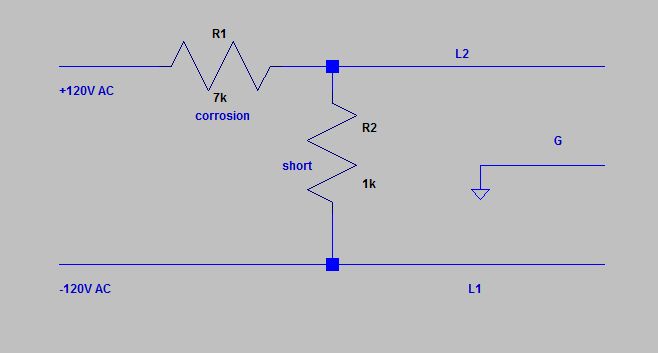
- One way to check that would be to scope the voltages together at L1 and L2 to observe that L1 and L2 are no more in phase opposition, but close to be in phase concordance. Also, it would be interesting to check the corrosion impedance of the L2 wire. In the schematic, I've given imaginary values, the point being that there is a ratio of 1:7 between the resistances:
- 30V = 240V / 8 = 240V / (1 + 7).
#5: Post edited
by
coquelicot
·
2020-08-02T18:35:55Z (almost 5 years ago)
- Well, here is was my logic tells me:
- The corrosion has caused a high impedance in the L2 wire, but there should be also a "short" between the L1 and L2 wire. So that the voltage between L1 and L2 falls to 30V, and the voltage between G and L1 is 90V. In other words:
- L1 - G = 120V = L1 - L2 + L2 - G = 30 + 90 = 120.
- In the shematic below, I've noted +120V AC and -120V AC just to say that the voltage is in phase opposition.
- 
One way to check that would be to scope the voltages together at L1 and L2 to observe that L1 and L2 are no more in phase opposition, but close to be in phase concordance. Also, it would be interesting to check the corrosion impedance of the L2 wire (in the schematic, I've given imaginary values, the point being that there is a ratio of 1:5 between the resistances).
- Well, here is was my logic tells me:
- The corrosion has caused a high impedance in the L2 wire, but there should be also a "short" between the L1 and L2 wire. So that the voltage between L1 and L2 falls to 30V, and the voltage between G and L1 is 90V. In other words:
- L1 - G = 120V = L1 - L2 + L2 - G = 30 + 90 = 120.
- In the shematic below, I've noted +120V AC and -120V AC just to say that the voltage is in phase opposition.
- 
- One way to check that would be to scope the voltages together at L1 and L2 to observe that L1 and L2 are no more in phase opposition, but close to be in phase concordance. Also, it would be interesting to check the corrosion impedance of the L2 wire. In the schematic, I've given imaginary values, the point being that there is a ratio of 1:7 between the resistances:
- 30V = 240V / 8 = 240V / (1 + 7).
#4: Post edited
by
coquelicot
·
2020-08-02T18:33:22Z (almost 5 years ago)
- Well, here is was my logic tells me:
- The corrosion has caused a high impedance in the L2 wire, but there should be also a "short" between the L1 and L2 wire. So that the voltage between L1 and L2 falls to 30V, and the voltage between G and L1 is 90V. In other words:
- L1 - G = 120V = L1 - L2 + L2 - G = 30 + 90 = 120.
- In the shematic below, I've noted +120V AC and -120V AC just to say that the voltage is in phase opposition.
- 
One way to check that would be to scope the voltages together at L1 and L2 to observe that L1 and L2 are no more in phase opposition, but close to be in phase concordance. Also, it would be interesting to check the corrosion impedance of the L2 wire (in the schematic, I've given imaginary values, the point being that there is a ration of 1:5 between the resistances).
- Well, here is was my logic tells me:
- The corrosion has caused a high impedance in the L2 wire, but there should be also a "short" between the L1 and L2 wire. So that the voltage between L1 and L2 falls to 30V, and the voltage between G and L1 is 90V. In other words:
- L1 - G = 120V = L1 - L2 + L2 - G = 30 + 90 = 120.
- In the shematic below, I've noted +120V AC and -120V AC just to say that the voltage is in phase opposition.
- 
- One way to check that would be to scope the voltages together at L1 and L2 to observe that L1 and L2 are no more in phase opposition, but close to be in phase concordance. Also, it would be interesting to check the corrosion impedance of the L2 wire (in the schematic, I've given imaginary values, the point being that there is a ratio of 1:5 between the resistances).
#3: Post edited
by
coquelicot
·
2020-08-02T18:32:43Z (almost 5 years ago)
- Well, here is was my logic tells me:
- The corrosion has caused a high impedance in the L2 wire, but there should be also a "short" between the L1 and L2 wire. So that the voltage between L1 and L2 falls to 30V, and the voltage between G and L1 is 90V. In other words:
- L1 - G = 120V = L1 - L2 + L2 - G = 30 + 90 = 120.
- In the shematic below, I've noted +120V AC and -120V AC just to say that the voltage is in phase opposition.
- 
- One way to check that would be to scope the voltages together at L1 and L2 to observe that L1 and L2 are no more in phase opposition, but close to be in phase concordance. Also, it would be interesting to check the corrosion impedance of the L2 wire (in the schematic, I've given imaginary values, the point being that there is a ration of 1:5 between the resistances).
#2: Post edited
by
coquelicot
·
2020-08-02T18:25:02Z (almost 5 years ago)
- Well, here is was my logic tells me:
- The corrosion has caused a high impedance in the L2 wire, but there should be also a "short" between the L1 and L2 wire. So that the voltage between L1 and L2 falls to 30V, and the voltage between G and L1 is 90V. In other words:
- L1 - G = 120V = L1 - L2 + L2 - G = 30 + 90 = 120.
- In the shematic below, I've noted +120V AC and -120V AC just to say that the voltage is in phase opposition.
- 
#1: Initial revision
by
coquelicot
·
2020-08-02T18:21:45Z (almost 5 years ago)
Well, here is was my logic tells me: The corrosion has caused a high impedance in the L2 wire, but there should be also a "short" between the L1 and L2 wire. So that the voltage between L1 and L2 falls to 30V, and the voltage between G and L1 is 90V. In other words: L1 - G = 120V = L1 - L2 + L2 - G = 30 + 90 = 120. In the shematic below, I've noted +120V AC and -120V AC just to say that the voltage is in phase opposition. 