Post History
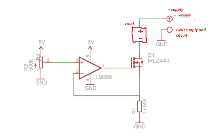
let me begin with a schematic for an adjustable current source with a simple load: The operation is simple: The current I inside R1 gives rise a voltage drop equal to I/R1 (= I if R1 = 1). So the ...
#5: Post edited
by
 coquelicot
·
2020-08-18T15:27:07Z (almost 5 years ago)
coquelicot
·
2020-08-18T15:27:07Z (almost 5 years ago)
- let me begin with a schematic for an adjustable current source with a simple load:
- 
- The operation is simple: The current I inside R1 gives rise a voltage drop equal to
- I/R1 (= I if R1 = 1).
- So the oamp will set the voltage to the gate of the mosfet in such a way that
- I/R1 = V_pot, that is, I = R1 V_pot = V_pot if R1 = 1.
- Since V_pot varies between 0 and 5V, I varies between 0 and 5 amp.
- So, the resistor should be rated for 25W (=1 ohm * (5A)^2 ) otherwise it will burn (assuming your supply and mosfet will not burn before it).
- I suggest to put a 500k resistor between the pot and the 5V supply, in order to make V_pot vary between 0 and 2.5V. In this way, the maximal power dissipated by the resistor will be about 5W.
Now, regarding the schematic you posted, it is not a constant current source for an usual load, but a constant current source for testing a battery, that is, the battery under test IS the power supply (and there is no load). That means that it should work up to 5V if the battery is able to feed 5A.- In this way, you can measure the maximal current the battery is able to deliver (or more precisely, if it fits its compliance), by simply measuring the voltage at R1 (recall that the voltage is equal to the current because R1 = 1Ohm).
- Normally, there is no reason the circuit do not work, except that you may have wired the oamp wrongly, or a perverse connection etc. Nevertheless, to religiously protect the oamp, I suggest to put a 1k resistor between the out of the oamp and the gate of the mosfet. This will also prevent possible destructive oscillations and everything should work fine.
- So, the improvements I suggest are:
- 1. 500k resistor between the pot and the 5V supply, or a resistor rated 25W.
- 2. 1k resistor between the out of the oamp and the gate of the mosfet
- 3. Oh, and of course a heat sink for the transistor, otherwise it may well burn.
- let me begin with a schematic for an adjustable current source with a simple load:
- 
- The operation is simple: The current I inside R1 gives rise a voltage drop equal to
- I/R1 (= I if R1 = 1).
- So the oamp will set the voltage to the gate of the mosfet in such a way that
- I/R1 = V_pot, that is, I = R1 V_pot = V_pot if R1 = 1.
- Since V_pot varies between 0 and 5V, I varies between 0 and 5 amp.
- So, the resistor should be rated for 25W (=1 ohm * (5A)^2 ) otherwise it will burn (assuming your supply and mosfet will not burn before it).
- I suggest to put a 500k resistor between the pot and the 5V supply, in order to make V_pot vary between 0 and 2.5V. In this way, the maximal power dissipated by the resistor will be about 5W.
- Now, regarding the schematic you posted, it is not a constant current source for an usual load, but a constant current source for testing a battery, that is, the battery under test IS the power supply (and there is no load). Apart from that, everything is the same. That means that it should work up to 5V if the battery is able to feed 5A.
- In this way, you can measure the maximal current the battery is able to deliver (or more precisely, if it fits its compliance), by simply measuring the voltage at R1 (recall that the voltage is equal to the current because R1 = 1Ohm).
- Normally, there is no reason the circuit do not work, except that you may have wired the oamp wrongly, or a perverse connection etc. Nevertheless, to religiously protect the oamp, I suggest to put a 1k resistor between the out of the oamp and the gate of the mosfet. This will also prevent possible destructive oscillations and everything should work fine.
- So, the improvements I suggest are:
- 1. 500k resistor between the pot and the 5V supply, or a resistor rated 25W.
- 2. 1k resistor between the out of the oamp and the gate of the mosfet
- 3. Oh, and of course a heat sink for the transistor, otherwise it may well burn.
#4: Post edited
by
coquelicot
·
2020-08-18T15:26:09Z (almost 5 years ago)
It is simple to understand how this circuit is supposed to work and what is wrong: Here is a schematic for an adjustable current source with a simple load:- 
- The operation is simple: The current I inside R1 gives rise a voltage drop equal to
- I/R1 (= I if R1 = 1).
- So the oamp will set the voltage to the gate of the mosfet in such a way that
- I/R1 = V_pot, that is, I = R1 V_pot = V_pot if R1 = 1.
- Since V_pot varies between 0 and 5V, I varies between 0 and 5 amp.
- So, the resistor should be rated for 25W (=1 ohm * (5A)^2 ) otherwise it will burn (assuming your supply and mosfet will not burn before it).
- I suggest to put a 500k resistor between the pot and the 5V supply, in order to make V_pot vary between 0 and 2.5V. In this way, the maximal power dissipated by the resistor will be about 5W.
- Now, regarding the schematic you posted, it is not a constant current source for an usual load, but a constant current source for testing a battery, that is, the battery under test IS the power supply (and there is no load). That means that it should work up to 5V if the battery is able to feed 5A.
- In this way, you can measure the maximal current the battery is able to deliver (or more precisely, if it fits its compliance), by simply measuring the voltage at R1 (recall that the voltage is equal to the current because R1 = 1Ohm).
- Normally, there is no reason the circuit do not work, except that you may have wired the oamp wrongly, or a perverse connection etc. Nevertheless, to religiously protect the oamp, I suggest to put a 1k resistor between the out of the oamp and the gate of the mosfet. This will also prevent possible destructive oscillations and everything should work fine.
- So, the improvements I suggest are:
- 1. 500k resistor between the pot and the 5V supply, or a resistor rated 25W.
- 2. 1k resistor between the out of the oamp and the gate of the mosfet
- 3. Oh, and of course a heat sink for the transistor, otherwise it may well burn.
- let me begin with a schematic for an adjustable current source with a simple load:
- 
- The operation is simple: The current I inside R1 gives rise a voltage drop equal to
- I/R1 (= I if R1 = 1).
- So the oamp will set the voltage to the gate of the mosfet in such a way that
- I/R1 = V_pot, that is, I = R1 V_pot = V_pot if R1 = 1.
- Since V_pot varies between 0 and 5V, I varies between 0 and 5 amp.
- So, the resistor should be rated for 25W (=1 ohm * (5A)^2 ) otherwise it will burn (assuming your supply and mosfet will not burn before it).
- I suggest to put a 500k resistor between the pot and the 5V supply, in order to make V_pot vary between 0 and 2.5V. In this way, the maximal power dissipated by the resistor will be about 5W.
- Now, regarding the schematic you posted, it is not a constant current source for an usual load, but a constant current source for testing a battery, that is, the battery under test IS the power supply (and there is no load). That means that it should work up to 5V if the battery is able to feed 5A.
- In this way, you can measure the maximal current the battery is able to deliver (or more precisely, if it fits its compliance), by simply measuring the voltage at R1 (recall that the voltage is equal to the current because R1 = 1Ohm).
- Normally, there is no reason the circuit do not work, except that you may have wired the oamp wrongly, or a perverse connection etc. Nevertheless, to religiously protect the oamp, I suggest to put a 1k resistor between the out of the oamp and the gate of the mosfet. This will also prevent possible destructive oscillations and everything should work fine.
- So, the improvements I suggest are:
- 1. 500k resistor between the pot and the 5V supply, or a resistor rated 25W.
- 2. 1k resistor between the out of the oamp and the gate of the mosfet
- 3. Oh, and of course a heat sink for the transistor, otherwise it may well burn.
#3: Post edited
by
coquelicot
·
2020-08-18T15:16:45Z (almost 5 years ago)
- It is simple to understand how this circuit is supposed to work and what is wrong: Here is a schematic for an adjustable current source with a simple load:
- 
- The operation is simple: The current I inside R1 gives rise a voltage drop equal to
- I/R1 (= I if R1 = 1).
- So the oamp will set the voltage to the gate of the mosfet in such a way that
- I/R1 = V_pot, that is, I = R1 V_pot = V_pot if R1 = 1.
- Since V_pot varies between 0 and 5V, I varies between 0 and 5 amp.
- So, the resistor should be rated for 25W (=1 ohm * (5A)^2 ) otherwise it will burn (assuming your supply and mosfet will not burn before it).
- I suggest to put a 500k resistor between the pot and the 5V supply, in order to make V_pot vary between 0 and 2.5V. In this way, the maximal power dissipated by the resistor will be about 5W.
- Now, regarding the schematic you posted, it is not a constant current source for an usual load, but a constant current source for testing a battery, that is, the battery under test IS the power supply (and there is no load). That means that it should work up to 5V if the battery is able to feed 5A.
In this way, you can measure the maximal current the battery is able to deliver (or more precisely, if it fit its compliance), by simply measuring the voltage at R1 (recall that the voltage is equal to the current because R1 = 1Ohm).- Normally, there is no reason the circuit do not work, except that you may have wired the oamp wrongly, or a perverse connection etc. Nevertheless, to religiously protect the oamp, I suggest to put a 1k resistor between the out of the oamp and the gate of the mosfet. This will also prevent possible destructive oscillations and everything should work fine.
- So, the improvements I suggest are:
- 1. 500k resistor between the pot and the 5V supply, or a resistor rated 25W.
- 2. 1k resistor between the out of the oamp and the gate of the mosfet
- 3. Oh, and of course a heat sink for the transistor, otherwise it may well burn.
- It is simple to understand how this circuit is supposed to work and what is wrong: Here is a schematic for an adjustable current source with a simple load:
- 
- The operation is simple: The current I inside R1 gives rise a voltage drop equal to
- I/R1 (= I if R1 = 1).
- So the oamp will set the voltage to the gate of the mosfet in such a way that
- I/R1 = V_pot, that is, I = R1 V_pot = V_pot if R1 = 1.
- Since V_pot varies between 0 and 5V, I varies between 0 and 5 amp.
- So, the resistor should be rated for 25W (=1 ohm * (5A)^2 ) otherwise it will burn (assuming your supply and mosfet will not burn before it).
- I suggest to put a 500k resistor between the pot and the 5V supply, in order to make V_pot vary between 0 and 2.5V. In this way, the maximal power dissipated by the resistor will be about 5W.
- Now, regarding the schematic you posted, it is not a constant current source for an usual load, but a constant current source for testing a battery, that is, the battery under test IS the power supply (and there is no load). That means that it should work up to 5V if the battery is able to feed 5A.
- In this way, you can measure the maximal current the battery is able to deliver (or more precisely, if it fits its compliance), by simply measuring the voltage at R1 (recall that the voltage is equal to the current because R1 = 1Ohm).
- Normally, there is no reason the circuit do not work, except that you may have wired the oamp wrongly, or a perverse connection etc. Nevertheless, to religiously protect the oamp, I suggest to put a 1k resistor between the out of the oamp and the gate of the mosfet. This will also prevent possible destructive oscillations and everything should work fine.
- So, the improvements I suggest are:
- 1. 500k resistor between the pot and the 5V supply, or a resistor rated 25W.
- 2. 1k resistor between the out of the oamp and the gate of the mosfet
- 3. Oh, and of course a heat sink for the transistor, otherwise it may well burn.
#2: Post edited
by
coquelicot
·
2020-08-18T15:14:28Z (almost 5 years ago)
- It is simple to understand how this circuit is supposed to work and what is wrong: Here is a schematic for an adjustable current source with a simple load:
- 
- The operation is simple: The current I inside R1 gives rise a voltage drop equal to
- I/R1 (= I if R1 = 1).
- So the oamp will set the voltage to the gate of the mosfet in such a way that
- I/R1 = V_pot, that is, I = R1 V_pot = V_pot if R1 = 1.
- Since V_pot varies between 0 and 5V, I varies between 0 and 5 amp.
- So, the resistor should be rated for 25W (=1 ohm * (5A)^2 ) otherwise it will burn (assuming your supply and mosfet will not burn before it).
- I suggest to put a 500k resistor between the pot and the 5V supply, in order to make V_pot vary between 0 and 2.5V. In this way, the maximal power dissipated by the resistor will be about 5W.
Now, regarding the schematic you posted, it is not a constant current source for an usual load, but a constant current source for testing a battery, that is, the battery under test IS the power supply. That means that it should work up to 5V if the battery is able to feed 5A.- In this way, you can measure the maximal current the battery is able to deliver (or more precisely, if it fit its compliance), by simply measuring the voltage at R1 (recall that the voltage is equal to the current because R1 = 1Ohm).
- Normally, there is no reason the circuit do not work, except that you may have wired the oamp wrongly, or a perverse connection etc. Nevertheless, to religiously protect the oamp, I suggest to put a 1k resistor between the out of the oamp and the gate of the mosfet. This will also prevent possible destructive oscillations and everything should work fine.
- It is simple to understand how this circuit is supposed to work and what is wrong: Here is a schematic for an adjustable current source with a simple load:
- 
- The operation is simple: The current I inside R1 gives rise a voltage drop equal to
- I/R1 (= I if R1 = 1).
- So the oamp will set the voltage to the gate of the mosfet in such a way that
- I/R1 = V_pot, that is, I = R1 V_pot = V_pot if R1 = 1.
- Since V_pot varies between 0 and 5V, I varies between 0 and 5 amp.
- So, the resistor should be rated for 25W (=1 ohm * (5A)^2 ) otherwise it will burn (assuming your supply and mosfet will not burn before it).
- I suggest to put a 500k resistor between the pot and the 5V supply, in order to make V_pot vary between 0 and 2.5V. In this way, the maximal power dissipated by the resistor will be about 5W.
- Now, regarding the schematic you posted, it is not a constant current source for an usual load, but a constant current source for testing a battery, that is, the battery under test IS the power supply (and there is no load). That means that it should work up to 5V if the battery is able to feed 5A.
- In this way, you can measure the maximal current the battery is able to deliver (or more precisely, if it fit its compliance), by simply measuring the voltage at R1 (recall that the voltage is equal to the current because R1 = 1Ohm).
- Normally, there is no reason the circuit do not work, except that you may have wired the oamp wrongly, or a perverse connection etc. Nevertheless, to religiously protect the oamp, I suggest to put a 1k resistor between the out of the oamp and the gate of the mosfet. This will also prevent possible destructive oscillations and everything should work fine.
- So, the improvements I suggest are:
- 1. 500k resistor between the pot and the 5V supply, or a resistor rated 25W.
- 2. 1k resistor between the out of the oamp and the gate of the mosfet
- 3. Oh, and of course a heat sink for the transistor, otherwise it may well burn.
#1: Initial revision
by
coquelicot
·
2020-08-18T15:09:49Z (almost 5 years ago)
It is simple to understand how this circuit is supposed to work and what is wrong: Here is a schematic for an adjustable current source with a simple load:  The operation is simple: The current I inside R1 gives rise a voltage drop equal to I/R1 (= I if R1 = 1). So the oamp will set the voltage to the gate of the mosfet in such a way that I/R1 = V_pot, that is, I = R1 V_pot = V_pot if R1 = 1. Since V_pot varies between 0 and 5V, I varies between 0 and 5 amp. So, the resistor should be rated for 25W (=1 ohm * (5A)^2 ) otherwise it will burn (assuming your supply and mosfet will not burn before it). I suggest to put a 500k resistor between the pot and the 5V supply, in order to make V_pot vary between 0 and 2.5V. In this way, the maximal power dissipated by the resistor will be about 5W. Now, regarding the schematic you posted, it is not a constant current source for an usual load, but a constant current source for testing a battery, that is, the battery under test IS the power supply. That means that it should work up to 5V if the battery is able to feed 5A. In this way, you can measure the maximal current the battery is able to deliver (or more precisely, if it fit its compliance), by simply measuring the voltage at R1 (recall that the voltage is equal to the current because R1 = 1Ohm). Normally, there is no reason the circuit do not work, except that you may have wired the oamp wrongly, or a perverse connection etc. Nevertheless, to religiously protect the oamp, I suggest to put a 1k resistor between the out of the oamp and the gate of the mosfet. This will also prevent possible destructive oscillations and everything should work fine.