Post History
Here is the bootstrapping technique for opamps, as exposed in the Art of Electronics:. This technique is supposed to increase considerably the input impedance of the opamp for an AC input source (...
#8: Post edited
by
 Lorenzo Donati
·
2023-08-11T12:03:33Z (almost 2 years ago)
Lorenzo Donati
·
2023-08-11T12:03:33Z (almost 2 years ago)
Corrected use of "non-standard" (hence unclear) abbreviation for operational amplifier.
Design rules for oamp bootstrap
- Design rules for opamp bootstrapping
#7: Post edited
by
Lorenzo Donati
·
2023-08-11T12:00:18Z (almost 2 years ago)
Retagged. Corrected use of "non-standard" (hence unclear) abbreviation for operational amplifier.
Here is the bootstrapping technique for oamps, as exposed in the Art of Electronics: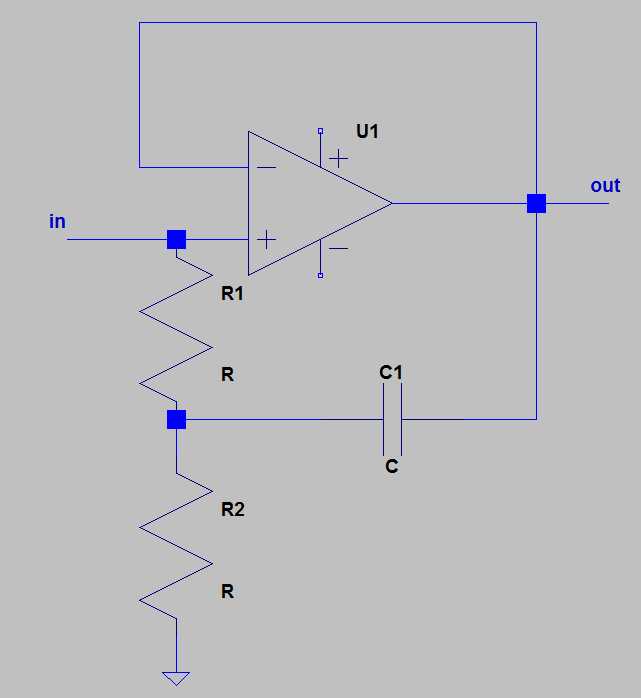.This technique is supposed to increase considerably the input impedance of the oamp for an AC input source (usually passed through a cap).The Art of Electronics considers it somewhat outdated, as it is now possible to use extremely low bias input current oamps.I disagree with him: I see no reason to buy a somewhat expensive femtoamp oamp when you can obtain the same result with a more banal one (as long as we deal with AC sources).- Actually I do have an application where I use the self capacitance of a rotating half cylinder to measure the ambient electric field, which is perfectly tailored to bootstrapping.
- Now, to make my question precise:
- Assume
- 1. I have an AC sinusoidal source of known frequency w;
- 2. I want the output signal (voltage) be at least n percents of the input signal (e.g. 99%);
- 3. I want the RMS input current be equal to at most I_max.
- **Question**: how should I choose the values of the two resistors and of the capacitor in the schematic above?
- **Edit**: Here is a simulation done with LT spice. I've more or less given random values, following nothing but some intuitive guess:
- Simulation with bootstrap:
- 
- Result (current through the sine generator):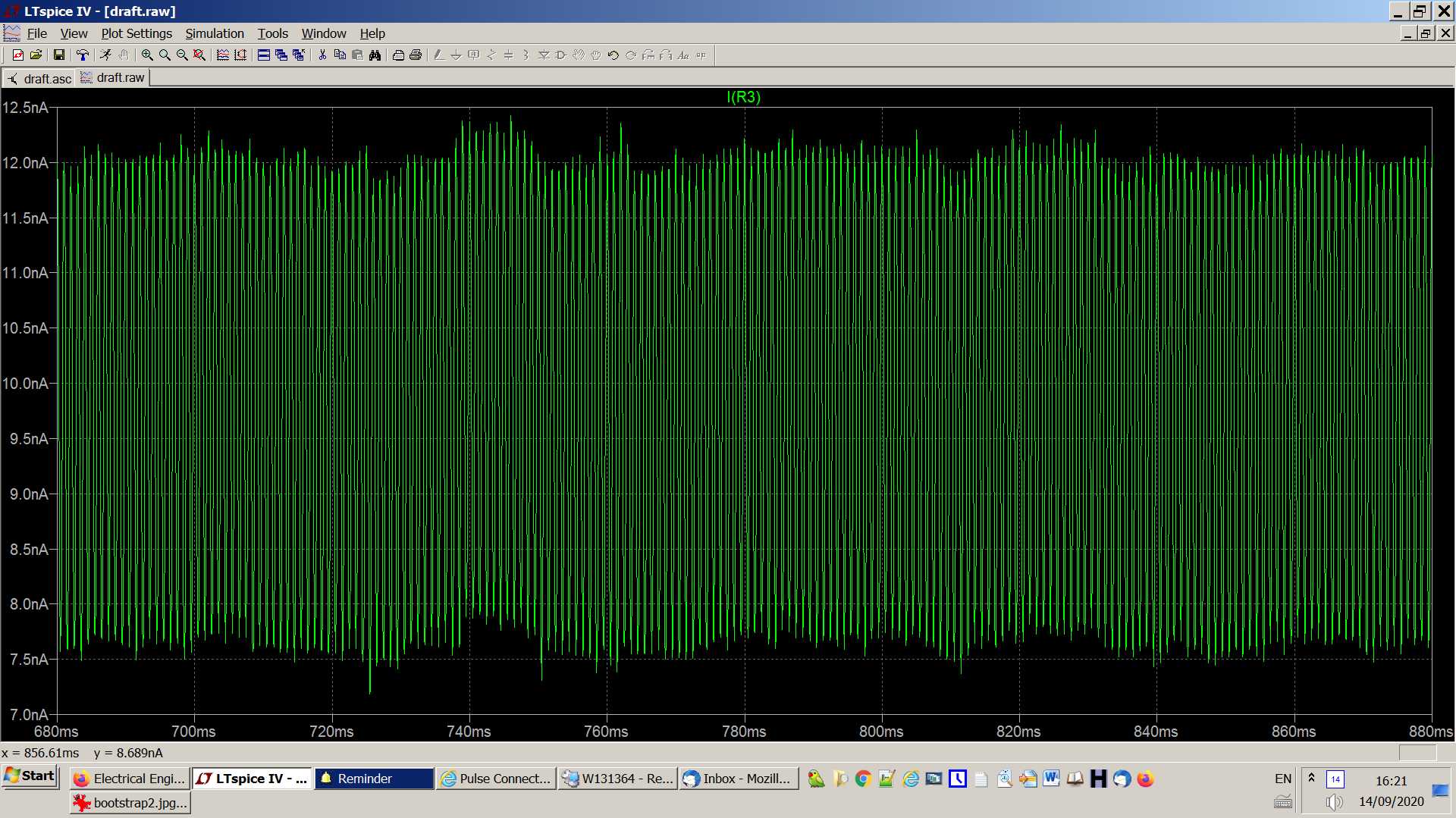
- Result of the same simulation but without cap C1:
- 
- **Edit 2:**
- Perhaps the schematic will make more sense if we pass the input signal through a capacitor, as is usually the case.
- Here is the schematic for the simulation:
- 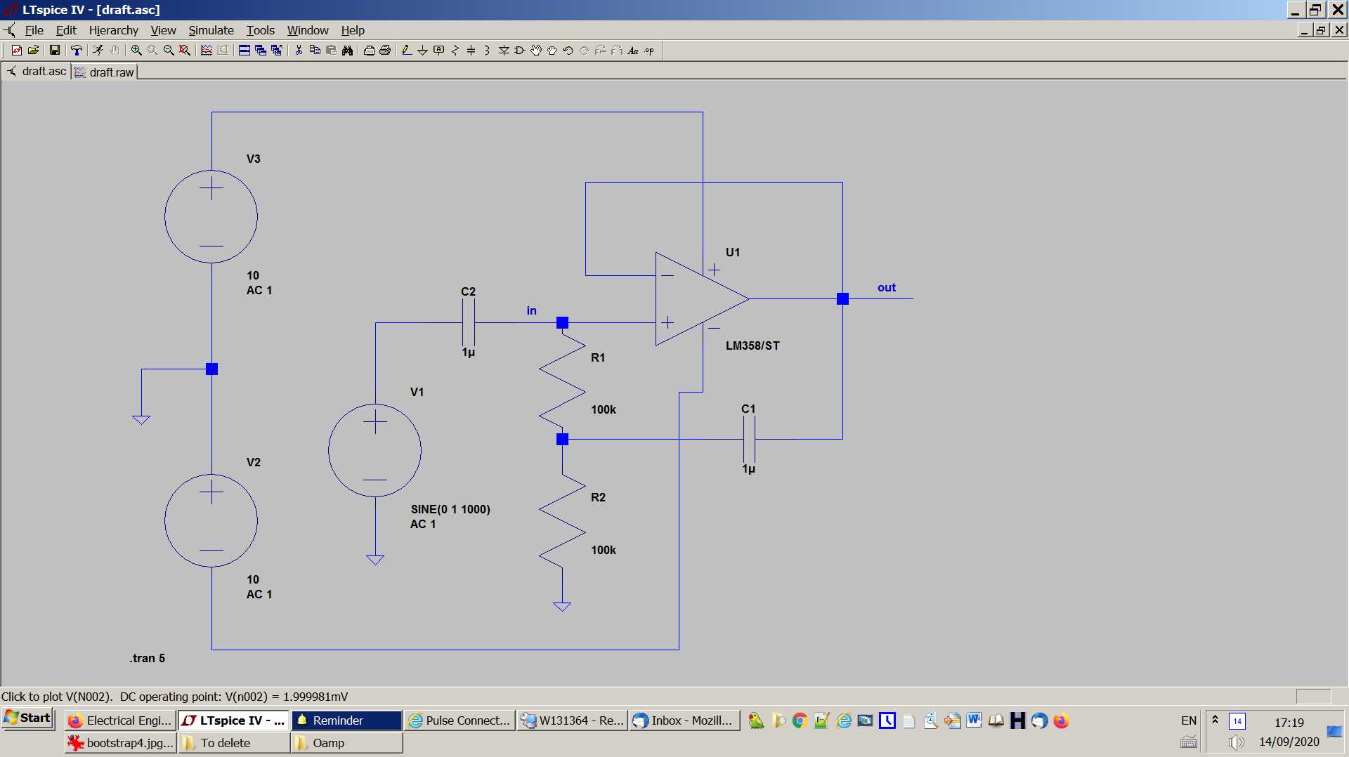
And here are the results: the first trace is the current through cap C2, and the second trace is the current at the in+ of the oamp:- 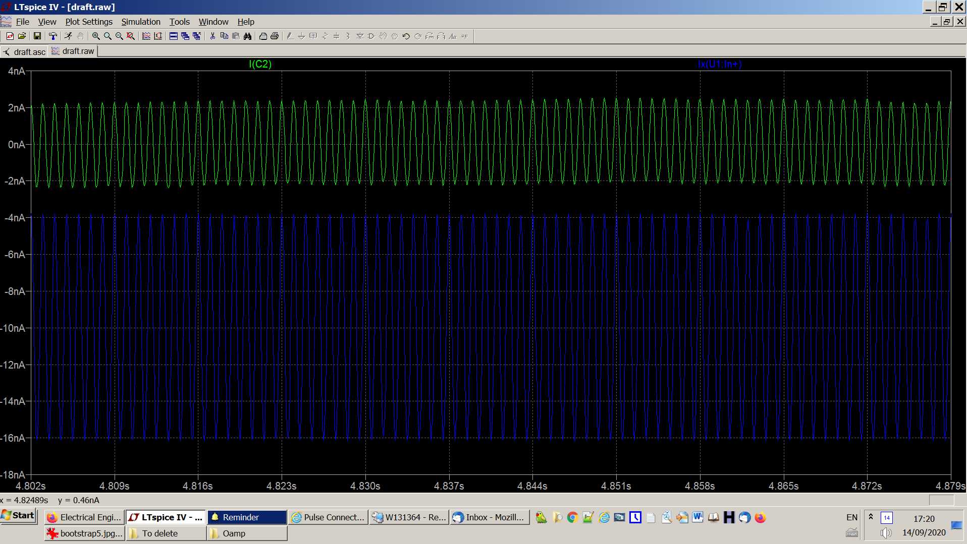
- So, we see that the amplitude of the current through C2 is about 2nA, and the amplitude of the AC current at in+ is 6nA, more than I_C2.
- Without cap C1, the current through the sine generator (and hence through C2) is the same as previously
- Here is the bootstrapping technique for opamps, as exposed in the Art of Electronics:.
- This technique is supposed to increase considerably the input impedance of the opamp for an AC input source (usually passed through a cap).
- The Art of Electronics considers it somewhat outdated, as it is now possible to use extremely low bias input current opamps.
- I disagree with him: I see no reason to buy a somewhat expensive femtoamp opamp when you can obtain the same result with a more banal one (as long as we deal with AC sources).
- Actually I do have an application where I use the self capacitance of a rotating half cylinder to measure the ambient electric field, which is perfectly tailored to bootstrapping.
- Now, to make my question precise:
- Assume
- 1. I have an AC sinusoidal source of known frequency w;
- 2. I want the output signal (voltage) be at least n percents of the input signal (e.g. 99%);
- 3. I want the RMS input current be equal to at most I_max.
- **Question**: how should I choose the values of the two resistors and of the capacitor in the schematic above?
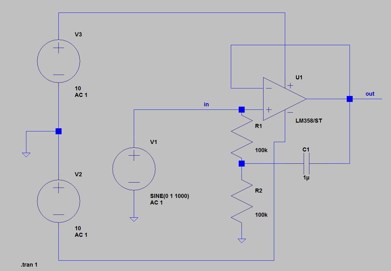
- **Edit**: Here is a simulation done with LT spice. I've more or less given random values, following nothing but some intuitive guess:
- Simulation with bootstrap:
- 
- Result (current through the sine generator):
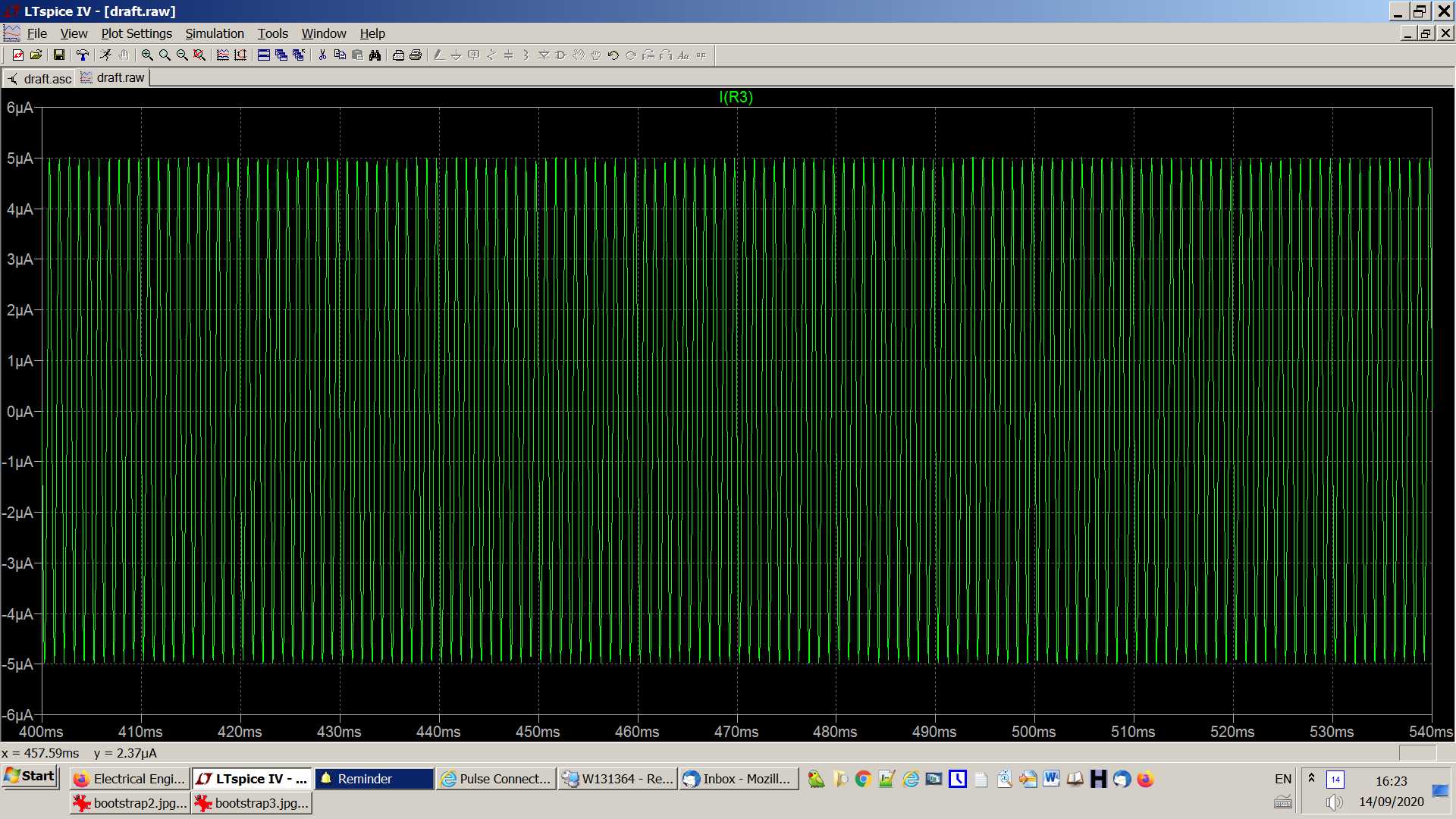
- Result of the same simulation but without cap C1:
- 
- **Edit 2:**
- Perhaps the schematic will make more sense if we pass the input signal through a capacitor, as is usually the case.
- Here is the schematic for the simulation:
- 
- And here are the results: the first trace is the current through cap C2, and the second trace is the current at the in+ of the opamp:
- 
- So, we see that the amplitude of the current through C2 is about 2nA, and the amplitude of the AC current at in+ is 6nA, more than I_C2.
- Without cap C1, the current through the sine generator (and hence through C2) is the same as previously
#6: Post edited
by
 coquelicot
·
2020-09-14T14:28:00Z (over 4 years ago)
coquelicot
·
2020-09-14T14:28:00Z (over 4 years ago)
- Here is the bootstrapping technique for oamps, as exposed in the Art of Electronics:.
- This technique is supposed to increase considerably the input impedance of the oamp for an AC input source (usually passed through a cap).
- The Art of Electronics considers it somewhat outdated, as it is now possible to use extremely low bias input current oamps.
- I disagree with him: I see no reason to buy a somewhat expensive femtoamp oamp when you can obtain the same result with a more banal one (as long as we deal with AC sources).
- Actually I do have an application where I use the self capacitance of a rotating half cylinder to measure the ambient electric field, which is perfectly tailored to bootstrapping.
- Now, to make my question precise:
- Assume
- 1. I have an AC sinusoidal source of known frequency w;
- 2. I want the output signal (voltage) be at least n percents of the input signal (e.g. 99%);
- 3. I want the RMS input current be equal to at most I_max.
- **Question**: how should I choose the values of the two resistors and of the capacitor in the schematic above?
- **Edit**: Here is a simulation done with LT spice. I've more or less given random values, following nothing but some intuitive guess:
- Simulation with bootstrap:
- 
- Result (current through the sine generator):
- Result of the same simulation but without cap C1:
- 
- **Edit 2:**
- Perhaps the schematic will make more sense if we pass the input signal through a capacitor, as is usually the case.
- Here is the schematic for the simulation:
- 
- And here are the results: the first trace is the current through cap C2, and the second trace is the current at the in+ of the oamp:
- 
So, we see that the amplitude of the current through C2 is about 2nA, and the amplitude of the AC current at in+ is 6nA, more than I_C2.
- Here is the bootstrapping technique for oamps, as exposed in the Art of Electronics:.
- This technique is supposed to increase considerably the input impedance of the oamp for an AC input source (usually passed through a cap).
- The Art of Electronics considers it somewhat outdated, as it is now possible to use extremely low bias input current oamps.
- I disagree with him: I see no reason to buy a somewhat expensive femtoamp oamp when you can obtain the same result with a more banal one (as long as we deal with AC sources).
- Actually I do have an application where I use the self capacitance of a rotating half cylinder to measure the ambient electric field, which is perfectly tailored to bootstrapping.
- Now, to make my question precise:
- Assume
- 1. I have an AC sinusoidal source of known frequency w;
- 2. I want the output signal (voltage) be at least n percents of the input signal (e.g. 99%);
- 3. I want the RMS input current be equal to at most I_max.
- **Question**: how should I choose the values of the two resistors and of the capacitor in the schematic above?
- **Edit**: Here is a simulation done with LT spice. I've more or less given random values, following nothing but some intuitive guess:
- Simulation with bootstrap:
- 
- Result (current through the sine generator):
- Result of the same simulation but without cap C1:
- 
- **Edit 2:**
- Perhaps the schematic will make more sense if we pass the input signal through a capacitor, as is usually the case.
- Here is the schematic for the simulation:
- 
- And here are the results: the first trace is the current through cap C2, and the second trace is the current at the in+ of the oamp:
- 
- So, we see that the amplitude of the current through C2 is about 2nA, and the amplitude of the AC current at in+ is 6nA, more than I_C2.
- Without cap C1, the current through the sine generator (and hence through C2) is the same as previously
#5: Post edited
by
coquelicot
·
2020-09-14T14:25:23Z (over 4 years ago)
- Here is the bootstrapping technique for oamps, as exposed in the Art of Electronics:.
- This technique is supposed to increase considerably the input impedance of the oamp for an AC input source (usually passed through a cap).
- The Art of Electronics considers it somewhat outdated, as it is now possible to use extremely low bias input current oamps.
- I disagree with him: I see no reason to buy a somewhat expensive femtoamp oamp when you can obtain the same result with a more banal one (as long as we deal with AC sources).
- Actually I do have an application where I use the self capacitance of a rotating half cylinder to measure the ambient electric field, which is perfectly tailored to bootstrapping.
- Now, to make my question precise:
- Assume
- 1. I have an AC sinusoidal source of known frequency w;
- 2. I want the output signal (voltage) be at least n percents of the input signal (e.g. 99%);
- 3. I want the RMS input current be equal to at most I_max.
- **Question**: how should I choose the values of the two resistors and of the capacitor in the schematic above?
- **Edit**: Here is a simulation done with LT spice. I've more or less given random values, following nothing but some intuitive guess:
- Simulation with bootstrap:
- 
- Result (current through the sine generator):
- Result of the same simulation but without cap C1:
- 
- **Edit 2:**
- Perhaps the schematic will make more sense if we pass the input signal through a capacitor, as is usually the case.
- Here is the schematic for the simulation:
- 
- And here are the results: the first trace is the current through cap C2, and the second trace is the current at the in+ of the oamp:
- 
- So, we see that the amplitude of the current through C2 is about 2nA, and the amplitude of the AC current at in+ is 6nA, more than I_C2.
#4: Post edited
by
coquelicot
·
2020-09-14T13:40:27Z (over 4 years ago)
- Here is the bootstrapping technique for oamps, as exposed in the Art of Electronics:.
- This technique is supposed to increase considerably the input impedance of the oamp for an AC input source (usually passed through a cap).
- The Art of Electronics considers it somewhat outdated, as it is now possible to use extremely low bias input current oamps.
- I disagree with him: I see no reason to buy a somewhat expensive femtoamp oamp when you can obtain the same result with a more banal one (as long as we deal with AC sources).
- Actually I do have an application where I use the self capacitance of a rotating half cylinder to measure the ambient electric field, which is perfectly tailored to bootstrapping.
- Now, to make my question precise:
- Assume
- 1. I have an AC sinusoidal source of known frequency w;
- 2. I want the output signal (voltage) be at least n percents of the input signal (e.g. 99%);
- 3. I want the RMS input current be equal to at most I_max.
- **Question**: how should I choose the values of the two resistors and of the capacitor in the schematic above?
- **Edit**: Here is a simulation done with LT spice. I've more or less given random values, following nothing but some intuitive guess:
- Simulation with bootstrap:
- 
Result:- Result of the same simulation but without cap C1:
- 
- Here is the bootstrapping technique for oamps, as exposed in the Art of Electronics:.
- This technique is supposed to increase considerably the input impedance of the oamp for an AC input source (usually passed through a cap).
- The Art of Electronics considers it somewhat outdated, as it is now possible to use extremely low bias input current oamps.
- I disagree with him: I see no reason to buy a somewhat expensive femtoamp oamp when you can obtain the same result with a more banal one (as long as we deal with AC sources).
- Actually I do have an application where I use the self capacitance of a rotating half cylinder to measure the ambient electric field, which is perfectly tailored to bootstrapping.
- Now, to make my question precise:
- Assume
- 1. I have an AC sinusoidal source of known frequency w;
- 2. I want the output signal (voltage) be at least n percents of the input signal (e.g. 99%);
- 3. I want the RMS input current be equal to at most I_max.
- **Question**: how should I choose the values of the two resistors and of the capacitor in the schematic above?
- **Edit**: Here is a simulation done with LT spice. I've more or less given random values, following nothing but some intuitive guess:
- Simulation with bootstrap:
- 
- Result (current through the sine generator):
- Result of the same simulation but without cap C1:
- 
#3: Post edited
by
coquelicot
·
2020-09-14T13:38:35Z (over 4 years ago)
- Here is the bootstrapping technique for oamps, as exposed in the Art of Electronics:.
- This technique is supposed to increase considerably the input impedance of the oamp for an AC input source (usually passed through a cap).
- The Art of Electronics considers it somewhat outdated, as it is now possible to use extremely low bias input current oamps.
- I disagree with him: I see no reason to buy a somewhat expensive femtoamp oamp when you can obtain the same result with a more banal one (as long as we deal with AC sources).
- Actually I do have an application where I use the self capacitance of a rotating half cylinder to measure the ambient electric field, which is perfectly tailored to bootstrapping.
- Now, to make my question precise:
- Assume
- 1. I have an AC sinusoidal source of known frequency w;
- 2. I want the output signal (voltage) be at least n percents of the input signal (e.g. 99%);
- 3. I want the RMS input current be equal to at most I_max.
- **Question**: how should I choose the values of the two resistors and of the capacitor in the schematic above?
- **Edit**: Here is a simulation done with LT spice. I've more or less given random values, following nothing but some intuitive guess:
- Simulation with bootstrap:
- 
- Result:
- Result of the same simulation but without cap C1:
- 
#2: Post edited
by
coquelicot
·
2020-09-14T11:07:33Z (over 4 years ago)
- Here is the bootstrapping technique for oamps, as exposed in the Art of Electronics:.
- This technique is supposed to increase considerably the input impedance of the oamp for an AC input source (usually passed through a cap).
- The Art of Electronics considers it somewhat outdated, as it is now possible to use extremely low bias input current oamps.
- I disagree with him: I see no reason to buy a somewhat expensive femtoamp oamp when you can obtain the same result with a more banal one (as long as we deal with AC sources).
- Actually I do have an application where I use the self capacitance of a rotating half cylinder to measure the ambient electric field, which is perfectly tailored to bootstrapping.
- Now, to make my question precise:
- Assume
- 1. I have an AC sinusoidal source of known frequency w;
2. I want the output signal (voltage) be n percents of the input signal (e.g. 99%);- 3. I want the RMS input current be equal to at most I_max.
- **Question**: how should I choose the values of the two resistors and of the capacitor in the schematic above?
- Here is the bootstrapping technique for oamps, as exposed in the Art of Electronics:.
- This technique is supposed to increase considerably the input impedance of the oamp for an AC input source (usually passed through a cap).
- The Art of Electronics considers it somewhat outdated, as it is now possible to use extremely low bias input current oamps.
- I disagree with him: I see no reason to buy a somewhat expensive femtoamp oamp when you can obtain the same result with a more banal one (as long as we deal with AC sources).
- Actually I do have an application where I use the self capacitance of a rotating half cylinder to measure the ambient electric field, which is perfectly tailored to bootstrapping.
- Now, to make my question precise:
- Assume
- 1. I have an AC sinusoidal source of known frequency w;
- 2. I want the output signal (voltage) be at least n percents of the input signal (e.g. 99%);
- 3. I want the RMS input current be equal to at most I_max.
- **Question**: how should I choose the values of the two resistors and of the capacitor in the schematic above?
#1: Initial revision
by
coquelicot
·
2020-09-14T11:04:33Z (over 4 years ago)
Design rules for oamp bootstrap
Here is the bootstrapping technique for oamps, as exposed in the Art of Electronics:. This technique is supposed to increase considerably the input impedance of the oamp for an AC input source (usually passed through a cap). The Art of Electronics considers it somewhat outdated, as it is now possible to use extremely low bias input current oamps. I disagree with him: I see no reason to buy a somewhat expensive femtoamp oamp when you can obtain the same result with a more banal one (as long as we deal with AC sources). Actually I do have an application where I use the self capacitance of a rotating half cylinder to measure the ambient electric field, which is perfectly tailored to bootstrapping. Now, to make my question precise: Assume 1. I have an AC sinusoidal source of known frequency w; 2. I want the output signal (voltage) be n percents of the input signal (e.g. 99%); 3. I want the RMS input current be equal to at most I_max. **Question**: how should I choose the values of the two resistors and of the capacitor in the schematic above?