Post History
$$\boxed{\text{What maximum value of } I_{OUT} \text{ did you have in mind?}}$$ Using $I_{OUT}$ and $V_{OUT}$ we calculate power uplift. Using power uplift and switching frequency, we calculate how...
#5: Post edited
by
 Andy aka
·
2020-09-26T16:46:29Z (over 4 years ago)
Andy aka
·
2020-09-26T16:46:29Z (over 4 years ago)
What maximum value of \$I_{OUT}\$ did you have in mind? It all starts with this value. From that value (and knowing the required \$V_{OUT}\$) we then know what power needs to be delivered to the load. Knowing load power and switching frequency we can say how much energy the inductor needs to store (and transfer) in each switching cycle. In other words: -$$\text{Energy (W) per cycle} = \dfrac{\text{Power Uplift}}{F_{SW}}$$<sub>power uplift is \$I_{OUT}\cdot(V_{OUT}-V_{IN})\$</sub>$$$$Assuming the boost converter will work in DCM, from the energy-per-cycle figure, we can determine how much peak current needs to be drawn through the boost converter's inductor because: -$$\text{Energy (W) per cycle} = \dfrac{1}{2}\cdot LI_{PK}^2$$<sub>I can't say if the boost converter should operate in DCM or CCM without knowing what \$I_{OUT}\$ is. So, you need to come clean on this. If it operates in CCM then the calculations are slightly different to DCM (see [this Q and A](https://electrical.codidact.com/questions/276224) on how boost converters work).</sub>- $$$$
This then dictates how large in value we set R1 in order to operate correctly with the protective current limiting circuit of the chip.- -----
If you know it operates in DCM, you can run through the above calculations and estimate \$I_{PK}\$ in the inductor (all based on knowing \$I_{OUT}\$). Then you will know how much voltage will be dropped across the MOSFET when it is active. If you then want to calculate R1, the data sheet should have the information but please do leave a comment if you need further assistance on this.- -----
Taking a stab at what information is contained in the question we might see it operate in DCM if the load is 3 kohm and the switching frequency is 10 kHz: -- $$$$
- 
- \$I_{PK}\$ would be 3.027 amps and, with an RDS of 0.55 ohms, the volt drop would be about 1.7 volts. Personally speaking I think you could find a more suitable MOSFET with slightly lower on resistance (circa 0.1 ohms) that was OK to run up to 300 volts. Given that the output is set to be 180 volts, that shouldn't be a problem.
- $$\boxed{\text{What maximum value of } I_{OUT} \text{ did you have in mind?}}$$
- Using \$I_{OUT}\$ and \$V_{OUT}\$ we calculate power uplift. Using power uplift and switching frequency, we calculate how much energy the inductor needs to store (and transfer) in each switching cycle: -
- $$\text{Power uplift is:} \hspace{1cm}I_{OUT}\cdot(V_{OUT}-V_{IN})$$
- $$\text{Energy per switching cycle} = \dfrac{\text{Power Uplift}}{F_{SW}}$$
- Assuming the boost converter will work in DCM, we can determine how much peak current needs to be drawn through the boost converter's inductor because: -
- $$\text{Energy per switching cycle} = \dfrac{1}{2}\cdot LI_{PK}^2$$
- <sub>However, I can't say if the boost converter should operate in DCM or CCM without knowing what \$I_{OUT}\$ is. So, you need to come clean on this. If it operates in CCM then the calculations are slightly different to DCM (see [this Q and A](https://electrical.codidact.com/questions/276224) on how boost converters work).</sub>
- $$$$
- This then dictates how large in value we set R1 in order to "set" the protective current limiting circuit of the chip.
- -----
- If you know it operates in DCM, you can run through the above calculations and estimate \$I_{PK}\$ in the inductor (all based on knowing \$I_{OUT}\$). Then you will know how much voltage will be dropped across the MOSFET when it is "on". If you then want to calculate R1, the data sheet should have the information but please do leave a comment if you need further assistance on this.
- -----
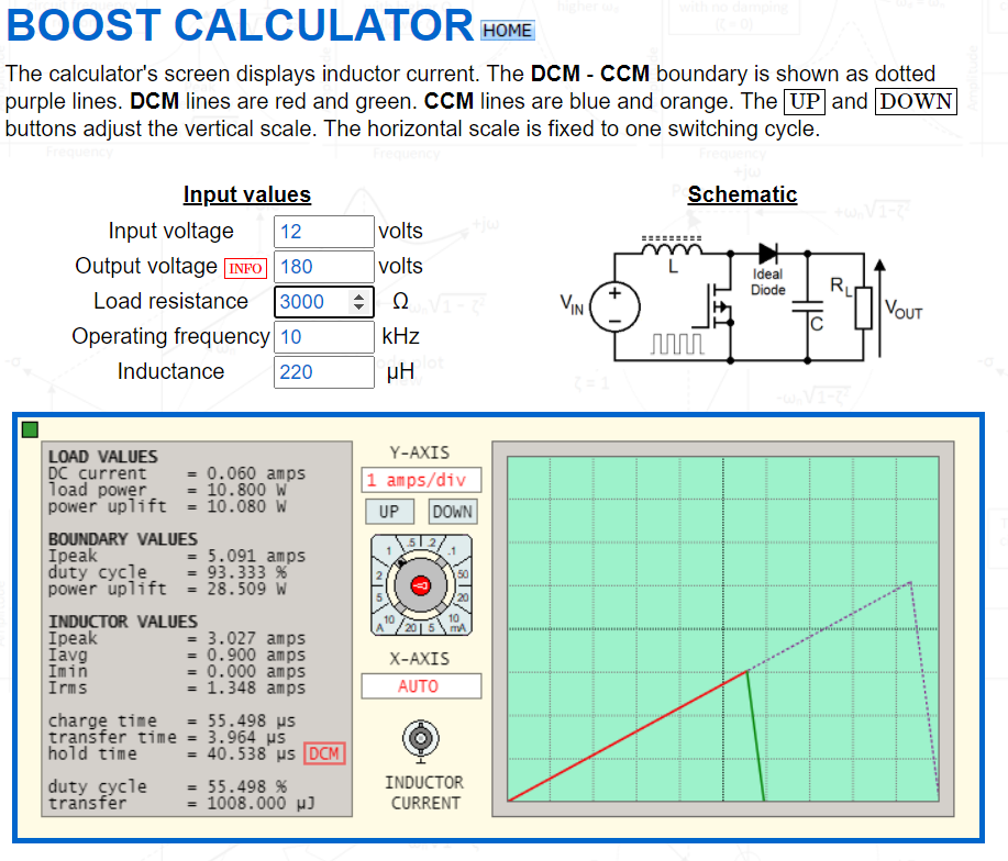
- Taking a stab at what information is contained in the question would see it operate in DCM if the load is 3 kohm and the switching frequency is 10 kHz: -
- $$$$
- 
- [Calculator hyperlink](http://www.stades.co.uk/Boost%20converter/Boost%20calculator.html).
- \$I_{PK}\$ would be 3.027 amps and, with an RDS of 0.55 ohms, the volt drop would be about 1.7 volts. Personally speaking I think you could find a more suitable MOSFET with slightly lower on resistance (circa 0.1 ohms) that was OK to run up to 300 volts. Given that the output is set to be 180 volts, that shouldn't be a problem.
#4: Post edited
by
Andy aka
·
2020-09-26T13:08:24Z (over 4 years ago)
What maximum value of \$I_{OUT}\$ did you have in mind? It all starts with this value. From that value (and knowing the required \$V_{OUT}\$) we then know what power needs to be delivered to the load. Knowing load power and switching frequency we can say how much energy the inductor needs to store (and deliver) each switching cycle. In other words: -$$\text{Energy (W)} = \dfrac{\text{Power Out}}{F_{SW}}$$Assuming the boost converter will work in DCM, from the energy/cycle we can determine how much peak current needs to be drawn through the boost converter's inductor because: -$$\text{Energy (W)} = \dfrac{1}{2}\cdot LI_{PK}^2$$- <sub>I can't say if the boost converter should operate in DCM or CCM without knowing what \$I_{OUT}\$ is. So, you need to come clean on this. If it operates in CCM then the calculations are slightly different to DCM (see [this Q and A](https://electrical.codidact.com/questions/276224) on how boost converters work).</sub>
- $$$$
- This then dictates how large in value we set R1 in order to operate correctly with the protective current limiting circuit of the chip.
- -----
- If you know it operates in DCM, you can run through the above calculations and estimate \$I_{PK}\$ in the inductor (all based on knowing \$I_{OUT}\$). Then you will know how much voltage will be dropped across the MOSFET when it is active. If you then want to calculate R1, the data sheet should have the information but please do leave a comment if you need further assistance on this.
- -----
- Taking a stab at what information is contained in the question we might see it operate in DCM if the load is 3 kohm and the switching frequency is 10 kHz: -
- $$$$
- 
- \$I_{PK}\$ would be 3.027 amps and, with an RDS of 0.55 ohms, the volt drop would be about 1.7 volts. Personally speaking I think you could find a more suitable MOSFET with slightly lower on resistance (circa 0.1 ohms) that was OK to run up to 300 volts. Given that the output is set to be 180 volts, that shouldn't be a problem.
- What maximum value of \$I_{OUT}\$ did you have in mind? It all starts with this value. From that value (and knowing the required \$V_{OUT}\$) we then know what power needs to be delivered to the load. Knowing load power and switching frequency we can say how much energy the inductor needs to store (and transfer) in each switching cycle. In other words: -
- $$\text{Energy (W) per cycle} = \dfrac{\text{Power Uplift}}{F_{SW}}$$
- <sub>power uplift is \$I_{OUT}\cdot(V_{OUT}-V_{IN})\$</sub>
- $$$$
- Assuming the boost converter will work in DCM, from the energy-per-cycle figure, we can determine how much peak current needs to be drawn through the boost converter's inductor because: -
- $$\text{Energy (W) per cycle} = \dfrac{1}{2}\cdot LI_{PK}^2$$
- <sub>I can't say if the boost converter should operate in DCM or CCM without knowing what \$I_{OUT}\$ is. So, you need to come clean on this. If it operates in CCM then the calculations are slightly different to DCM (see [this Q and A](https://electrical.codidact.com/questions/276224) on how boost converters work).</sub>
- $$$$
- This then dictates how large in value we set R1 in order to operate correctly with the protective current limiting circuit of the chip.
- -----
- If you know it operates in DCM, you can run through the above calculations and estimate \$I_{PK}\$ in the inductor (all based on knowing \$I_{OUT}\$). Then you will know how much voltage will be dropped across the MOSFET when it is active. If you then want to calculate R1, the data sheet should have the information but please do leave a comment if you need further assistance on this.
- -----
- Taking a stab at what information is contained in the question we might see it operate in DCM if the load is 3 kohm and the switching frequency is 10 kHz: -
- $$$$
- 
- \$I_{PK}\$ would be 3.027 amps and, with an RDS of 0.55 ohms, the volt drop would be about 1.7 volts. Personally speaking I think you could find a more suitable MOSFET with slightly lower on resistance (circa 0.1 ohms) that was OK to run up to 300 volts. Given that the output is set to be 180 volts, that shouldn't be a problem.
#3: Post edited
by
Andy aka
·
2020-09-26T12:39:02Z (over 4 years ago)
- What maximum value of \$I_{OUT}\$ did you have in mind? It all starts with this value. From that value (and knowing the required \$V_{OUT}\$) we then know what power needs to be delivered to the load. Knowing load power and switching frequency we can say how much energy the inductor needs to store (and deliver) each switching cycle. In other words: -
- $$\text{Energy (W)} = \dfrac{\text{Power Out}}{F_{SW}}$$
- Assuming the boost converter will work in DCM, from the energy/cycle we can determine how much peak current needs to be drawn through the boost converter's inductor because: -
- $$\text{Energy (W)} = \dfrac{1}{2}\cdot LI_{PK}^2$$
- <sub>I can't say if the boost converter should operate in DCM or CCM without knowing what \$I_{OUT}\$ is. So, you need to come clean on this. If it operates in CCM then the calculations are slightly different to DCM (see [this Q and A](https://electrical.codidact.com/questions/276224) on how boost converters work).</sub>
- $$$$
- This then dictates how large in value we set R1 in order to operate correctly with the protective current limiting circuit of the chip.
- -----
If you know it operates in DCM, you can run through the above calculations and estimate \$I_{PK}\$ in the inductor (all based on knowing \$I_{OUT}\$). Then you will know how much voltage will be dropped across the MOSFET when it is active. If you then want to calculate R1, the data sheet should have the information but please do leave a comment if you need further assistance on this.
- What maximum value of \$I_{OUT}\$ did you have in mind? It all starts with this value. From that value (and knowing the required \$V_{OUT}\$) we then know what power needs to be delivered to the load. Knowing load power and switching frequency we can say how much energy the inductor needs to store (and deliver) each switching cycle. In other words: -
- $$\text{Energy (W)} = \dfrac{\text{Power Out}}{F_{SW}}$$
- Assuming the boost converter will work in DCM, from the energy/cycle we can determine how much peak current needs to be drawn through the boost converter's inductor because: -
- $$\text{Energy (W)} = \dfrac{1}{2}\cdot LI_{PK}^2$$
- <sub>I can't say if the boost converter should operate in DCM or CCM without knowing what \$I_{OUT}\$ is. So, you need to come clean on this. If it operates in CCM then the calculations are slightly different to DCM (see [this Q and A](https://electrical.codidact.com/questions/276224) on how boost converters work).</sub>
- $$$$
- This then dictates how large in value we set R1 in order to operate correctly with the protective current limiting circuit of the chip.
- -----
- If you know it operates in DCM, you can run through the above calculations and estimate \$I_{PK}\$ in the inductor (all based on knowing \$I_{OUT}\$). Then you will know how much voltage will be dropped across the MOSFET when it is active. If you then want to calculate R1, the data sheet should have the information but please do leave a comment if you need further assistance on this.
- -----
- Taking a stab at what information is contained in the question we might see it operate in DCM if the load is 3 kohm and the switching frequency is 10 kHz: -
- $$$$
- 
- \$I_{PK}\$ would be 3.027 amps and, with an RDS of 0.55 ohms, the volt drop would be about 1.7 volts. Personally speaking I think you could find a more suitable MOSFET with slightly lower on resistance (circa 0.1 ohms) that was OK to run up to 300 volts. Given that the output is set to be 180 volts, that shouldn't be a problem.
#2: Post edited
by
Andy aka
·
2020-09-26T12:20:49Z (over 4 years ago)
What maximum value of Iout did you have in mind? It all starts with this value. From that value (and knowing the required Vout) we then know what power needs to be delivered to the load. Knowing load power and switching frequency we can say how much energy the inductor needs to store (and deliver) each switching cycle. In other words: -- $$\text{Energy (W)} = \dfrac{\text{Power Out}}{F_{SW}}$$
Assuming the boost converter will work in DCM, from energy we can determine how much peak current needs to be drawn through the boost converter's inductor because: -- $$\text{Energy (W)} = \dfrac{1}{2}\cdot LI_{PK}^2$$
- <sub>I can't say if the boost converter should operate in DCM or CCM without knowing what \$I_{OUT}\$ is. So, you need to come clean on this. If it operates in CCM then the calculations are slightly different to DCM (see [this Q and A](https://electrical.codidact.com/questions/276224) on how boost converters work).</sub>
- $$$$
- This then dictates how large in value we set R1 in order to operate correctly with the protective current limiting circuit of the chip.
- -----
- If you know it operates in DCM, you can run through the above calculations and estimate \$I_{PK}\$ in the inductor (all based on knowing \$I_{OUT}\$). Then you will know how much voltage will be dropped across the MOSFET when it is active. If you then want to calculate R1, the data sheet should have the information but please do leave a comment if you need further assistance on this.
- What maximum value of \$I_{OUT}\$ did you have in mind? It all starts with this value. From that value (and knowing the required \$V_{OUT}\$) we then know what power needs to be delivered to the load. Knowing load power and switching frequency we can say how much energy the inductor needs to store (and deliver) each switching cycle. In other words: -
- $$\text{Energy (W)} = \dfrac{\text{Power Out}}{F_{SW}}$$
- Assuming the boost converter will work in DCM, from the energy/cycle we can determine how much peak current needs to be drawn through the boost converter's inductor because: -
- $$\text{Energy (W)} = \dfrac{1}{2}\cdot LI_{PK}^2$$
- <sub>I can't say if the boost converter should operate in DCM or CCM without knowing what \$I_{OUT}\$ is. So, you need to come clean on this. If it operates in CCM then the calculations are slightly different to DCM (see [this Q and A](https://electrical.codidact.com/questions/276224) on how boost converters work).</sub>
- $$$$
- This then dictates how large in value we set R1 in order to operate correctly with the protective current limiting circuit of the chip.
- -----
- If you know it operates in DCM, you can run through the above calculations and estimate \$I_{PK}\$ in the inductor (all based on knowing \$I_{OUT}\$). Then you will know how much voltage will be dropped across the MOSFET when it is active. If you then want to calculate R1, the data sheet should have the information but please do leave a comment if you need further assistance on this.
#1: Initial revision
by
Andy aka
·
2020-09-26T12:18:14Z (over 4 years ago)
What maximum value of Iout did you have in mind? It all starts with this value. From that value (and knowing the required Vout) we then know what power needs to be delivered to the load. Knowing load power and switching frequency we can say how much energy the inductor needs to store (and deliver) each switching cycle. In other words: -

$$\text{Energy (W)} = \dfrac{\text{Power Out}}{F_{SW}}$$

Assuming the boost converter will work in DCM, from energy we can determine how much peak current needs to be drawn through the boost converter's inductor because: -

$$\text{Energy (W)} = \dfrac{1}{2}\cdot LI_{PK}^2$$

<sub>I can't say if the boost converter should operate in DCM or CCM without knowing what \$I_{OUT}\$ is. So, you need to come clean on this. If it operates in CCM then the calculations are slightly different to DCM (see [this Q and A](https://electrical.codidact.com/questions/276224) on how boost converters work).</sub>
$$$$
This then dictates how large in value we set R1 in order to operate correctly with the protective current limiting circuit of the chip.


-----


If you know it operates in DCM, you can run through the above calculations and estimate \$I_{PK}\$ in the inductor (all based on knowing \$I_{OUT}\$). Then you will know how much voltage will be dropped across the MOSFET when it is active. If you then want to calculate R1, the data sheet should have the information but please do leave a comment if you need further assistance on this.