Post History
First, that's an archaic chip that requires a lot of circuitry around it to do anything useful. Why use this particular chip? Second, the datasheet gives you an example of how to use this part as ...
#1: Initial revision
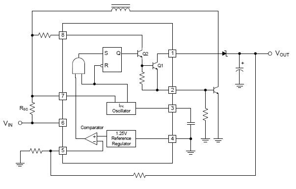
First, that's an archaic chip that requires a lot of circuitry around it to do anything useful. Why use this particular chip? Second, the datasheet gives you an example of how to use this part as a step-up converter with external switch. Why not follow that? Third, blindly following equations in the datasheet is no way to design anything. You have to actually <i>understand</i> what is going on first. Note that the example step-up circuit with external switch uses a NPN transistor as the external switch, not a FET. This switcher chip is more suited to driving a BJT than a FET. Page 8 of the datasheet shows this example circuit:  I see no reason not to follow this, considering you really want to use this chip in the first place. The NPN transistor must be rated for the full output voltage. Since that is apparently 180 V in your case, it should be rated for 200 V at least. Your main question seems to be about R1 in your schematic, which is Rsc in the schematic above. That is the current sensing resistor that the chip uses to shut off the switch when the current gets above the threshold. Once you have picked an inductor, this limit should be set to the saturation limit of the inductor. The external NPN transistor also needs to be rated for this current. Once you know the maximum current you ever want to allow thru the inductor and switch, you look at page 4 of the datasheet. It shows the current limit sense voltage being from 250 to 350 mV. Since 350 mV is the case that results in the highest current, you use that. Rsc is then simply 350 mV divided by the maximum current you want to allow. Again, you need to <i>understand</i> the circuit to pick part values. Once you understand it, how to pick the values will usually be obvious.


