Post History
In some books and other technical papers (also from universities) it is - surprisingly - still claimed that the bipolar transistor (BJT) would be a current-controlled element. And this is true, s...
#13: Post edited
by
 coquelicot
·
2020-10-21T08:34:28Z (over 4 years ago)
coquelicot
·
2020-10-21T08:34:28Z (over 4 years ago)
orth
- > In some books and other technical papers (also from universities) it is - surprisingly - still claimed that the bipolar transistor (BJT) would be a current-controlled element.
- And this is true, subjected to some conditions and approximations.
- >This is simply stated - without any explanation or proof (which I think is impossible).
- On the contrary, this is very possible and follows from an approximation of the Ebers-moll model.
- >For me and also for many students this is an unsatisfactory situation. Therefore, I consider the distinction (current vs. voltage-control) to be very important to avoid contradictions between theory and practice. Because many circuits and observable effects can only be explained with voltage control Ic=f(Vbe).
- Current control is by far the most useful and intuitive representation, that allows to quickly arrive to the understanding of most common circuit topology (e.g. follower). Sure, this model fails to explain everything and fails to be sufficiently precise in some situations. This is where you need the Ebers-Moll equations and the Early effect.
- >But this design procedure cannot be used as a proof for a control of the collector current by the base current.
- Indeed. For a proof, see theoretical expositions, or even Wikipedia, at
- [Bipolar junction transistor](https://en.wikipedia.org/wiki/Bipolar_junction_transistor#Ebers%E2%80%93Moll_model), section "Ebers–Moll model".
- <hr>
- >Interesting thoughts... BTW where can we see the "current control" in the circuit of a follower?
- Let me oversimplify things, by assuming the beta of the transistor is 100, which is a relatively frequent value. So, being current controlled means:
- _Only 1 percent of the emitter current comes from the base, and 99% of the emitter current comes from the collector._
- If the beta is not 100, you use 100/beta percents in place of 1 percent. But thinking with beta = 100 is excellent for the intuition.
- This being said, consider the follower topology:
- 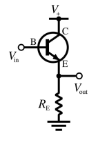
- We know, of course, that the emitter voltage Vout is one diode drop below the base voltage. This does not mean, still, that the emitter voltage "follows" the original signal coming to the base, because the signal in Vin has an output impedance (that is usually high). If the base of the transistor loads too much Vin, then the voltage at the base is lower than the original signal, exactly like if you load too much a 1.5V battery with a 0.1 Ohm resistor (say), then the output voltage is less than 1.5V.
- This is where our rule above comes into play: since the emitter current sinks only 1% of the base current, it is immediately apparent that the signal is loaded 100 times less than if it were loaded directly without the transistor. This is the real point of the follower circuit.
- So, in order for the emitter voltage to follow the signal (one diode drop below), it suffices to make sure the signal can provide 1% of the current sunk by the load, without being degraded.
- Another way to say that is that we want the output impedance of the signal be at most 100 times greater than the load impedance of the transistor. This is often abbreviated as:
- _Be sure the base signal is sufficiently stiff with respect to the maximal emitter current of the transistor._
- If this is not the case, and it is impossible to decrease the output impedance of the signal, just use a transistor with a beta > 100. For example, the beta of a Darlington is often 1000 or larger.
- <hr>
- > show me one single proof that Ib would determine/control Ic
- OK. Here is one:
- From Wikipedia (see link above),
- The unapproximated Ebers-Moll equations used to describe the three currents in any operating region are given below. These equations are based on the transport model for a bipolar junction transistor
- $$
- i_{\text{C}} = I_\text{S} \left[ \left(e^\frac{V_\text{BE}}{V_\text{T}} - e^\frac{V_\text{BC}}{V_\text{T}}\right) - \frac{1}{\beta_\text{R}} \left(e^\frac{V_\text{BC}}{V_\text{T}} - 1\right) \right]
- $$
- $$i_{\text{B}} = I_\text{S} \left[ \frac{1}{\beta_\text{F}} \left(e^\frac{V_\text{BE}}{V_\text{T}} - 1 \right) + \frac{1}{\beta_\text{R}} \left(e^\frac{V_\text{BC}}{V_\text{T}} - 1\right) \right]
- $$
- $$
- i_{\text{E}} = I_\text{S} \left[ \left(e^\frac{V_\text{BE}}{V_\text{T}} - e^\frac{V_\text{BC}}{V_\text{T}}\right) + \frac{1}{\beta_\text{F}} \left(e^\frac{V_\text{BE}}{V_\text{T}} - 1\right) \right]
- $$
- Now, I only consider "normal mode" of operation, that is Vc > Vb > Ve.
- So, Vbc < 0. That means that we can neglect all the terms
- $$e^\frac{V_\text{BC}}{V_\text{T}}$$ in the equations.
- Now, Vbe is at least 0.5V for silicone transistors, and Vt is 26mV at room temperature.
- Hence Vbe/Vt = 19 at least. That means than in the expression of Ib, the huge term exp(Vbe/vt) dominates all the other terms, and we have approximately
- $$I_B = I_S \frac{1}{\beta_F} e^\frac{V_{BE}}{V_T}.$$
- Similarly, we have approximately
- $$I_E = I_S \left(e^\frac{V_{BE}}{V_T} + \frac{1}{\beta_F} e^\frac{V_{BE}}{V_T}\right).$$
- According to Wikipedia again, beta_f is at least equal to 20, so, we can neglect the second term inside the parentheses in the above expression. We get finally
- $$ \frac{I_E}{I_B} = \beta_F,$$
- as desired.
- <hr>
- > I am polite and do not comment on etc.
- Well, yesterday, I felt at some stage like you refuse to admit simple truths and proofs, and simply like useless discussions.
- Waking up this morning, I thought there may, after all, be some additional point to clarify. I update for the last time this answer, then you'll decide if you still want to be only "polite".
- To sum up, you cannot admit (intuitively) that we get rid the exponential form of the "voltage controlled" model, to end up with a simple proportion rule between base and emitter currents.
- Well, the truth is that the exponential "voltage controlled" form has never gone (even at the elementary and approximate level); On the contrary, it is always present and used by EE !
Let me elaborate: we have seen above that, under some wide conditions, and in the normal operation mode, the Ebber-Moll equations are approximately- $$I_B = I_S \frac{1}{\beta_F} e^\frac{V_{BE}}{V_T}, $$
- $$I_C = I_S \ e^\frac{V_{BE}}{V_T}.$$
- This is a system of two equations.
- Dividing the second equation by the first, we get, as above
- $$ I_C = \beta_F I_B. \ \ \ \ \ \ (*)$$
- But that is a single equation; in the original system, there are two equations, and two equations cannot be equivalent to a single equation. So we need another equation to complete equation (*).
- We can pick the second equation in the original system. What does it mean? it means basically that Vbe is equal to one diode drop!!! (I drop the mathematical proof).
- So, finally, the original system is equivalent to the following system:
- $$ I_C = \beta_F I_B,$$
- $$ V_{BE}\ \text{is equal to one diode drop}.$$
- As you see, the "voltage controlled" form has never gone, since the diode drop property is one of the two most basic rules always used together with current control; but IN A FIRST APPROXIMATION, it adopts the trivial form of "diode drop". On the other hand, the "current control" equation is not trivial, although simple. This is why it is usually said the transistor is a current controlled device.
- TO SUM UP: two equations are needed to describe the transistor behavior. The approximate Ebers-Moll are two "voltage controlled" equations, while the "current model" is one "current controlled equation" and one "voltage controlled equation". The two approximate models are equivalent. But the ultra simple form of the current model system explains why it is so widely used.
- > In some books and other technical papers (also from universities) it is - surprisingly - still claimed that the bipolar transistor (BJT) would be a current-controlled element.
- And this is true, subjected to some conditions and approximations.
- >This is simply stated - without any explanation or proof (which I think is impossible).
- On the contrary, this is very possible and follows from an approximation of the Ebers-moll model.
- >For me and also for many students this is an unsatisfactory situation. Therefore, I consider the distinction (current vs. voltage-control) to be very important to avoid contradictions between theory and practice. Because many circuits and observable effects can only be explained with voltage control Ic=f(Vbe).
- Current control is by far the most useful and intuitive representation, that allows to quickly arrive to the understanding of most common circuit topology (e.g. follower). Sure, this model fails to explain everything and fails to be sufficiently precise in some situations. This is where you need the Ebers-Moll equations and the Early effect.
- >But this design procedure cannot be used as a proof for a control of the collector current by the base current.
- Indeed. For a proof, see theoretical expositions, or even Wikipedia, at
- [Bipolar junction transistor](https://en.wikipedia.org/wiki/Bipolar_junction_transistor#Ebers%E2%80%93Moll_model), section "Ebers–Moll model".
- <hr>
- >Interesting thoughts... BTW where can we see the "current control" in the circuit of a follower?
- Let me oversimplify things, by assuming the beta of the transistor is 100, which is a relatively frequent value. So, being current controlled means:
- _Only 1 percent of the emitter current comes from the base, and 99% of the emitter current comes from the collector._
- If the beta is not 100, you use 100/beta percents in place of 1 percent. But thinking with beta = 100 is excellent for the intuition.
- This being said, consider the follower topology:
- 
- We know, of course, that the emitter voltage Vout is one diode drop below the base voltage. This does not mean, still, that the emitter voltage "follows" the original signal coming to the base, because the signal in Vin has an output impedance (that is usually high). If the base of the transistor loads too much Vin, then the voltage at the base is lower than the original signal, exactly like if you load too much a 1.5V battery with a 0.1 Ohm resistor (say), then the output voltage is less than 1.5V.
- This is where our rule above comes into play: since the emitter current sinks only 1% of the base current, it is immediately apparent that the signal is loaded 100 times less than if it were loaded directly without the transistor. This is the real point of the follower circuit.
- So, in order for the emitter voltage to follow the signal (one diode drop below), it suffices to make sure the signal can provide 1% of the current sunk by the load, without being degraded.
- Another way to say that is that we want the output impedance of the signal be at most 100 times greater than the load impedance of the transistor. This is often abbreviated as:
- _Be sure the base signal is sufficiently stiff with respect to the maximal emitter current of the transistor._
- If this is not the case, and it is impossible to decrease the output impedance of the signal, just use a transistor with a beta > 100. For example, the beta of a Darlington is often 1000 or larger.
- <hr>
- > show me one single proof that Ib would determine/control Ic
- OK. Here is one:
- From Wikipedia (see link above),
- The unapproximated Ebers-Moll equations used to describe the three currents in any operating region are given below. These equations are based on the transport model for a bipolar junction transistor
- $$
- i_{\text{C}} = I_\text{S} \left[ \left(e^\frac{V_\text{BE}}{V_\text{T}} - e^\frac{V_\text{BC}}{V_\text{T}}\right) - \frac{1}{\beta_\text{R}} \left(e^\frac{V_\text{BC}}{V_\text{T}} - 1\right) \right]
- $$
- $$i_{\text{B}} = I_\text{S} \left[ \frac{1}{\beta_\text{F}} \left(e^\frac{V_\text{BE}}{V_\text{T}} - 1 \right) + \frac{1}{\beta_\text{R}} \left(e^\frac{V_\text{BC}}{V_\text{T}} - 1\right) \right]
- $$
- $$
- i_{\text{E}} = I_\text{S} \left[ \left(e^\frac{V_\text{BE}}{V_\text{T}} - e^\frac{V_\text{BC}}{V_\text{T}}\right) + \frac{1}{\beta_\text{F}} \left(e^\frac{V_\text{BE}}{V_\text{T}} - 1\right) \right]
- $$
- Now, I only consider "normal mode" of operation, that is Vc > Vb > Ve.
- So, Vbc < 0. That means that we can neglect all the terms
- $$e^\frac{V_\text{BC}}{V_\text{T}}$$ in the equations.
- Now, Vbe is at least 0.5V for silicone transistors, and Vt is 26mV at room temperature.
- Hence Vbe/Vt = 19 at least. That means than in the expression of Ib, the huge term exp(Vbe/vt) dominates all the other terms, and we have approximately
- $$I_B = I_S \frac{1}{\beta_F} e^\frac{V_{BE}}{V_T}.$$
- Similarly, we have approximately
- $$I_E = I_S \left(e^\frac{V_{BE}}{V_T} + \frac{1}{\beta_F} e^\frac{V_{BE}}{V_T}\right).$$
- According to Wikipedia again, beta_f is at least equal to 20, so, we can neglect the second term inside the parentheses in the above expression. We get finally
- $$ \frac{I_E}{I_B} = \beta_F,$$
- as desired.
- <hr>
- > I am polite and do not comment on etc.
- Well, yesterday, I felt at some stage like you refuse to admit simple truths and proofs, and simply like useless discussions.
- Waking up this morning, I thought there may, after all, be some additional point to clarify. I update for the last time this answer, then you'll decide if you still want to be only "polite".
- To sum up, you cannot admit (intuitively) that we get rid the exponential form of the "voltage controlled" model, to end up with a simple proportion rule between base and emitter currents.
- Well, the truth is that the exponential "voltage controlled" form has never gone (even at the elementary and approximate level); On the contrary, it is always present and used by EE !
- Let me elaborate: we have seen above that, under some wide conditions, and in the normal operation mode, the Ebers-Moll equations are approximately
- $$I_B = I_S \frac{1}{\beta_F} e^\frac{V_{BE}}{V_T}, $$
- $$I_C = I_S \ e^\frac{V_{BE}}{V_T}.$$
- This is a system of two equations.
- Dividing the second equation by the first, we get, as above
- $$ I_C = \beta_F I_B. \ \ \ \ \ \ (*)$$
- But that is a single equation; in the original system, there are two equations, and two equations cannot be equivalent to a single equation. So we need another equation to complete equation (*).
- We can pick the second equation in the original system. What does it mean? it means basically that Vbe is equal to one diode drop!!! (I drop the mathematical proof).
- So, finally, the original system is equivalent to the following system:
- $$ I_C = \beta_F I_B,$$
- $$ V_{BE}\ \text{is equal to one diode drop}.$$
- As you see, the "voltage controlled" form has never gone, since the diode drop property is one of the two most basic rules always used together with current control; but IN A FIRST APPROXIMATION, it adopts the trivial form of "diode drop". On the other hand, the "current control" equation is not trivial, although simple. This is why it is usually said the transistor is a current controlled device.
- TO SUM UP: two equations are needed to describe the transistor behavior. The approximate Ebers-Moll are two "voltage controlled" equations, while the "current model" is one "current controlled equation" and one "voltage controlled equation". The two approximate models are equivalent. But the ultra simple form of the current model system explains why it is so widely used.
#12: Post edited
by
coquelicot
·
2020-10-21T08:30:20Z (over 4 years ago)
- > In some books and other technical papers (also from universities) it is - surprisingly - still claimed that the bipolar transistor (BJT) would be a current-controlled element.
- And this is true, subjected to some conditions and approximations.
- >This is simply stated - without any explanation or proof (which I think is impossible).
- On the contrary, this is very possible and follows from an approximation of the Ebers-moll model.
- >For me and also for many students this is an unsatisfactory situation. Therefore, I consider the distinction (current vs. voltage-control) to be very important to avoid contradictions between theory and practice. Because many circuits and observable effects can only be explained with voltage control Ic=f(Vbe).
- Current control is by far the most useful and intuitive representation, that allows to quickly arrive to the understanding of most common circuit topology (e.g. follower). Sure, this model fails to explain everything and fails to be sufficiently precise in some situations. This is where you need the Ebers-Moll equations and the Early effect.
- >But this design procedure cannot be used as a proof for a control of the collector current by the base current.
- Indeed. For a proof, see theoretical expositions, or even Wikipedia, at
- [Bipolar junction transistor](https://en.wikipedia.org/wiki/Bipolar_junction_transistor#Ebers%E2%80%93Moll_model), section "Ebers–Moll model".
- <hr>
- >Interesting thoughts... BTW where can we see the "current control" in the circuit of a follower?
- Let me oversimplify things, by assuming the beta of the transistor is 100, which is a relatively frequent value. So, being current controlled means:
- _Only 1 percent of the emitter current comes from the base, and 99% of the emitter current comes from the collector._
- If the beta is not 100, you use 100/beta percents in place of 1 percent. But thinking with beta = 100 is excellent for the intuition.
- This being said, consider the follower topology:
- 
- We know, of course, that the emitter voltage Vout is one diode drop below the base voltage. This does not mean, still, that the emitter voltage "follows" the original signal coming to the base, because the signal in Vin has an output impedance (that is usually high). If the base of the transistor loads too much Vin, then the voltage at the base is lower than the original signal, exactly like if you load too much a 1.5V battery with a 0.1 Ohm resistor (say), then the output voltage is less than 1.5V.
- This is where our rule above comes into play: since the emitter current sinks only 1% of the base current, it is immediately apparent that the signal is loaded 100 times less than if it were loaded directly without the transistor. This is the real point of the follower circuit.
- So, in order for the emitter voltage to follow the signal (one diode drop below), it suffices to make sure the signal can provide 1% of the current sunk by the load, without being degraded.
- Another way to say that is that we want the output impedance of the signal be at most 100 times greater than the load impedance of the transistor. This is often abbreviated as:
- _Be sure the base signal is sufficiently stiff with respect to the maximal emitter current of the transistor._
- If this is not the case, and it is impossible to decrease the output impedance of the signal, just use a transistor with a beta > 100. For example, the beta of a Darlington is often 1000 or larger.
- <hr>
- > show me one single proof that Ib would determine/control Ic
- OK. Here is one:
- From Wikipedia (see link above),
- The unapproximated Ebers-Moll equations used to describe the three currents in any operating region are given below. These equations are based on the transport model for a bipolar junction transistor
- $$
- i_{\text{C}} = I_\text{S} \left[ \left(e^\frac{V_\text{BE}}{V_\text{T}} - e^\frac{V_\text{BC}}{V_\text{T}}\right) - \frac{1}{\beta_\text{R}} \left(e^\frac{V_\text{BC}}{V_\text{T}} - 1\right) \right]
- $$
- $$i_{\text{B}} = I_\text{S} \left[ \frac{1}{\beta_\text{F}} \left(e^\frac{V_\text{BE}}{V_\text{T}} - 1 \right) + \frac{1}{\beta_\text{R}} \left(e^\frac{V_\text{BC}}{V_\text{T}} - 1\right) \right]
- $$
- $$
- i_{\text{E}} = I_\text{S} \left[ \left(e^\frac{V_\text{BE}}{V_\text{T}} - e^\frac{V_\text{BC}}{V_\text{T}}\right) + \frac{1}{\beta_\text{F}} \left(e^\frac{V_\text{BE}}{V_\text{T}} - 1\right) \right]
- $$
- Now, I only consider "normal mode" of operation, that is Vc > Vb > Ve.
- So, Vbc < 0. That means that we can neglect all the terms
- $$e^\frac{V_\text{BC}}{V_\text{T}}$$ in the equations.
- Now, Vbe is at least 0.5V for silicone transistors, and Vt is 26mV at room temperature.
- Hence Vbe/Vt = 19 at least. That means than in the expression of Ib, the huge term exp(Vbe/vt) dominates all the other terms, and we have approximately
- $$I_B = I_S \frac{1}{\beta_F} e^\frac{V_{BE}}{V_T}.$$
- Similarly, we have approximately
- $$I_E = I_S \left(e^\frac{V_{BE}}{V_T} + \frac{1}{\beta_F} e^\frac{V_{BE}}{V_T}\right).$$
- According to Wikipedia again, beta_f is at least equal to 20, so, we can neglect the second term inside the parentheses in the above expression. We get finally
- $$ \frac{I_E}{I_B} = \beta_F,$$
- as desired.
- <hr>
- > I am polite and do not comment on etc.
- Well, yesterday, I felt at some stage like you refuse to admit simple truths and proofs, and simply like useless discussions.
- Waking up this morning, I thought there may, after all, be some additional point to clarify. I update for the last time this answer, then you'll decide if you still want to be only "polite".
- To sum up, you cannot admit (intuitively) that we get rid the exponential form of the "voltage controlled" model, to end up with a simple proportion rule between base and emitter currents.
- Well, the truth is that the exponential "voltage controlled" form has never gone (even at the elementary and approximate level); On the contrary, it is always present and used by EE !
- Let me elaborate: we have seen above that, under some wide conditions, and in the normal operation mode, the Ebber-Moll equations are approximately
- $$I_B = I_S \frac{1}{\beta_F} e^\frac{V_{BE}}{V_T}, $$
- $$I_C = I_S \ e^\frac{V_{BE}}{V_T}.$$
- This is a system of two equations.
- Dividing the second equation by the first, we get, as above
- $$ I_C = \beta_F I_B. \ \ \ \ \ \ (*)$$
- But that is a single equation; in the original system, there are two equations, and two equations cannot be equivalent to a single equation. So we need another equation to complete equation (*).
- We can pick the second equation in the original system. What does it mean? it means basically that Vbe is equal to one diode drop!!! (I drop the mathematical proof).
- So, finally, the original system is equivalent to the following system:
- $$ I_C = \beta_F I_B,$$
- $$ V_{BE}\ \text{is equal to one diode drop}.$$
- As you see, the "voltage controlled" form has never gone, since the diode drop property is one of the two most basic rules always used together with current control; but IN A FIRST APPROXIMATION, it adopts the trivial form of "diode drop". On the other hand, the "current control" equation is not trivial, although simple. This is why it is usually said the transistor is a current controlled device.
TO SUM UP: two equations are needed to describe the transistor behavior. The approximate Ebers-Moll are two "voltage controlled" equations, while the "current model" is one "current controlled equation" and one "voltage controlled equation". The two approximate models are equivalent. but the ultra simple form of the current model system explain why it is so widely used.
- > In some books and other technical papers (also from universities) it is - surprisingly - still claimed that the bipolar transistor (BJT) would be a current-controlled element.
- And this is true, subjected to some conditions and approximations.
- >This is simply stated - without any explanation or proof (which I think is impossible).
- On the contrary, this is very possible and follows from an approximation of the Ebers-moll model.
- >For me and also for many students this is an unsatisfactory situation. Therefore, I consider the distinction (current vs. voltage-control) to be very important to avoid contradictions between theory and practice. Because many circuits and observable effects can only be explained with voltage control Ic=f(Vbe).
- Current control is by far the most useful and intuitive representation, that allows to quickly arrive to the understanding of most common circuit topology (e.g. follower). Sure, this model fails to explain everything and fails to be sufficiently precise in some situations. This is where you need the Ebers-Moll equations and the Early effect.
- >But this design procedure cannot be used as a proof for a control of the collector current by the base current.
- Indeed. For a proof, see theoretical expositions, or even Wikipedia, at
- [Bipolar junction transistor](https://en.wikipedia.org/wiki/Bipolar_junction_transistor#Ebers%E2%80%93Moll_model), section "Ebers–Moll model".
- <hr>
- >Interesting thoughts... BTW where can we see the "current control" in the circuit of a follower?
- Let me oversimplify things, by assuming the beta of the transistor is 100, which is a relatively frequent value. So, being current controlled means:
- _Only 1 percent of the emitter current comes from the base, and 99% of the emitter current comes from the collector._
- If the beta is not 100, you use 100/beta percents in place of 1 percent. But thinking with beta = 100 is excellent for the intuition.
- This being said, consider the follower topology:
- 
- We know, of course, that the emitter voltage Vout is one diode drop below the base voltage. This does not mean, still, that the emitter voltage "follows" the original signal coming to the base, because the signal in Vin has an output impedance (that is usually high). If the base of the transistor loads too much Vin, then the voltage at the base is lower than the original signal, exactly like if you load too much a 1.5V battery with a 0.1 Ohm resistor (say), then the output voltage is less than 1.5V.
- This is where our rule above comes into play: since the emitter current sinks only 1% of the base current, it is immediately apparent that the signal is loaded 100 times less than if it were loaded directly without the transistor. This is the real point of the follower circuit.
- So, in order for the emitter voltage to follow the signal (one diode drop below), it suffices to make sure the signal can provide 1% of the current sunk by the load, without being degraded.
- Another way to say that is that we want the output impedance of the signal be at most 100 times greater than the load impedance of the transistor. This is often abbreviated as:
- _Be sure the base signal is sufficiently stiff with respect to the maximal emitter current of the transistor._
- If this is not the case, and it is impossible to decrease the output impedance of the signal, just use a transistor with a beta > 100. For example, the beta of a Darlington is often 1000 or larger.
- <hr>
- > show me one single proof that Ib would determine/control Ic
- OK. Here is one:
- From Wikipedia (see link above),
- The unapproximated Ebers-Moll equations used to describe the three currents in any operating region are given below. These equations are based on the transport model for a bipolar junction transistor
- $$
- i_{\text{C}} = I_\text{S} \left[ \left(e^\frac{V_\text{BE}}{V_\text{T}} - e^\frac{V_\text{BC}}{V_\text{T}}\right) - \frac{1}{\beta_\text{R}} \left(e^\frac{V_\text{BC}}{V_\text{T}} - 1\right) \right]
- $$
- $$i_{\text{B}} = I_\text{S} \left[ \frac{1}{\beta_\text{F}} \left(e^\frac{V_\text{BE}}{V_\text{T}} - 1 \right) + \frac{1}{\beta_\text{R}} \left(e^\frac{V_\text{BC}}{V_\text{T}} - 1\right) \right]
- $$
- $$
- i_{\text{E}} = I_\text{S} \left[ \left(e^\frac{V_\text{BE}}{V_\text{T}} - e^\frac{V_\text{BC}}{V_\text{T}}\right) + \frac{1}{\beta_\text{F}} \left(e^\frac{V_\text{BE}}{V_\text{T}} - 1\right) \right]
- $$
- Now, I only consider "normal mode" of operation, that is Vc > Vb > Ve.
- So, Vbc < 0. That means that we can neglect all the terms
- $$e^\frac{V_\text{BC}}{V_\text{T}}$$ in the equations.
- Now, Vbe is at least 0.5V for silicone transistors, and Vt is 26mV at room temperature.
- Hence Vbe/Vt = 19 at least. That means than in the expression of Ib, the huge term exp(Vbe/vt) dominates all the other terms, and we have approximately
- $$I_B = I_S \frac{1}{\beta_F} e^\frac{V_{BE}}{V_T}.$$
- Similarly, we have approximately
- $$I_E = I_S \left(e^\frac{V_{BE}}{V_T} + \frac{1}{\beta_F} e^\frac{V_{BE}}{V_T}\right).$$
- According to Wikipedia again, beta_f is at least equal to 20, so, we can neglect the second term inside the parentheses in the above expression. We get finally
- $$ \frac{I_E}{I_B} = \beta_F,$$
- as desired.
- <hr>
- > I am polite and do not comment on etc.
- Well, yesterday, I felt at some stage like you refuse to admit simple truths and proofs, and simply like useless discussions.
- Waking up this morning, I thought there may, after all, be some additional point to clarify. I update for the last time this answer, then you'll decide if you still want to be only "polite".
- To sum up, you cannot admit (intuitively) that we get rid the exponential form of the "voltage controlled" model, to end up with a simple proportion rule between base and emitter currents.
- Well, the truth is that the exponential "voltage controlled" form has never gone (even at the elementary and approximate level); On the contrary, it is always present and used by EE !
- Let me elaborate: we have seen above that, under some wide conditions, and in the normal operation mode, the Ebber-Moll equations are approximately
- $$I_B = I_S \frac{1}{\beta_F} e^\frac{V_{BE}}{V_T}, $$
- $$I_C = I_S \ e^\frac{V_{BE}}{V_T}.$$
- This is a system of two equations.
- Dividing the second equation by the first, we get, as above
- $$ I_C = \beta_F I_B. \ \ \ \ \ \ (*)$$
- But that is a single equation; in the original system, there are two equations, and two equations cannot be equivalent to a single equation. So we need another equation to complete equation (*).
- We can pick the second equation in the original system. What does it mean? it means basically that Vbe is equal to one diode drop!!! (I drop the mathematical proof).
- So, finally, the original system is equivalent to the following system:
- $$ I_C = \beta_F I_B,$$
- $$ V_{BE}\ \text{is equal to one diode drop}.$$
- As you see, the "voltage controlled" form has never gone, since the diode drop property is one of the two most basic rules always used together with current control; but IN A FIRST APPROXIMATION, it adopts the trivial form of "diode drop". On the other hand, the "current control" equation is not trivial, although simple. This is why it is usually said the transistor is a current controlled device.
- TO SUM UP: two equations are needed to describe the transistor behavior. The approximate Ebers-Moll are two "voltage controlled" equations, while the "current model" is one "current controlled equation" and one "voltage controlled equation". The two approximate models are equivalent. But the ultra simple form of the current model system explains why it is so widely used.
#11: Post edited
by
coquelicot
·
2020-10-21T08:09:16Z (over 4 years ago)
- > In some books and other technical papers (also from universities) it is - surprisingly - still claimed that the bipolar transistor (BJT) would be a current-controlled element.
- And this is true, subjected to some conditions and approximations.
- >This is simply stated - without any explanation or proof (which I think is impossible).
- On the contrary, this is very possible and follows from an approximation of the Ebers-moll model.
- >For me and also for many students this is an unsatisfactory situation. Therefore, I consider the distinction (current vs. voltage-control) to be very important to avoid contradictions between theory and practice. Because many circuits and observable effects can only be explained with voltage control Ic=f(Vbe).
- Current control is by far the most useful and intuitive representation, that allows to quickly arrive to the understanding of most common circuit topology (e.g. follower). Sure, this model fails to explain everything and fails to be sufficiently precise in some situations. This is where you need the Ebers-Moll equations and the Early effect.
- >But this design procedure cannot be used as a proof for a control of the collector current by the base current.
- Indeed. For a proof, see theoretical expositions, or even Wikipedia, at
- [Bipolar junction transistor](https://en.wikipedia.org/wiki/Bipolar_junction_transistor#Ebers%E2%80%93Moll_model), section "Ebers–Moll model".
- <hr>
- >Interesting thoughts... BTW where can we see the "current control" in the circuit of a follower?
- Let me oversimplify things, by assuming the beta of the transistor is 100, which is a relatively frequent value. So, being current controlled means:
- _Only 1 percent of the emitter current comes from the base, and 99% of the emitter current comes from the collector._
- If the beta is not 100, you use 100/beta percents in place of 1 percent. But thinking with beta = 100 is excellent for the intuition.
- This being said, consider the follower topology:
- 
- We know, of course, that the emitter voltage Vout is one diode drop below the base voltage. This does not mean, still, that the emitter voltage "follows" the original signal coming to the base, because the signal in Vin has an output impedance (that is usually high). If the base of the transistor loads too much Vin, then the voltage at the base is lower than the original signal, exactly like if you load too much a 1.5V battery with a 0.1 Ohm resistor (say), then the output voltage is less than 1.5V.
- This is where our rule above comes into play: since the emitter current sinks only 1% of the base current, it is immediately apparent that the signal is loaded 100 times less than if it were loaded directly without the transistor. This is the real point of the follower circuit.
- So, in order for the emitter voltage to follow the signal (one diode drop below), it suffices to make sure the signal can provide 1% of the current sunk by the load, without being degraded.
- Another way to say that is that we want the output impedance of the signal be at most 100 times greater than the load impedance of the transistor. This is often abbreviated as:
- _Be sure the base signal is sufficiently stiff with respect to the maximal emitter current of the transistor._
- If this is not the case, and it is impossible to decrease the output impedance of the signal, just use a transistor with a beta > 100. For example, the beta of a Darlington is often 1000 or larger.
- <hr>
- > show me one single proof that Ib would determine/control Ic
- OK. Here is one:
- From Wikipedia (see link above),
- The unapproximated Ebers-Moll equations used to describe the three currents in any operating region are given below. These equations are based on the transport model for a bipolar junction transistor
- $$
- i_{\text{C}} = I_\text{S} \left[ \left(e^\frac{V_\text{BE}}{V_\text{T}} - e^\frac{V_\text{BC}}{V_\text{T}}\right) - \frac{1}{\beta_\text{R}} \left(e^\frac{V_\text{BC}}{V_\text{T}} - 1\right) \right]
- $$
- $$i_{\text{B}} = I_\text{S} \left[ \frac{1}{\beta_\text{F}} \left(e^\frac{V_\text{BE}}{V_\text{T}} - 1 \right) + \frac{1}{\beta_\text{R}} \left(e^\frac{V_\text{BC}}{V_\text{T}} - 1\right) \right]
- $$
- $$
- i_{\text{E}} = I_\text{S} \left[ \left(e^\frac{V_\text{BE}}{V_\text{T}} - e^\frac{V_\text{BC}}{V_\text{T}}\right) + \frac{1}{\beta_\text{F}} \left(e^\frac{V_\text{BE}}{V_\text{T}} - 1\right) \right]
- $$
- Now, I only consider "normal mode" of operation, that is Vc > Vb > Ve.
- So, Vbc < 0. That means that we can neglect all the terms
- $$e^\frac{V_\text{BC}}{V_\text{T}}$$ in the equations.
- Now, Vbe is at least 0.5V for silicone transistors, and Vt is 26mV at room temperature.
- Hence Vbe/Vt = 19 at least. That means than in the expression of Ib, the huge term exp(Vbe/vt) dominates all the other terms, and we have approximately
- $$I_B = I_S \frac{1}{\beta_F} e^\frac{V_{BE}}{V_T}.$$
- Similarly, we have approximately
- $$I_E = I_S \left(e^\frac{V_{BE}}{V_T} + \frac{1}{\beta_F} e^\frac{V_{BE}}{V_T}\right).$$
- According to Wikipedia again, beta_f is at least equal to 20, so, we can neglect the second term inside the parentheses in the above expression. We get finally
- $$ \frac{I_E}{I_B} = \beta_F,$$
- as desired.
- <hr>
- > I am polite and do not comment on etc.
- Well, yesterday, I felt at some stage like you refuse to admit simple truths and proofs, and simply like useless discussions.
- Waking up this morning, I thought there may, after all, be some additional point to clarify. I update for the last time this answer, then you'll decide if you still want to be only "polite".
- To sum up, you cannot admit (intuitively) that we get rid the exponential form of the "voltage controlled" model, to end up with a simple proportion rule between base and emitter currents.
- Well, the truth is that the exponential "voltage controlled" form has never gone (even at the elementary and approximate level); On the contrary, it is always present and used by EE !
- Let me elaborate: we have seen above that, under some wide conditions, and in the normal operation mode, the Ebber-Moll equations are approximately
- $$I_B = I_S \frac{1}{\beta_F} e^\frac{V_{BE}}{V_T}, $$
- $$I_C = I_S \ e^\frac{V_{BE}}{V_T}.$$
- This is a system of two equations.
- Dividing the second equation by the first, we get, as above
- $$ I_C = \beta_F I_B. \ \ \ \ \ \ (*)$$
- But that is a single equation; in the original system, there are two equations, and two equations cannot be equivalent to a single equation. So we need another equation to complete equation (*).
- We can pick the second equation in the original system. What does it mean? it means basically that Vbe is equal to one diode drop!!! (I drop the mathematical proof).
- So, finally, the original system is equivalent to the following system:
- $$ I_C = \beta_F I_B,$$
- $$ V_{BE}\ \text{is equal to one diode drop}.$$
- As you see, the "voltage controlled" form has never gone, since the diode drop property is one of the two most basic rules always used together with current control; but IN A FIRST APPROXIMATION, it adopts the trivial form of "diode drop". On the other hand, the "current control" equation is not trivial, although simple. This is why it is usually said the transistor is a current controlled device.
TO SUM UP: two equations are needed to describe the transistor behavior. The approximate Ebers-Moll are two "voltage controlled" equations, while the "current model" is one "current controlled equation" and one "voltage controlled equation". The two approximate models are equivalent.
- > In some books and other technical papers (also from universities) it is - surprisingly - still claimed that the bipolar transistor (BJT) would be a current-controlled element.
- And this is true, subjected to some conditions and approximations.
- >This is simply stated - without any explanation or proof (which I think is impossible).
- On the contrary, this is very possible and follows from an approximation of the Ebers-moll model.
- >For me and also for many students this is an unsatisfactory situation. Therefore, I consider the distinction (current vs. voltage-control) to be very important to avoid contradictions between theory and practice. Because many circuits and observable effects can only be explained with voltage control Ic=f(Vbe).
- Current control is by far the most useful and intuitive representation, that allows to quickly arrive to the understanding of most common circuit topology (e.g. follower). Sure, this model fails to explain everything and fails to be sufficiently precise in some situations. This is where you need the Ebers-Moll equations and the Early effect.
- >But this design procedure cannot be used as a proof for a control of the collector current by the base current.
- Indeed. For a proof, see theoretical expositions, or even Wikipedia, at
- [Bipolar junction transistor](https://en.wikipedia.org/wiki/Bipolar_junction_transistor#Ebers%E2%80%93Moll_model), section "Ebers–Moll model".
- <hr>
- >Interesting thoughts... BTW where can we see the "current control" in the circuit of a follower?
- Let me oversimplify things, by assuming the beta of the transistor is 100, which is a relatively frequent value. So, being current controlled means:
- _Only 1 percent of the emitter current comes from the base, and 99% of the emitter current comes from the collector._
- If the beta is not 100, you use 100/beta percents in place of 1 percent. But thinking with beta = 100 is excellent for the intuition.
- This being said, consider the follower topology:
- 
- We know, of course, that the emitter voltage Vout is one diode drop below the base voltage. This does not mean, still, that the emitter voltage "follows" the original signal coming to the base, because the signal in Vin has an output impedance (that is usually high). If the base of the transistor loads too much Vin, then the voltage at the base is lower than the original signal, exactly like if you load too much a 1.5V battery with a 0.1 Ohm resistor (say), then the output voltage is less than 1.5V.
- This is where our rule above comes into play: since the emitter current sinks only 1% of the base current, it is immediately apparent that the signal is loaded 100 times less than if it were loaded directly without the transistor. This is the real point of the follower circuit.
- So, in order for the emitter voltage to follow the signal (one diode drop below), it suffices to make sure the signal can provide 1% of the current sunk by the load, without being degraded.
- Another way to say that is that we want the output impedance of the signal be at most 100 times greater than the load impedance of the transistor. This is often abbreviated as:
- _Be sure the base signal is sufficiently stiff with respect to the maximal emitter current of the transistor._
- If this is not the case, and it is impossible to decrease the output impedance of the signal, just use a transistor with a beta > 100. For example, the beta of a Darlington is often 1000 or larger.
- <hr>
- > show me one single proof that Ib would determine/control Ic
- OK. Here is one:
- From Wikipedia (see link above),
- The unapproximated Ebers-Moll equations used to describe the three currents in any operating region are given below. These equations are based on the transport model for a bipolar junction transistor
- $$
- i_{\text{C}} = I_\text{S} \left[ \left(e^\frac{V_\text{BE}}{V_\text{T}} - e^\frac{V_\text{BC}}{V_\text{T}}\right) - \frac{1}{\beta_\text{R}} \left(e^\frac{V_\text{BC}}{V_\text{T}} - 1\right) \right]
- $$
- $$i_{\text{B}} = I_\text{S} \left[ \frac{1}{\beta_\text{F}} \left(e^\frac{V_\text{BE}}{V_\text{T}} - 1 \right) + \frac{1}{\beta_\text{R}} \left(e^\frac{V_\text{BC}}{V_\text{T}} - 1\right) \right]
- $$
- $$
- i_{\text{E}} = I_\text{S} \left[ \left(e^\frac{V_\text{BE}}{V_\text{T}} - e^\frac{V_\text{BC}}{V_\text{T}}\right) + \frac{1}{\beta_\text{F}} \left(e^\frac{V_\text{BE}}{V_\text{T}} - 1\right) \right]
- $$
- Now, I only consider "normal mode" of operation, that is Vc > Vb > Ve.
- So, Vbc < 0. That means that we can neglect all the terms
- $$e^\frac{V_\text{BC}}{V_\text{T}}$$ in the equations.
- Now, Vbe is at least 0.5V for silicone transistors, and Vt is 26mV at room temperature.
- Hence Vbe/Vt = 19 at least. That means than in the expression of Ib, the huge term exp(Vbe/vt) dominates all the other terms, and we have approximately
- $$I_B = I_S \frac{1}{\beta_F} e^\frac{V_{BE}}{V_T}.$$
- Similarly, we have approximately
- $$I_E = I_S \left(e^\frac{V_{BE}}{V_T} + \frac{1}{\beta_F} e^\frac{V_{BE}}{V_T}\right).$$
- According to Wikipedia again, beta_f is at least equal to 20, so, we can neglect the second term inside the parentheses in the above expression. We get finally
- $$ \frac{I_E}{I_B} = \beta_F,$$
- as desired.
- <hr>
- > I am polite and do not comment on etc.
- Well, yesterday, I felt at some stage like you refuse to admit simple truths and proofs, and simply like useless discussions.
- Waking up this morning, I thought there may, after all, be some additional point to clarify. I update for the last time this answer, then you'll decide if you still want to be only "polite".
- To sum up, you cannot admit (intuitively) that we get rid the exponential form of the "voltage controlled" model, to end up with a simple proportion rule between base and emitter currents.
- Well, the truth is that the exponential "voltage controlled" form has never gone (even at the elementary and approximate level); On the contrary, it is always present and used by EE !
- Let me elaborate: we have seen above that, under some wide conditions, and in the normal operation mode, the Ebber-Moll equations are approximately
- $$I_B = I_S \frac{1}{\beta_F} e^\frac{V_{BE}}{V_T}, $$
- $$I_C = I_S \ e^\frac{V_{BE}}{V_T}.$$
- This is a system of two equations.
- Dividing the second equation by the first, we get, as above
- $$ I_C = \beta_F I_B. \ \ \ \ \ \ (*)$$
- But that is a single equation; in the original system, there are two equations, and two equations cannot be equivalent to a single equation. So we need another equation to complete equation (*).
- We can pick the second equation in the original system. What does it mean? it means basically that Vbe is equal to one diode drop!!! (I drop the mathematical proof).
- So, finally, the original system is equivalent to the following system:
- $$ I_C = \beta_F I_B,$$
- $$ V_{BE}\ \text{is equal to one diode drop}.$$
- As you see, the "voltage controlled" form has never gone, since the diode drop property is one of the two most basic rules always used together with current control; but IN A FIRST APPROXIMATION, it adopts the trivial form of "diode drop". On the other hand, the "current control" equation is not trivial, although simple. This is why it is usually said the transistor is a current controlled device.
- TO SUM UP: two equations are needed to describe the transistor behavior. The approximate Ebers-Moll are two "voltage controlled" equations, while the "current model" is one "current controlled equation" and one "voltage controlled equation". The two approximate models are equivalent. but the ultra simple form of the current model system explain why it is so widely used.
#10: Post edited
by
coquelicot
·
2020-10-21T08:00:42Z (over 4 years ago)
- > In some books and other technical papers (also from universities) it is - surprisingly - still claimed that the bipolar transistor (BJT) would be a current-controlled element.
- And this is true, subjected to some conditions and approximations.
- >This is simply stated - without any explanation or proof (which I think is impossible).
- On the contrary, this is very possible and follows from an approximation of the Ebers-moll model.
- >For me and also for many students this is an unsatisfactory situation. Therefore, I consider the distinction (current vs. voltage-control) to be very important to avoid contradictions between theory and practice. Because many circuits and observable effects can only be explained with voltage control Ic=f(Vbe).
- Current control is by far the most useful and intuitive representation, that allows to quickly arrive to the understanding of most common circuit topology (e.g. follower). Sure, this model fails to explain everything and fails to be sufficiently precise in some situations. This is where you need the Ebers-Moll equations and the Early effect.
- >But this design procedure cannot be used as a proof for a control of the collector current by the base current.
- Indeed. For a proof, see theoretical expositions, or even Wikipedia, at
- [Bipolar junction transistor](https://en.wikipedia.org/wiki/Bipolar_junction_transistor#Ebers%E2%80%93Moll_model), section "Ebers–Moll model".
- <hr>
- >Interesting thoughts... BTW where can we see the "current control" in the circuit of a follower?
- Let me oversimplify things, by assuming the beta of the transistor is 100, which is a relatively frequent value. So, being current controlled means:
- _Only 1 percent of the emitter current comes from the base, and 99% of the emitter current comes from the collector._
- If the beta is not 100, you use 100/beta percents in place of 1 percent. But thinking with beta = 100 is excellent for the intuition.
- This being said, consider the follower topology:
- 
- We know, of course, that the emitter voltage Vout is one diode drop below the base voltage. This does not mean, still, that the emitter voltage "follows" the original signal coming to the base, because the signal in Vin has an output impedance (that is usually high). If the base of the transistor loads too much Vin, then the voltage at the base is lower than the original signal, exactly like if you load too much a 1.5V battery with a 0.1 Ohm resistor (say), then the output voltage is less than 1.5V.
- This is where our rule above comes into play: since the emitter current sinks only 1% of the base current, it is immediately apparent that the signal is loaded 100 times less than if it were loaded directly without the transistor. This is the real point of the follower circuit.
- So, in order for the emitter voltage to follow the signal (one diode drop below), it suffices to make sure the signal can provide 1% of the current sunk by the load, without being degraded.
- Another way to say that is that we want the output impedance of the signal be at most 100 times greater than the load impedance of the transistor. This is often abbreviated as:
- _Be sure the base signal is sufficiently stiff with respect to the maximal emitter current of the transistor._
- If this is not the case, and it is impossible to decrease the output impedance of the signal, just use a transistor with a beta > 100. For example, the beta of a Darlington is often 1000 or larger.
- <hr>
- > show me one single proof that Ib would determine/control Ic
- OK. Here is one:
- From Wikipedia (see link above),
- The unapproximated Ebers-Moll equations used to describe the three currents in any operating region are given below. These equations are based on the transport model for a bipolar junction transistor
- $$
- i_{\text{C}} = I_\text{S} \left[ \left(e^\frac{V_\text{BE}}{V_\text{T}} - e^\frac{V_\text{BC}}{V_\text{T}}\right) - \frac{1}{\beta_\text{R}} \left(e^\frac{V_\text{BC}}{V_\text{T}} - 1\right) \right]
- $$
- $$i_{\text{B}} = I_\text{S} \left[ \frac{1}{\beta_\text{F}} \left(e^\frac{V_\text{BE}}{V_\text{T}} - 1 \right) + \frac{1}{\beta_\text{R}} \left(e^\frac{V_\text{BC}}{V_\text{T}} - 1\right) \right]
- $$
- $$
- i_{\text{E}} = I_\text{S} \left[ \left(e^\frac{V_\text{BE}}{V_\text{T}} - e^\frac{V_\text{BC}}{V_\text{T}}\right) + \frac{1}{\beta_\text{F}} \left(e^\frac{V_\text{BE}}{V_\text{T}} - 1\right) \right]
- $$
- Now, I only consider "normal mode" of operation, that is Vc > Vb > Ve.
- So, Vbc < 0. That means that we can neglect all the terms
- $$e^\frac{V_\text{BC}}{V_\text{T}}$$ in the equations.
- Now, Vbe is at least 0.5V for silicone transistors, and Vt is 26mV at room temperature.
- Hence Vbe/Vt = 19 at least. That means than in the expression of Ib, the huge term exp(Vbe/vt) dominates all the other terms, and we have approximately
- $$I_B = I_S \frac{1}{\beta_F} e^\frac{V_{BE}}{V_T}.$$
- Similarly, we have approximately
- $$I_E = I_S \left(e^\frac{V_{BE}}{V_T} + \frac{1}{\beta_F} e^\frac{V_{BE}}{V_T}\right).$$
- According to Wikipedia again, beta_f is at least equal to 20, so, we can neglect the second term inside the parentheses in the above expression. We get finally
- $$ \frac{I_E}{I_B} = \beta_F,$$
- as desired.
- <hr>
- > I am polite and do not comment on etc.
- Well, yesterday, I felt at some stage like you refuse to admit simple truths and proofs, and simply like useless discussions.
- Waking up this morning, I thought there may, after all, be some additional point to clarify. I update for the last time this answer, then you'll decide if you still want to be only "polite".
- To sum up, you cannot admit (intuitively) that we get rid the exponential form of the "voltage controlled" model, to end up with a simple proportion rule between base and emitter currents.
- Well, the truth is that the exponential "voltage controlled" form has never gone (even at the elementary and approximate level); On the contrary, it is always present and used by EE !
- Let me elaborate: we have seen above that, under some wide conditions, and in the normal operation mode, the Ebber-Moll equations are approximately
- $$I_B = I_S \frac{1}{\beta_F} e^\frac{V_{BE}}{V_T}, $$
- $$I_C = I_S \ e^\frac{V_{BE}}{V_T}.$$
- This is a system of two equations.
- Dividing the second equation by the first, we get, as above
- $$ I_C = \beta_F I_B. \ \ \ \ \ \ (*)$$
- But that is a single equation; in the original system, there are two equations, and two equations cannot be equivalent to a single equation. So we need another equation to complete equation (*).
- We can pick the second equation in the original system. What does it mean? it means basically that Vbe is equal to one diode drop!!! (I drop the mathematical proof).
- So, finally, the original system is equivalent to the following system:
- $$ I_C = \beta_F I_B,$$
- $$ V_{BE}\ \text{is equal to one diode drop}.$$
- As you see, the "voltage controlled" form has never gone, since the diode drop property is one of the two most basic rules always used together with current control; but IN A FIRST APPROXIMATION, it adopts the trivial form of "diode drop". On the other hand, the "current control" equation is not trivial, although simple. This is why it is usually said the transistor is a current controlled device.
TO SUM UP: two equations are needed to describe the transistor behavior. The approximate Ebber-Moll are two "voltage controlled" equations, while the "current model" is one "current controlled equation" and one "voltage controlled equation". The two approximate models are equivalent.
- > In some books and other technical papers (also from universities) it is - surprisingly - still claimed that the bipolar transistor (BJT) would be a current-controlled element.
- And this is true, subjected to some conditions and approximations.
- >This is simply stated - without any explanation or proof (which I think is impossible).
- On the contrary, this is very possible and follows from an approximation of the Ebers-moll model.
- >For me and also for many students this is an unsatisfactory situation. Therefore, I consider the distinction (current vs. voltage-control) to be very important to avoid contradictions between theory and practice. Because many circuits and observable effects can only be explained with voltage control Ic=f(Vbe).
- Current control is by far the most useful and intuitive representation, that allows to quickly arrive to the understanding of most common circuit topology (e.g. follower). Sure, this model fails to explain everything and fails to be sufficiently precise in some situations. This is where you need the Ebers-Moll equations and the Early effect.
- >But this design procedure cannot be used as a proof for a control of the collector current by the base current.
- Indeed. For a proof, see theoretical expositions, or even Wikipedia, at
- [Bipolar junction transistor](https://en.wikipedia.org/wiki/Bipolar_junction_transistor#Ebers%E2%80%93Moll_model), section "Ebers–Moll model".
- <hr>
- >Interesting thoughts... BTW where can we see the "current control" in the circuit of a follower?
- Let me oversimplify things, by assuming the beta of the transistor is 100, which is a relatively frequent value. So, being current controlled means:
- _Only 1 percent of the emitter current comes from the base, and 99% of the emitter current comes from the collector._
- If the beta is not 100, you use 100/beta percents in place of 1 percent. But thinking with beta = 100 is excellent for the intuition.
- This being said, consider the follower topology:
- 
- We know, of course, that the emitter voltage Vout is one diode drop below the base voltage. This does not mean, still, that the emitter voltage "follows" the original signal coming to the base, because the signal in Vin has an output impedance (that is usually high). If the base of the transistor loads too much Vin, then the voltage at the base is lower than the original signal, exactly like if you load too much a 1.5V battery with a 0.1 Ohm resistor (say), then the output voltage is less than 1.5V.
- This is where our rule above comes into play: since the emitter current sinks only 1% of the base current, it is immediately apparent that the signal is loaded 100 times less than if it were loaded directly without the transistor. This is the real point of the follower circuit.
- So, in order for the emitter voltage to follow the signal (one diode drop below), it suffices to make sure the signal can provide 1% of the current sunk by the load, without being degraded.
- Another way to say that is that we want the output impedance of the signal be at most 100 times greater than the load impedance of the transistor. This is often abbreviated as:
- _Be sure the base signal is sufficiently stiff with respect to the maximal emitter current of the transistor._
- If this is not the case, and it is impossible to decrease the output impedance of the signal, just use a transistor with a beta > 100. For example, the beta of a Darlington is often 1000 or larger.
- <hr>
- > show me one single proof that Ib would determine/control Ic
- OK. Here is one:
- From Wikipedia (see link above),
- The unapproximated Ebers-Moll equations used to describe the three currents in any operating region are given below. These equations are based on the transport model for a bipolar junction transistor
- $$
- i_{\text{C}} = I_\text{S} \left[ \left(e^\frac{V_\text{BE}}{V_\text{T}} - e^\frac{V_\text{BC}}{V_\text{T}}\right) - \frac{1}{\beta_\text{R}} \left(e^\frac{V_\text{BC}}{V_\text{T}} - 1\right) \right]
- $$
- $$i_{\text{B}} = I_\text{S} \left[ \frac{1}{\beta_\text{F}} \left(e^\frac{V_\text{BE}}{V_\text{T}} - 1 \right) + \frac{1}{\beta_\text{R}} \left(e^\frac{V_\text{BC}}{V_\text{T}} - 1\right) \right]
- $$
- $$
- i_{\text{E}} = I_\text{S} \left[ \left(e^\frac{V_\text{BE}}{V_\text{T}} - e^\frac{V_\text{BC}}{V_\text{T}}\right) + \frac{1}{\beta_\text{F}} \left(e^\frac{V_\text{BE}}{V_\text{T}} - 1\right) \right]
- $$
- Now, I only consider "normal mode" of operation, that is Vc > Vb > Ve.
- So, Vbc < 0. That means that we can neglect all the terms
- $$e^\frac{V_\text{BC}}{V_\text{T}}$$ in the equations.
- Now, Vbe is at least 0.5V for silicone transistors, and Vt is 26mV at room temperature.
- Hence Vbe/Vt = 19 at least. That means than in the expression of Ib, the huge term exp(Vbe/vt) dominates all the other terms, and we have approximately
- $$I_B = I_S \frac{1}{\beta_F} e^\frac{V_{BE}}{V_T}.$$
- Similarly, we have approximately
- $$I_E = I_S \left(e^\frac{V_{BE}}{V_T} + \frac{1}{\beta_F} e^\frac{V_{BE}}{V_T}\right).$$
- According to Wikipedia again, beta_f is at least equal to 20, so, we can neglect the second term inside the parentheses in the above expression. We get finally
- $$ \frac{I_E}{I_B} = \beta_F,$$
- as desired.
- <hr>
- > I am polite and do not comment on etc.
- Well, yesterday, I felt at some stage like you refuse to admit simple truths and proofs, and simply like useless discussions.
- Waking up this morning, I thought there may, after all, be some additional point to clarify. I update for the last time this answer, then you'll decide if you still want to be only "polite".
- To sum up, you cannot admit (intuitively) that we get rid the exponential form of the "voltage controlled" model, to end up with a simple proportion rule between base and emitter currents.
- Well, the truth is that the exponential "voltage controlled" form has never gone (even at the elementary and approximate level); On the contrary, it is always present and used by EE !
- Let me elaborate: we have seen above that, under some wide conditions, and in the normal operation mode, the Ebber-Moll equations are approximately
- $$I_B = I_S \frac{1}{\beta_F} e^\frac{V_{BE}}{V_T}, $$
- $$I_C = I_S \ e^\frac{V_{BE}}{V_T}.$$
- This is a system of two equations.
- Dividing the second equation by the first, we get, as above
- $$ I_C = \beta_F I_B. \ \ \ \ \ \ (*)$$
- But that is a single equation; in the original system, there are two equations, and two equations cannot be equivalent to a single equation. So we need another equation to complete equation (*).
- We can pick the second equation in the original system. What does it mean? it means basically that Vbe is equal to one diode drop!!! (I drop the mathematical proof).
- So, finally, the original system is equivalent to the following system:
- $$ I_C = \beta_F I_B,$$
- $$ V_{BE}\ \text{is equal to one diode drop}.$$
- As you see, the "voltage controlled" form has never gone, since the diode drop property is one of the two most basic rules always used together with current control; but IN A FIRST APPROXIMATION, it adopts the trivial form of "diode drop". On the other hand, the "current control" equation is not trivial, although simple. This is why it is usually said the transistor is a current controlled device.
- TO SUM UP: two equations are needed to describe the transistor behavior. The approximate Ebers-Moll are two "voltage controlled" equations, while the "current model" is one "current controlled equation" and one "voltage controlled equation". The two approximate models are equivalent.
#9: Post edited
by
coquelicot
·
2020-10-21T07:59:13Z (over 4 years ago)
- > In some books and other technical papers (also from universities) it is - surprisingly - still claimed that the bipolar transistor (BJT) would be a current-controlled element.
- And this is true, subjected to some conditions and approximations.
- >This is simply stated - without any explanation or proof (which I think is impossible).
- On the contrary, this is very possible and follows from an approximation of the Ebers-moll model.
- >For me and also for many students this is an unsatisfactory situation. Therefore, I consider the distinction (current vs. voltage-control) to be very important to avoid contradictions between theory and practice. Because many circuits and observable effects can only be explained with voltage control Ic=f(Vbe).
- Current control is by far the most useful and intuitive representation, that allows to quickly arrive to the understanding of most common circuit topology (e.g. follower). Sure, this model fails to explain everything and fails to be sufficiently precise in some situations. This is where you need the Ebers-Moll equations and the Early effect.
- >But this design procedure cannot be used as a proof for a control of the collector current by the base current.
- Indeed. For a proof, see theoretical expositions, or even Wikipedia, at
- [Bipolar junction transistor](https://en.wikipedia.org/wiki/Bipolar_junction_transistor#Ebers%E2%80%93Moll_model), section "Ebers–Moll model".
- <hr>
- >Interesting thoughts... BTW where can we see the "current control" in the circuit of a follower?
- Let me oversimplify things, by assuming the beta of the transistor is 100, which is a relatively frequent value. So, being current controlled means:
- _Only 1 percent of the emitter current comes from the base, and 99% of the emitter current comes from the collector._
- If the beta is not 100, you use 100/beta percents in place of 1 percent. But thinking with beta = 100 is excellent for the intuition.
- This being said, consider the follower topology:
- 
- We know, of course, that the emitter voltage Vout is one diode drop below the base voltage. This does not mean, still, that the emitter voltage "follows" the original signal coming to the base, because the signal in Vin has an output impedance (that is usually high). If the base of the transistor loads too much Vin, then the voltage at the base is lower than the original signal, exactly like if you load too much a 1.5V battery with a 0.1 Ohm resistor (say), then the output voltage is less than 1.5V.
- This is where our rule above comes into play: since the emitter current sinks only 1% of the base current, it is immediately apparent that the signal is loaded 100 times less than if it were loaded directly without the transistor. This is the real point of the follower circuit.
- So, in order for the emitter voltage to follow the signal (one diode drop below), it suffices to make sure the signal can provide 1% of the current sunk by the load, without being degraded.
- Another way to say that is that we want the output impedance of the signal be at most 100 times greater than the load impedance of the transistor. This is often abbreviated as:
- _Be sure the base signal is sufficiently stiff with respect to the maximal emitter current of the transistor._
- If this is not the case, and it is impossible to decrease the output impedance of the signal, just use a transistor with a beta > 100. For example, the beta of a Darlington is often 1000 or larger.
- <hr>
- > show me one single proof that Ib would determine/control Ic
- OK. Here is one:
- From Wikipedia (see link above),
- The unapproximated Ebers-Moll equations used to describe the three currents in any operating region are given below. These equations are based on the transport model for a bipolar junction transistor
- $$
- i_{\text{C}} = I_\text{S} \left[ \left(e^\frac{V_\text{BE}}{V_\text{T}} - e^\frac{V_\text{BC}}{V_\text{T}}\right) - \frac{1}{\beta_\text{R}} \left(e^\frac{V_\text{BC}}{V_\text{T}} - 1\right) \right]
- $$
- $$i_{\text{B}} = I_\text{S} \left[ \frac{1}{\beta_\text{F}} \left(e^\frac{V_\text{BE}}{V_\text{T}} - 1 \right) + \frac{1}{\beta_\text{R}} \left(e^\frac{V_\text{BC}}{V_\text{T}} - 1\right) \right]
- $$
- $$
- i_{\text{E}} = I_\text{S} \left[ \left(e^\frac{V_\text{BE}}{V_\text{T}} - e^\frac{V_\text{BC}}{V_\text{T}}\right) + \frac{1}{\beta_\text{F}} \left(e^\frac{V_\text{BE}}{V_\text{T}} - 1\right) \right]
- $$
- Now, I only consider "normal mode" of operation, that is Vc > Vb > Ve.
- So, Vbc < 0. That means that we can neglect all the terms
- $$e^\frac{V_\text{BC}}{V_\text{T}}$$ in the equations.
- Now, Vbe is at least 0.5V for silicone transistors, and Vt is 26mV at room temperature.
- Hence Vbe/Vt = 19 at least. That means than in the expression of Ib, the huge term exp(Vbe/vt) dominates all the other terms, and we have approximately
- $$I_B = I_S \frac{1}{\beta_F} e^\frac{V_{BE}}{V_T}.$$
- Similarly, we have approximately
- $$I_E = I_S \left(e^\frac{V_{BE}}{V_T} + \frac{1}{\beta_F} e^\frac{V_{BE}}{V_T}\right).$$
- According to Wikipedia again, beta_f is at least equal to 20, so, we can neglect the second term inside the parentheses in the above expression. We get finally
- $$ \frac{I_E}{I_B} = \beta_F,$$
- as desired.
- <hr>
- > I am polite and do not comment on etc.
- Well, yesterday, I felt at some stage like you refuse to admit simple truths and proofs, and simply like useless discussions.
- Waking up this morning, I thought there may, after all, be some additional point to clarify. I update for the last time this answer, then you'll decide if you still want to be only "polite".
- To sum up, you cannot admit (intuitively) that we get rid the exponential form of the "voltage controlled" model, to end up with a simple proportion rule between base and emitter currents.
- Well, the truth is that the exponential "voltage controlled" form has never gone (even at the elementary and approximate level); On the contrary, it is always present and used by EE !
- Let me elaborate: we have seen above that, under some wide conditions, and in the normal operation mode, the Ebber-Moll equations are approximately
- $$I_B = I_S \frac{1}{\beta_F} e^\frac{V_{BE}}{V_T}, $$
- $$I_C = I_S \ e^\frac{V_{BE}}{V_T}.$$
- This is a system of two equations.
- Dividing the second equation by the first, we get, as above
- $$ I_C = \beta_F I_B. \ \ \ \ \ \ (*)$$
- But that is a single equation; in the original system, there are two equations, and two equations cannot be equivalent to a single equation. So we need another equation to complete equation (*).
- We can pick the second equation in the original system. What does it mean? it means basically that Vbe is equal to one diode drop!!! (I drop the mathematical proof).
- So, finally, the original system is equivalent to the following system:
- $$ I_C = \beta_F I_B,$$
- $$ V_{BE}\ \text{is equal to one diode drop}.$$
As you see, the "voltage controlled" form has never gone, since the diode drop property is one of the two most basic rules always used together with current control; but IN A FIRST APPROXIMATION, it adopts the trivial form of "diode drop". On the other hand, the "current control" equation is not trivial, although simple. This is why it is usually said the transistor is a current controlled device.
- > In some books and other technical papers (also from universities) it is - surprisingly - still claimed that the bipolar transistor (BJT) would be a current-controlled element.
- And this is true, subjected to some conditions and approximations.
- >This is simply stated - without any explanation or proof (which I think is impossible).
- On the contrary, this is very possible and follows from an approximation of the Ebers-moll model.
- >For me and also for many students this is an unsatisfactory situation. Therefore, I consider the distinction (current vs. voltage-control) to be very important to avoid contradictions between theory and practice. Because many circuits and observable effects can only be explained with voltage control Ic=f(Vbe).
- Current control is by far the most useful and intuitive representation, that allows to quickly arrive to the understanding of most common circuit topology (e.g. follower). Sure, this model fails to explain everything and fails to be sufficiently precise in some situations. This is where you need the Ebers-Moll equations and the Early effect.
- >But this design procedure cannot be used as a proof for a control of the collector current by the base current.
- Indeed. For a proof, see theoretical expositions, or even Wikipedia, at
- [Bipolar junction transistor](https://en.wikipedia.org/wiki/Bipolar_junction_transistor#Ebers%E2%80%93Moll_model), section "Ebers–Moll model".
- <hr>
- >Interesting thoughts... BTW where can we see the "current control" in the circuit of a follower?
- Let me oversimplify things, by assuming the beta of the transistor is 100, which is a relatively frequent value. So, being current controlled means:
- _Only 1 percent of the emitter current comes from the base, and 99% of the emitter current comes from the collector._
- If the beta is not 100, you use 100/beta percents in place of 1 percent. But thinking with beta = 100 is excellent for the intuition.
- This being said, consider the follower topology:
- 
- We know, of course, that the emitter voltage Vout is one diode drop below the base voltage. This does not mean, still, that the emitter voltage "follows" the original signal coming to the base, because the signal in Vin has an output impedance (that is usually high). If the base of the transistor loads too much Vin, then the voltage at the base is lower than the original signal, exactly like if you load too much a 1.5V battery with a 0.1 Ohm resistor (say), then the output voltage is less than 1.5V.
- This is where our rule above comes into play: since the emitter current sinks only 1% of the base current, it is immediately apparent that the signal is loaded 100 times less than if it were loaded directly without the transistor. This is the real point of the follower circuit.
- So, in order for the emitter voltage to follow the signal (one diode drop below), it suffices to make sure the signal can provide 1% of the current sunk by the load, without being degraded.
- Another way to say that is that we want the output impedance of the signal be at most 100 times greater than the load impedance of the transistor. This is often abbreviated as:
- _Be sure the base signal is sufficiently stiff with respect to the maximal emitter current of the transistor._
- If this is not the case, and it is impossible to decrease the output impedance of the signal, just use a transistor with a beta > 100. For example, the beta of a Darlington is often 1000 or larger.
- <hr>
- > show me one single proof that Ib would determine/control Ic
- OK. Here is one:
- From Wikipedia (see link above),
- The unapproximated Ebers-Moll equations used to describe the three currents in any operating region are given below. These equations are based on the transport model for a bipolar junction transistor
- $$
- i_{\text{C}} = I_\text{S} \left[ \left(e^\frac{V_\text{BE}}{V_\text{T}} - e^\frac{V_\text{BC}}{V_\text{T}}\right) - \frac{1}{\beta_\text{R}} \left(e^\frac{V_\text{BC}}{V_\text{T}} - 1\right) \right]
- $$
- $$i_{\text{B}} = I_\text{S} \left[ \frac{1}{\beta_\text{F}} \left(e^\frac{V_\text{BE}}{V_\text{T}} - 1 \right) + \frac{1}{\beta_\text{R}} \left(e^\frac{V_\text{BC}}{V_\text{T}} - 1\right) \right]
- $$
- $$
- i_{\text{E}} = I_\text{S} \left[ \left(e^\frac{V_\text{BE}}{V_\text{T}} - e^\frac{V_\text{BC}}{V_\text{T}}\right) + \frac{1}{\beta_\text{F}} \left(e^\frac{V_\text{BE}}{V_\text{T}} - 1\right) \right]
- $$
- Now, I only consider "normal mode" of operation, that is Vc > Vb > Ve.
- So, Vbc < 0. That means that we can neglect all the terms
- $$e^\frac{V_\text{BC}}{V_\text{T}}$$ in the equations.
- Now, Vbe is at least 0.5V for silicone transistors, and Vt is 26mV at room temperature.
- Hence Vbe/Vt = 19 at least. That means than in the expression of Ib, the huge term exp(Vbe/vt) dominates all the other terms, and we have approximately
- $$I_B = I_S \frac{1}{\beta_F} e^\frac{V_{BE}}{V_T}.$$
- Similarly, we have approximately
- $$I_E = I_S \left(e^\frac{V_{BE}}{V_T} + \frac{1}{\beta_F} e^\frac{V_{BE}}{V_T}\right).$$
- According to Wikipedia again, beta_f is at least equal to 20, so, we can neglect the second term inside the parentheses in the above expression. We get finally
- $$ \frac{I_E}{I_B} = \beta_F,$$
- as desired.
- <hr>
- > I am polite and do not comment on etc.
- Well, yesterday, I felt at some stage like you refuse to admit simple truths and proofs, and simply like useless discussions.
- Waking up this morning, I thought there may, after all, be some additional point to clarify. I update for the last time this answer, then you'll decide if you still want to be only "polite".
- To sum up, you cannot admit (intuitively) that we get rid the exponential form of the "voltage controlled" model, to end up with a simple proportion rule between base and emitter currents.
- Well, the truth is that the exponential "voltage controlled" form has never gone (even at the elementary and approximate level); On the contrary, it is always present and used by EE !
- Let me elaborate: we have seen above that, under some wide conditions, and in the normal operation mode, the Ebber-Moll equations are approximately
- $$I_B = I_S \frac{1}{\beta_F} e^\frac{V_{BE}}{V_T}, $$
- $$I_C = I_S \ e^\frac{V_{BE}}{V_T}.$$
- This is a system of two equations.
- Dividing the second equation by the first, we get, as above
- $$ I_C = \beta_F I_B. \ \ \ \ \ \ (*)$$
- But that is a single equation; in the original system, there are two equations, and two equations cannot be equivalent to a single equation. So we need another equation to complete equation (*).
- We can pick the second equation in the original system. What does it mean? it means basically that Vbe is equal to one diode drop!!! (I drop the mathematical proof).
- So, finally, the original system is equivalent to the following system:
- $$ I_C = \beta_F I_B,$$
- $$ V_{BE}\ \text{is equal to one diode drop}.$$
- As you see, the "voltage controlled" form has never gone, since the diode drop property is one of the two most basic rules always used together with current control; but IN A FIRST APPROXIMATION, it adopts the trivial form of "diode drop". On the other hand, the "current control" equation is not trivial, although simple. This is why it is usually said the transistor is a current controlled device.
- TO SUM UP: two equations are needed to describe the transistor behavior. The approximate Ebber-Moll are two "voltage controlled" equations, while the "current model" is one "current controlled equation" and one "voltage controlled equation". The two approximate models are equivalent.
#8: Post edited
by
coquelicot
·
2020-10-21T07:48:52Z (over 4 years ago)
update
- > In some books and other technical papers (also from universities) it is - surprisingly - still claimed that the bipolar transistor (BJT) would be a current-controlled element.
- And this is true, subjected to some conditions and approximations.
- >This is simply stated - without any explanation or proof (which I think is impossible).
- On the contrary, this is very possible and follows from an approximation of the Ebers-moll model.
- >For me and also for many students this is an unsatisfactory situation. Therefore, I consider the distinction (current vs. voltage-control) to be very important to avoid contradictions between theory and practice. Because many circuits and observable effects can only be explained with voltage control Ic=f(Vbe).
- Current control is by far the most useful and intuitive representation, that allows to quickly arrive to the understanding of most common circuit topology (e.g. follower). Sure, this model fails to explain everything and fails to be sufficiently precise in some situations. This is where you need the Ebers-Moll equations and the Early effect.
- >But this design procedure cannot be used as a proof for a control of the collector current by the base current.
- Indeed. For a proof, see theoretical expositions, or even Wikipedia, at
- [Bipolar junction transistor](https://en.wikipedia.org/wiki/Bipolar_junction_transistor#Ebers%E2%80%93Moll_model), section "Ebers–Moll model".
- <hr>
- >Interesting thoughts... BTW where can we see the "current control" in the circuit of a follower?
- Let me oversimplify things, by assuming the beta of the transistor is 100, which is a relatively frequent value. So, being current controlled means:
- _Only 1 percent of the emitter current comes from the base, and 99% of the emitter current comes from the collector._
- If the beta is not 100, you use 100/beta percents in place of 1 percent. But thinking with beta = 100 is excellent for the intuition.
- This being said, consider the follower topology:
- 
- We know, of course, that the emitter voltage Vout is one diode drop below the base voltage. This does not mean, still, that the emitter voltage "follows" the original signal coming to the base, because the signal in Vin has an output impedance (that is usually high). If the base of the transistor loads too much Vin, then the voltage at the base is lower than the original signal, exactly like if you load too much a 1.5V battery with a 0.1 Ohm resistor (say), then the output voltage is less than 1.5V.
- This is where our rule above comes into play: since the emitter current sinks only 1% of the base current, it is immediately apparent that the signal is loaded 100 times less than if it were loaded directly without the transistor. This is the real point of the follower circuit.
- So, in order for the emitter voltage to follow the signal (one diode drop below), it suffices to make sure the signal can provide 1% of the current sunk by the load, without being degraded.
- Another way to say that is that we want the output impedance of the signal be at most 100 times greater than the load impedance of the transistor. This is often abbreviated as:
- _Be sure the base signal is sufficiently stiff with respect to the maximal emitter current of the transistor._
- If this is not the case, and it is impossible to decrease the output impedance of the signal, just use a transistor with a beta > 100. For example, the beta of a Darlington is often 1000 or larger.
- <hr>
- > show me one single proof that Ib would determine/control Ic
- OK. Here is one:
- From Wikipedia (see link above),
- The unapproximated Ebers-Moll equations used to describe the three currents in any operating region are given below. These equations are based on the transport model for a bipolar junction transistor
- $$
- i_{\text{C}} = I_\text{S} \left[ \left(e^\frac{V_\text{BE}}{V_\text{T}} - e^\frac{V_\text{BC}}{V_\text{T}}\right) - \frac{1}{\beta_\text{R}} \left(e^\frac{V_\text{BC}}{V_\text{T}} - 1\right) \right]
- $$
- $$i_{\text{B}} = I_\text{S} \left[ \frac{1}{\beta_\text{F}} \left(e^\frac{V_\text{BE}}{V_\text{T}} - 1 \right) + \frac{1}{\beta_\text{R}} \left(e^\frac{V_\text{BC}}{V_\text{T}} - 1\right) \right]
- $$
- $$
- i_{\text{E}} = I_\text{S} \left[ \left(e^\frac{V_\text{BE}}{V_\text{T}} - e^\frac{V_\text{BC}}{V_\text{T}}\right) + \frac{1}{\beta_\text{F}} \left(e^\frac{V_\text{BE}}{V_\text{T}} - 1\right) \right]
- $$
- Now, I only consider "normal mode" of operation, that is Vc > Vb > Ve.
- So, Vbc < 0. That means that we can neglect all the terms
- $$e^\frac{V_\text{BC}}{V_\text{T}}$$ in the equations.
- Now, Vbe is at least 0.5V for silicone transistors, and Vt is 26mV at room temperature.
- Hence Vbe/Vt = 19 at least. That means than in the expression of Ib, the huge term exp(Vbe/vt) dominates all the other terms, and we have approximately
- $$I_B = I_S \frac{1}{\beta_F} e^\frac{V_{BE}}{V_T}.$$
- Similarly, we have approximately
- $$I_E = I_S \left(e^\frac{V_{BE}}{V_T} + \frac{1}{\beta_F} e^\frac{V_{BE}}{V_T}\right).$$
- According to Wikipedia again, beta_f is at least equal to 20, so, we can neglect the second term inside the parentheses in the above expression. We get finally
- $$ \frac{I_E}{I_B} = \beta_F,$$
- as desired.
- <hr>
- > I am polite and do not comment on etc.
- Well, yesterday, I felt at some stage like you refuse to admit simple truths and proofs, and simply like useless discussions.
- Waking up this morning, I thought there may, after all, be some additional point to clarify. I update for the last time this answer, then you'll decide if you still want to be only "polite".
- To sum up, you cannot admit (intuitively) that we get rid the exponential form of the "voltage controlled" model, to end up with a simple proportion rule between base and emitter currents.
- Well, the truth is that the exponential "voltage controlled" form has never gone (even at the elementary and approximate level); On the contrary, it is always present and used by EE !
- Let me elaborate: we have seen above that, under some wide conditions, and in the normal operation mode, the Ebber-Moll equations are approximately
- $$I_B = I_S \frac{1}{\beta_F} e^\frac{V_{BE}}{V_T}, $$
- $$I_C = I_S \ e^\frac{V_{BE}}{V_T}.$$
- This is a system of two equations.
- Dividing the second equation by the first, we get, as above
- $$ I_C = \beta_F I_B. \ \ \ \ \ \ (*)$$
- But that is a single equation; in the original system, there are two equations, and two equations cannot be equivalent to a single equation. So we need another equation to complete equation (*).
- We can pick the second equation in the original system. What does it mean? it means basically that Vbe is equal to one diode drop!!! (I drop the mathematical proof).
- So, finally, the original system is equivalent to the following system:
- $$ I_C = \beta_F I_B,$$
- $$ V_{BE}\ \text{is equal to one diode drop}.$$
- As you see, the "voltage controlled" form has never gone, since the diode drop property is one of the two most basic rules always used together with current control; but IN A FIRST APPROXIMATION, it adopts the trivial form of "diode drop". On the other hand, the "current control" equation is not trivial, although simple. This is why it is usually said the transistor is a current controlled device.
#7: Post edited
by
coquelicot
·
2020-10-20T10:34:30Z (over 4 years ago)
orthograph
- > In some books and other technical papers (also from universities) it is - surprisingly - still claimed that the bipolar transistor (BJT) would be a current-controlled element.
- And this is true, subjected to some conditions and approximations.
- >This is simply stated - without any explanation or proof (which I think is impossible).
- On the contrary, this is very possible and follows from an approximation of the Ebers-moll model.
- >For me and also for many students this is an unsatisfactory situation. Therefore, I consider the distinction (current vs. voltage-control) to be very important to avoid contradictions between theory and practice. Because many circuits and observable effects can only be explained with voltage control Ic=f(Vbe).
- Current control is by far the most useful and intuitive representation, that allows to quickly arrive to the understanding of most common circuit topology (e.g. follower). Sure, this model fails to explain everything and fails to be sufficiently precise in some situations. This is where you need the Ebers-Moll equations and the Early effect.
- >But this design procedure cannot be used as a proof for a control of the collector current by the base current.
- Indeed. For a proof, see theoretical expositions, or even Wikipedia, at
- [Bipolar junction transistor](https://en.wikipedia.org/wiki/Bipolar_junction_transistor#Ebers%E2%80%93Moll_model), section "Ebers–Moll model".
- <hr>
- >Interesting thoughts... BTW where can we see the "current control" in the circuit of a follower?
- Let me oversimplify things, by assuming the beta of the transistor is 100, which is a relatively frequent value. So, being current controlled means:
- _Only 1 percent of the emitter current comes from the base, and 99% of the emitter current comes from the collector._
- If the beta is not 100, you use 100/beta percents in place of 1 percent. But thinking with beta = 100 is excellent for the intuition.
- This being said, consider the follower topology:
- 
- We know, of course, that the emitter voltage Vout is one diode drop below the base voltage. This does not mean, still, that the emitter voltage "follows" the original signal coming to the base, because the signal in Vin has an output impedance (that is usually high). If the base of the transistor loads too much Vin, then the voltage at the base is lower than the original signal, exactly like if you load too much a 1.5V battery with a 0.1 Ohm resistor (say), then the output voltage is less than 1.5V.
This is were our rule above comes into play: since the emitter current sinks only 1% of the base current, it is immediately apparent that the signal is loaded 100 times less than if it were loaded directly without the transistor. This is the real point of the follower circuit.- So, in order for the emitter voltage to follow the signal (one diode drop below), it suffices to make sure the signal can provide 1% of the current sunk by the load, without being degraded.
- Another way to say that is that we want the output impedance of the signal be at most 100 times greater than the load impedance of the transistor. This is often abbreviated as:
- _Be sure the base signal is sufficiently stiff with respect to the maximal emitter current of the transistor._
- If this is not the case, and it is impossible to decrease the output impedance of the signal, just use a transistor with a beta > 100. For example, the beta of a Darlington is often 1000 or larger.
- <hr>
- > show me one single proof that Ib would determine/control Ic
- OK. Here is one:
- From Wikipedia (see link above),
- The unapproximated Ebers-Moll equations used to describe the three currents in any operating region are given below. These equations are based on the transport model for a bipolar junction transistor
- $$
- i_{\text{C}} = I_\text{S} \left[ \left(e^\frac{V_\text{BE}}{V_\text{T}} - e^\frac{V_\text{BC}}{V_\text{T}}\right) - \frac{1}{\beta_\text{R}} \left(e^\frac{V_\text{BC}}{V_\text{T}} - 1\right) \right]
- $$
- $$i_{\text{B}} = I_\text{S} \left[ \frac{1}{\beta_\text{F}} \left(e^\frac{V_\text{BE}}{V_\text{T}} - 1 \right) + \frac{1}{\beta_\text{R}} \left(e^\frac{V_\text{BC}}{V_\text{T}} - 1\right) \right]
- $$
- $$
- i_{\text{E}} = I_\text{S} \left[ \left(e^\frac{V_\text{BE}}{V_\text{T}} - e^\frac{V_\text{BC}}{V_\text{T}}\right) + \frac{1}{\beta_\text{F}} \left(e^\frac{V_\text{BE}}{V_\text{T}} - 1\right) \right]
- $$
- Now, I only consider "normal mode" of operation, that is Vc > Vb > Ve.
- So, Vbc < 0. That means that we can neglect all the terms
- $$e^\frac{V_\text{BC}}{V_\text{T}}$$ in the equations.
- Now, Vbe is at least 0.5V for silicone transistors, and Vt is 26mV at room temperature.
- Hence Vbe/Vt = 19 at least. That means than in the expression of Ib, the huge term exp(Vbe/vt) dominates all the other terms, and we have approximately
- $$I_B = I_S \frac{1}{\beta_F} e^\frac{V_{BE}}{V_T}.$$
- Similarly, we have approximately
- $$I_E = I_S \left(e^\frac{V_{BE}}{V_T} + \frac{1}{\beta_F} e^\frac{V_{BE}}{V_T}\right).$$
- According to Wikipedia again, beta_f is at least equal to 20, so, we can neglect the second term inside the parentheses in the above expression. We get finally
- $$ \frac{I_E}{I_B} = \beta_F,$$
- as desired.
- > In some books and other technical papers (also from universities) it is - surprisingly - still claimed that the bipolar transistor (BJT) would be a current-controlled element.
- And this is true, subjected to some conditions and approximations.
- >This is simply stated - without any explanation or proof (which I think is impossible).
- On the contrary, this is very possible and follows from an approximation of the Ebers-moll model.
- >For me and also for many students this is an unsatisfactory situation. Therefore, I consider the distinction (current vs. voltage-control) to be very important to avoid contradictions between theory and practice. Because many circuits and observable effects can only be explained with voltage control Ic=f(Vbe).
- Current control is by far the most useful and intuitive representation, that allows to quickly arrive to the understanding of most common circuit topology (e.g. follower). Sure, this model fails to explain everything and fails to be sufficiently precise in some situations. This is where you need the Ebers-Moll equations and the Early effect.
- >But this design procedure cannot be used as a proof for a control of the collector current by the base current.
- Indeed. For a proof, see theoretical expositions, or even Wikipedia, at
- [Bipolar junction transistor](https://en.wikipedia.org/wiki/Bipolar_junction_transistor#Ebers%E2%80%93Moll_model), section "Ebers–Moll model".
- <hr>
- >Interesting thoughts... BTW where can we see the "current control" in the circuit of a follower?
- Let me oversimplify things, by assuming the beta of the transistor is 100, which is a relatively frequent value. So, being current controlled means:
- _Only 1 percent of the emitter current comes from the base, and 99% of the emitter current comes from the collector._
- If the beta is not 100, you use 100/beta percents in place of 1 percent. But thinking with beta = 100 is excellent for the intuition.
- This being said, consider the follower topology:
- 
- We know, of course, that the emitter voltage Vout is one diode drop below the base voltage. This does not mean, still, that the emitter voltage "follows" the original signal coming to the base, because the signal in Vin has an output impedance (that is usually high). If the base of the transistor loads too much Vin, then the voltage at the base is lower than the original signal, exactly like if you load too much a 1.5V battery with a 0.1 Ohm resistor (say), then the output voltage is less than 1.5V.
- This is where our rule above comes into play: since the emitter current sinks only 1% of the base current, it is immediately apparent that the signal is loaded 100 times less than if it were loaded directly without the transistor. This is the real point of the follower circuit.
- So, in order for the emitter voltage to follow the signal (one diode drop below), it suffices to make sure the signal can provide 1% of the current sunk by the load, without being degraded.
- Another way to say that is that we want the output impedance of the signal be at most 100 times greater than the load impedance of the transistor. This is often abbreviated as:
- _Be sure the base signal is sufficiently stiff with respect to the maximal emitter current of the transistor._
- If this is not the case, and it is impossible to decrease the output impedance of the signal, just use a transistor with a beta > 100. For example, the beta of a Darlington is often 1000 or larger.
- <hr>
- > show me one single proof that Ib would determine/control Ic
- OK. Here is one:
- From Wikipedia (see link above),
- The unapproximated Ebers-Moll equations used to describe the three currents in any operating region are given below. These equations are based on the transport model for a bipolar junction transistor
- $$
- i_{\text{C}} = I_\text{S} \left[ \left(e^\frac{V_\text{BE}}{V_\text{T}} - e^\frac{V_\text{BC}}{V_\text{T}}\right) - \frac{1}{\beta_\text{R}} \left(e^\frac{V_\text{BC}}{V_\text{T}} - 1\right) \right]
- $$
- $$i_{\text{B}} = I_\text{S} \left[ \frac{1}{\beta_\text{F}} \left(e^\frac{V_\text{BE}}{V_\text{T}} - 1 \right) + \frac{1}{\beta_\text{R}} \left(e^\frac{V_\text{BC}}{V_\text{T}} - 1\right) \right]
- $$
- $$
- i_{\text{E}} = I_\text{S} \left[ \left(e^\frac{V_\text{BE}}{V_\text{T}} - e^\frac{V_\text{BC}}{V_\text{T}}\right) + \frac{1}{\beta_\text{F}} \left(e^\frac{V_\text{BE}}{V_\text{T}} - 1\right) \right]
- $$
- Now, I only consider "normal mode" of operation, that is Vc > Vb > Ve.
- So, Vbc < 0. That means that we can neglect all the terms
- $$e^\frac{V_\text{BC}}{V_\text{T}}$$ in the equations.
- Now, Vbe is at least 0.5V for silicone transistors, and Vt is 26mV at room temperature.
- Hence Vbe/Vt = 19 at least. That means than in the expression of Ib, the huge term exp(Vbe/vt) dominates all the other terms, and we have approximately
- $$I_B = I_S \frac{1}{\beta_F} e^\frac{V_{BE}}{V_T}.$$
- Similarly, we have approximately
- $$I_E = I_S \left(e^\frac{V_{BE}}{V_T} + \frac{1}{\beta_F} e^\frac{V_{BE}}{V_T}\right).$$
- According to Wikipedia again, beta_f is at least equal to 20, so, we can neglect the second term inside the parentheses in the above expression. We get finally
- $$ \frac{I_E}{I_B} = \beta_F,$$
- as desired.
#6: Post edited
by
coquelicot
·
2020-10-20T10:17:12Z (over 4 years ago)
answer to comment
- > In some books and other technical papers (also from universities) it is - surprisingly - still claimed that the bipolar transistor (BJT) would be a current-controlled element.
- And this is true, subjected to some conditions and approximations.
- >This is simply stated - without any explanation or proof (which I think is impossible).
- On the contrary, this is very possible and follows from an approximation of the Ebers-moll model.
- >For me and also for many students this is an unsatisfactory situation. Therefore, I consider the distinction (current vs. voltage-control) to be very important to avoid contradictions between theory and practice. Because many circuits and observable effects can only be explained with voltage control Ic=f(Vbe).
- Current control is by far the most useful and intuitive representation, that allows to quickly arrive to the understanding of most common circuit topology (e.g. follower). Sure, this model fails to explain everything and fails to be sufficiently precise in some situations. This is where you need the Ebers-Moll equations and the Early effect.
- >But this design procedure cannot be used as a proof for a control of the collector current by the base current.
- Indeed. For a proof, see theoretical expositions, or even Wikipedia, at
- [Bipolar junction transistor](https://en.wikipedia.org/wiki/Bipolar_junction_transistor#Ebers%E2%80%93Moll_model), section "Ebers–Moll model".
- <hr>
- >Interesting thoughts... BTW where can we see the "current control" in the circuit of a follower?
- Let me oversimplify things, by assuming the beta of the transistor is 100, which is a relatively frequent value. So, being current controlled means:
- _Only 1 percent of the emitter current comes from the base, and 99% of the emitter current comes from the collector._
- If the beta is not 100, you use 100/beta percents in place of 1 percent. But thinking with beta = 100 is excellent for the intuition.
- This being said, consider the follower topology:
- 
- We know, of course, that the emitter voltage Vout is one diode drop below the base voltage. This does not mean, still, that the emitter voltage "follows" the original signal coming to the base, because the signal in Vin has an output impedance (that is usually high). If the base of the transistor loads too much Vin, then the voltage at the base is lower than the original signal, exactly like if you load too much a 1.5V battery with a 0.1 Ohm resistor (say), then the output voltage is less than 1.5V.
- This is were our rule above comes into play: since the emitter current sinks only 1% of the base current, it is immediately apparent that the signal is loaded 100 times less than if it were loaded directly without the transistor. This is the real point of the follower circuit.
- So, in order for the emitter voltage to follow the signal (one diode drop below), it suffices to make sure the signal can provide 1% of the current sunk by the load, without being degraded.
- Another way to say that is that we want the output impedance of the signal be at most 100 times greater than the load impedance of the transistor. This is often abbreviated as:
- _Be sure the base signal is sufficiently stiff with respect to the maximal emitter current of the transistor._
- If this is not the case, and it is impossible to decrease the output impedance of the signal, just use a transistor with a beta > 100. For example, the beta of a Darlington is often 1000 or larger.
- <hr>
- > show me one single proof that Ib would determine/control Ic
- OK. Here is one:
- From Wikipedia (see link above),
- The unapproximated Ebers-Moll equations used to describe the three currents in any operating region are given below. These equations are based on the transport model for a bipolar junction transistor
- $$
- i_{\text{C}} = I_\text{S} \left[ \left(e^\frac{V_\text{BE}}{V_\text{T}} - e^\frac{V_\text{BC}}{V_\text{T}}\right) - \frac{1}{\beta_\text{R}} \left(e^\frac{V_\text{BC}}{V_\text{T}} - 1\right) \right]
- $$
- $$i_{\text{B}} = I_\text{S} \left[ \frac{1}{\beta_\text{F}} \left(e^\frac{V_\text{BE}}{V_\text{T}} - 1 \right) + \frac{1}{\beta_\text{R}} \left(e^\frac{V_\text{BC}}{V_\text{T}} - 1\right) \right]
- $$
- $$
- i_{\text{E}} = I_\text{S} \left[ \left(e^\frac{V_\text{BE}}{V_\text{T}} - e^\frac{V_\text{BC}}{V_\text{T}}\right) + \frac{1}{\beta_\text{F}} \left(e^\frac{V_\text{BE}}{V_\text{T}} - 1\right) \right]
- $$
- Now, I only consider "normal mode" of operation, that is Vc > Vb > Ve.
- So, Vbc < 0. That means that we can neglect all the terms
- $$e^\frac{V_\text{BC}}{V_\text{T}}$$ in the equations.
- Now, Vbe is at least 0.5V for silicone transistors, and Vt is 26mV at room temperature.
- Hence Vbe/Vt = 19 at least. That means than in the expression of Ib, the huge term exp(Vbe/vt) dominates all the other terms, and we have approximately
- $$I_B = I_S \frac{1}{\beta_F} e^\frac{V_{BE}}{V_T}.$$
- Similarly, we have approximately
- $$I_E = I_S \left(e^\frac{V_{BE}}{V_T} + \frac{1}{\beta_F} e^\frac{V_{BE}}{V_T}\right).$$
- According to Wikipedia again, beta_f is at least equal to 20, so, we can neglect the second term inside the parentheses in the above expression. We get finally
- $$ \frac{I_E}{I_B} = \beta_F,$$
- as desired.
#5: Post edited
by
coquelicot
·
2020-10-20T07:27:31Z (over 4 years ago)
- > In some books and other technical papers (also from universities) it is - surprisingly - still claimed that the bipolar transistor (BJT) would be a current-controlled element.
- And this is true, subjected to some conditions and approximations.
- >This is simply stated - without any explanation or proof (which I think is impossible).
- On the contrary, this is very possible and follows from an approximation of the Ebers-moll model.
- >For me and also for many students this is an unsatisfactory situation. Therefore, I consider the distinction (current vs. voltage-control) to be very important to avoid contradictions between theory and practice. Because many circuits and observable effects can only be explained with voltage control Ic=f(Vbe).
- Current control is by far the most useful and intuitive representation, that allows to quickly arrive to the understanding of most common circuit topology (e.g. follower). Sure, this model fails to explain everything and fails to be sufficiently precise in some situations. This is where you need the Ebers-Moll equations and the Early effect.
- >But this design procedure cannot be used as a proof for a control of the collector current by the base current.
- Indeed. For a proof, see theoretical expositions, or even Wikipedia, at
- [Bipolar junction transistor](https://en.wikipedia.org/wiki/Bipolar_junction_transistor#Ebers%E2%80%93Moll_model), section "Ebers–Moll model".
- <hr>
- >Interesting thoughts... BTW where can we see the "current control" in the circuit of a follower?
- Let me oversimplify things, by assuming the beta of the transistor is 100, which is a relatively frequent value. So, being current controlled means:
- _Only 1 percent of the emitter current comes from the base, and 99% of the emitter current comes from the collector._
- If the beta is not 100, you use 100/beta percents in place of 1 percent. But thinking with beta = 100 is excellent for the intuition.
- This being said, consider the follower topology:
- 
We know, of course, that the emitter voltage Vout is one diode drop below the base voltage. This does not mean, still, that the emitter voltage "follows" the original signal coming to the base, because the signal in Vin has an output impedance (that is usually high). If the base of the transistor loads too much Vin, then the voltage at the base is lower than the original Vin, exactly like if you load too much a 1.5V battery with a 0.1 Ohm resistor (say), then the output voltage is less than 1.5V.- This is were our rule above comes into play: since the emitter current sinks only 1% of the base current, it is immediately apparent that the signal is loaded 100 times less than if it were loaded directly without the transistor. This is the real point of the follower circuit.
- So, in order for the emitter voltage to follow the signal (one diode drop below), it suffices to make sure the signal can provide 1% of the current sunk by the load, without being degraded.
- Another way to say that is that we want the output impedance of the signal be at most 100 times greater than the load impedance of the transistor. This is often abbreviated as:
- _Be sure the base signal is sufficiently stiff with respect to the maximal emitter current of the transistor._
- If this is not the case, and it is impossible to decrease the output impedance of the signal, just use a transistor with a beta > 100. For example, the beta of a Darlington is often 1000 or larger.
- > In some books and other technical papers (also from universities) it is - surprisingly - still claimed that the bipolar transistor (BJT) would be a current-controlled element.
- And this is true, subjected to some conditions and approximations.
- >This is simply stated - without any explanation or proof (which I think is impossible).
- On the contrary, this is very possible and follows from an approximation of the Ebers-moll model.
- >For me and also for many students this is an unsatisfactory situation. Therefore, I consider the distinction (current vs. voltage-control) to be very important to avoid contradictions between theory and practice. Because many circuits and observable effects can only be explained with voltage control Ic=f(Vbe).
- Current control is by far the most useful and intuitive representation, that allows to quickly arrive to the understanding of most common circuit topology (e.g. follower). Sure, this model fails to explain everything and fails to be sufficiently precise in some situations. This is where you need the Ebers-Moll equations and the Early effect.
- >But this design procedure cannot be used as a proof for a control of the collector current by the base current.
- Indeed. For a proof, see theoretical expositions, or even Wikipedia, at
- [Bipolar junction transistor](https://en.wikipedia.org/wiki/Bipolar_junction_transistor#Ebers%E2%80%93Moll_model), section "Ebers–Moll model".
- <hr>
- >Interesting thoughts... BTW where can we see the "current control" in the circuit of a follower?
- Let me oversimplify things, by assuming the beta of the transistor is 100, which is a relatively frequent value. So, being current controlled means:
- _Only 1 percent of the emitter current comes from the base, and 99% of the emitter current comes from the collector._
- If the beta is not 100, you use 100/beta percents in place of 1 percent. But thinking with beta = 100 is excellent for the intuition.
- This being said, consider the follower topology:
- 
- We know, of course, that the emitter voltage Vout is one diode drop below the base voltage. This does not mean, still, that the emitter voltage "follows" the original signal coming to the base, because the signal in Vin has an output impedance (that is usually high). If the base of the transistor loads too much Vin, then the voltage at the base is lower than the original signal, exactly like if you load too much a 1.5V battery with a 0.1 Ohm resistor (say), then the output voltage is less than 1.5V.
- This is were our rule above comes into play: since the emitter current sinks only 1% of the base current, it is immediately apparent that the signal is loaded 100 times less than if it were loaded directly without the transistor. This is the real point of the follower circuit.
- So, in order for the emitter voltage to follow the signal (one diode drop below), it suffices to make sure the signal can provide 1% of the current sunk by the load, without being degraded.
- Another way to say that is that we want the output impedance of the signal be at most 100 times greater than the load impedance of the transistor. This is often abbreviated as:
- _Be sure the base signal is sufficiently stiff with respect to the maximal emitter current of the transistor._
- If this is not the case, and it is impossible to decrease the output impedance of the signal, just use a transistor with a beta > 100. For example, the beta of a Darlington is often 1000 or larger.
#4: Post edited
by
coquelicot
·
2020-10-20T07:26:29Z (over 4 years ago)
- > In some books and other technical papers (also from universities) it is - surprisingly - still claimed that the bipolar transistor (BJT) would be a current-controlled element.
- And this is true, subjected to some conditions and approximations.
- >This is simply stated - without any explanation or proof (which I think is impossible).
- On the contrary, this is very possible and follows from an approximation of the Ebers-moll model.
- >For me and also for many students this is an unsatisfactory situation. Therefore, I consider the distinction (current vs. voltage-control) to be very important to avoid contradictions between theory and practice. Because many circuits and observable effects can only be explained with voltage control Ic=f(Vbe).
- Current control is by far the most useful and intuitive representation, that allows to quickly arrive to the understanding of most common circuit topology (e.g. follower). Sure, this model fails to explain everything and fails to be sufficiently precise in some situations. This is where you need the Ebers-Moll equations and the Early effect.
- >But this design procedure cannot be used as a proof for a control of the collector current by the base current.
- Indeed. For a proof, see theoretical expositions, or even Wikipedia, at
- [Bipolar junction transistor](https://en.wikipedia.org/wiki/Bipolar_junction_transistor#Ebers%E2%80%93Moll_model), section "Ebers–Moll model".
- <hr>
- >Interesting thoughts... BTW where can we see the "current control" in the circuit of a follower?
- Let me oversimplify things, by assuming the beta of the transistor is 100, which is a relatively frequent value. So, being current controlled means:
- _Only 1 percent of the emitter current comes from the base, and 99% of the emitter current comes from the collector._
- If the beta is not 100, you use 100/beta percents in place of 1 percent. But thinking with beta = 100 is excellent for the intuition.
- This being said, consider the follower topology:
- 
We know, of course, that the emitter voltage Vout is one diode drop below the base voltage. This does not mean, still, that the emitter voltage "follows" the base voltage Vin, because the signal in Vin has an output impedance (that is usually high). If the base of the transistor loads too much Vin, then the voltage at the base is lower than the original Vin, exactly like if you load too much a 1.5V battery with a 0.1 Ohm resistor (say), then the output voltage is less than 1.5V.- This is were our rule above comes into play: since the emitter current sinks only 1% of the base current, it is immediately apparent that the signal is loaded 100 times less than if it were loaded directly without the transistor. This is the real point of the follower circuit.
- So, in order for the emitter voltage to follow the signal (one diode drop below), it suffices to make sure the signal can provide 1% of the current sunk by the load, without being degraded.
- Another way to say that is that we want the output impedance of the signal be at most 100 times greater than the load impedance of the transistor. This is often abbreviated as:
- _Be sure the base signal is sufficiently stiff with respect to the maximal emitter current of the transistor._
- If this is not the case, and it is impossible to decrease the output impedance of the signal, just use a transistor with a beta > 100. For example, the beta of a Darlington is often 1000 or larger.
- > In some books and other technical papers (also from universities) it is - surprisingly - still claimed that the bipolar transistor (BJT) would be a current-controlled element.
- And this is true, subjected to some conditions and approximations.
- >This is simply stated - without any explanation or proof (which I think is impossible).
- On the contrary, this is very possible and follows from an approximation of the Ebers-moll model.
- >For me and also for many students this is an unsatisfactory situation. Therefore, I consider the distinction (current vs. voltage-control) to be very important to avoid contradictions between theory and practice. Because many circuits and observable effects can only be explained with voltage control Ic=f(Vbe).
- Current control is by far the most useful and intuitive representation, that allows to quickly arrive to the understanding of most common circuit topology (e.g. follower). Sure, this model fails to explain everything and fails to be sufficiently precise in some situations. This is where you need the Ebers-Moll equations and the Early effect.
- >But this design procedure cannot be used as a proof for a control of the collector current by the base current.
- Indeed. For a proof, see theoretical expositions, or even Wikipedia, at
- [Bipolar junction transistor](https://en.wikipedia.org/wiki/Bipolar_junction_transistor#Ebers%E2%80%93Moll_model), section "Ebers–Moll model".
- <hr>
- >Interesting thoughts... BTW where can we see the "current control" in the circuit of a follower?
- Let me oversimplify things, by assuming the beta of the transistor is 100, which is a relatively frequent value. So, being current controlled means:
- _Only 1 percent of the emitter current comes from the base, and 99% of the emitter current comes from the collector._
- If the beta is not 100, you use 100/beta percents in place of 1 percent. But thinking with beta = 100 is excellent for the intuition.
- This being said, consider the follower topology:
- 
- We know, of course, that the emitter voltage Vout is one diode drop below the base voltage. This does not mean, still, that the emitter voltage "follows" the original signal coming to the base, because the signal in Vin has an output impedance (that is usually high). If the base of the transistor loads too much Vin, then the voltage at the base is lower than the original Vin, exactly like if you load too much a 1.5V battery with a 0.1 Ohm resistor (say), then the output voltage is less than 1.5V.
- This is were our rule above comes into play: since the emitter current sinks only 1% of the base current, it is immediately apparent that the signal is loaded 100 times less than if it were loaded directly without the transistor. This is the real point of the follower circuit.
- So, in order for the emitter voltage to follow the signal (one diode drop below), it suffices to make sure the signal can provide 1% of the current sunk by the load, without being degraded.
- Another way to say that is that we want the output impedance of the signal be at most 100 times greater than the load impedance of the transistor. This is often abbreviated as:
- _Be sure the base signal is sufficiently stiff with respect to the maximal emitter current of the transistor._
- If this is not the case, and it is impossible to decrease the output impedance of the signal, just use a transistor with a beta > 100. For example, the beta of a Darlington is often 1000 or larger.
#3: Post edited
by
coquelicot
·
2020-10-20T07:20:17Z (over 4 years ago)
Answer to comment
- > In some books and other technical papers (also from universities) it is - surprisingly - still claimed that the bipolar transistor (BJT) would be a current-controlled element.
- And this is true, subjected to some conditions and approximations.
- >This is simply stated - without any explanation or proof (which I think is impossible).
- On the contrary, this is very possible and follows from an approximation of the Ebers-moll model.
- >For me and also for many students this is an unsatisfactory situation. Therefore, I consider the distinction (current vs. voltage-control) to be very important to avoid contradictions between theory and practice. Because many circuits and observable effects can only be explained with voltage control Ic=f(Vbe).
- Current control is by far the most useful and intuitive representation, that allows to quickly arrive to the understanding of most common circuit topology (e.g. follower). Sure, this model fails to explain everything and fails to be sufficiently precise in some situations. This is where you need the Ebers-Moll equations and the Early effect.
- >But this design procedure cannot be used as a proof for a control of the collector current by the base current.
- Indeed. For a proof, see theoretical expositions, or even Wikipedia, at
- [Bipolar junction transistor](https://en.wikipedia.org/wiki/Bipolar_junction_transistor#Ebers%E2%80%93Moll_model), section "Ebers–Moll model".
- <hr>
- >Interesting thoughts... BTW where can we see the "current control" in the circuit of a follower?
- Let me oversimplify things, by assuming the beta of the transistor is 100, which is a relatively frequent value. So, being current controlled means:
- _Only 1 percent of the emitter current comes from the base, and 99% of the emitter current comes from the collector._
- If the beta is not 100, you use 100/beta percents in place of 1 percent. But thinking with beta = 100 is excellent for the intuition.
- This being said, consider the follower topology:
- 
- We know, of course, that the emitter voltage Vout is one diode drop below the base voltage. This does not mean, still, that the emitter voltage "follows" the base voltage Vin, because the signal in Vin has an output impedance (that is usually high). If the base of the transistor loads too much Vin, then the voltage at the base is lower than the original Vin, exactly like if you load too much a 1.5V battery with a 0.1 Ohm resistor (say), then the output voltage is less than 1.5V.
- This is were our rule above comes into play: since the emitter current sinks only 1% of the base current, it is immediately apparent that the signal is loaded 100 times less than if it were loaded directly without the transistor. This is the real point of the follower circuit.
- So, in order for the emitter voltage to follow the signal (one diode drop below), it suffices to make sure the signal can provide 1% of the current sunk by the load, without being degraded.
- Another way to say that is that we want the output impedance of the signal be at most 100 times greater than the load impedance of the transistor. This is often abbreviated as:
- _Be sure the base signal is sufficiently stiff with respect to the maximal emitter current of the transistor._
- If this is not the case, and it is impossible to decrease the output impedance of the signal, just use a transistor with a beta > 100. For example, the beta of a Darlington is often 1000 or larger.
#2: Post edited
by
coquelicot
·
2020-10-19T19:40:24Z (over 4 years ago)
- > In some books and other technical papers (also from universities) it is - surprisingly - still claimed that the bipolar transistor (BJT) would be a current-controlled element.
- And this is true, subjected to some conditions and approximations.
- >This is simply stated - without any explanation or proof (which I think is impossible).
- On the contrary, this is very possible and follows from an approximation of the Ebers-moll model.
- >For me and also for many students this is an unsatisfactory situation. Therefore, I consider the distinction (current vs. voltage-control) to be very important to avoid contradictions between theory and practice. Because many circuits and observable effects can only be explained with voltage control Ic=f(Vbe).
- Current control is by far the most useful and intuitive representation, that allows to quickly arrive to the understanding of most common circuit topology (e.g. follower). Sure, this model fails to explain everything and fails to be sufficiently precise in some situations. This is where you need the Ebers-Moll equations and the Early effect.
- >But this design procedure cannot be used as a proof for a control of the collector current by the base current.
Indeed. For a proof, see theoretical expositions, or even Wikipedia.
- > In some books and other technical papers (also from universities) it is - surprisingly - still claimed that the bipolar transistor (BJT) would be a current-controlled element.
- And this is true, subjected to some conditions and approximations.
- >This is simply stated - without any explanation or proof (which I think is impossible).
- On the contrary, this is very possible and follows from an approximation of the Ebers-moll model.
- >For me and also for many students this is an unsatisfactory situation. Therefore, I consider the distinction (current vs. voltage-control) to be very important to avoid contradictions between theory and practice. Because many circuits and observable effects can only be explained with voltage control Ic=f(Vbe).
- Current control is by far the most useful and intuitive representation, that allows to quickly arrive to the understanding of most common circuit topology (e.g. follower). Sure, this model fails to explain everything and fails to be sufficiently precise in some situations. This is where you need the Ebers-Moll equations and the Early effect.
- >But this design procedure cannot be used as a proof for a control of the collector current by the base current.
- Indeed. For a proof, see theoretical expositions, or even Wikipedia, at
- [Bipolar junction transistor](https://en.wikipedia.org/wiki/Bipolar_junction_transistor#Ebers%E2%80%93Moll_model), section "Ebers–Moll model".
#1: Initial revision
by
coquelicot
·
2020-10-19T19:22:50Z (over 4 years ago)
 > In some books and other technical papers (also from universities) it is - surprisingly - still claimed that the bipolar transistor (BJT) would be a current-controlled element.

And this is true, subjected to some conditions and approximations.

>This is simply stated - without any explanation or proof (which I think is impossible).

On the contrary, this is very possible and follows from an approximation of the Ebers-moll model.

>For me and also for many students this is an unsatisfactory situation. Therefore, I consider the distinction (current vs. voltage-control) to be very important to avoid contradictions between theory and practice. Because many circuits and observable effects can only be explained with voltage control Ic=f(Vbe).

Current control is by far the most useful and intuitive representation, that allows to quickly arrive to the understanding of most common circuit topology (e.g. follower). Sure, this model fails to explain everything and fails to be sufficiently precise in some situations. This is where you need the Ebers-Moll equations and the Early effect.

>But this design procedure cannot be used as a proof for a control of the collector current by the base current.

Indeed. For a proof, see theoretical expositions, or even Wikipedia.