Post History
More about the circuit The circuit is sensing (low side sensing for many reasons) current used to power up the lights with 28V(part of the schematics not shown here -> relay with LC filter ...
#3: Post edited
by
 Lorenzo Donati
·
2023-08-10T11:59:54Z (almost 2 years ago)
Lorenzo Donati
·
2023-08-10T11:59:54Z (almost 2 years ago)
Retagged.
#2: Post edited
by
 2kind
·
2020-11-07T15:22:43Z (over 4 years ago)
2kind
·
2020-11-07T15:22:43Z (over 4 years ago)
Added part after "edit" - further explanation
#1: Initial revision
by
2kind
·
2020-11-06T16:41:23Z (over 4 years ago)
ESD Protection - Differential Amplifier
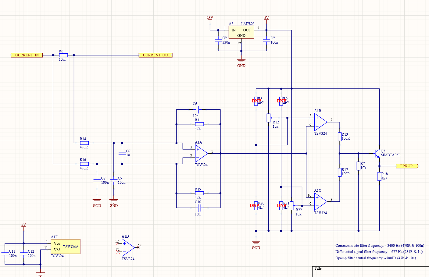 ----- **More about the circuit** The circuit is sensing (low side sensing for many reasons) current used to power up the lights with 28V(part of the schematics not shown here -> relay with LC filter on the output side to limit the inrush current). The nominal current flowing through R6 is around 0.2A but could be up to 1.5A in peaks(peaks last around 100ms). First opamp "A1A" is used to convert the differential signal seen on R6(around 200mV) to a single-ended signal with a ~300Hz. R14, C9, R16, C8, and C7 are here for diff and common mode filtering(cut-off frequencies shown in the bottom right corner of the picture). Using R12 and R22 around "A1B" and "A1C" I will trim the precise voltage values so that open circuit and overcurrent events flowing through R6 are detectable. The information whether the circuit is open or there is overcurrent will be reported through Q5 to another device(not on this PCB - most likely industrial computer 5V Input). ----- **Question** How would you position the TVS diodes around the "A1A" inputs so that circuit stays the same but become as immune to ESD events as possible? ESD that we are talking about here is +-15kV with 330R and 150pF model(IEC6100-4-2 Class 4).