Post History
Not a diff amp Something doesn't make sense here. You want A1A to act as a differential amplifier, but that's not how you wired it: Here is a real diff amp: Note how the right side of R1 is...
#1: Initial revision
by
 Olin Lathrop
·
2020-11-07T16:40:19Z (over 4 years ago)
Olin Lathrop
·
2020-11-07T16:40:19Z (over 4 years ago)
<h2>Not a diff amp</h2> Something doesn't make sense here. You want A1A to act as a differential amplifier, but that's not how you wired it: 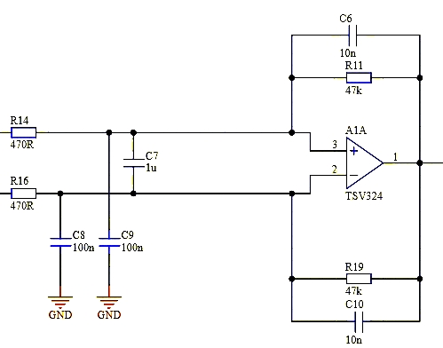 Here is a real diff amp: 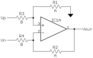 Note how the right side of R1 is tied to ground, not the opamp output. The diff amp above is really a 3-input circuit. The output is the difference between the two inputs at left, multiplied by the gain (A/B in this example), then added to the reference input. In my circuit the reference input is the right side of R1, which is tied to ground in this example. Therefore, the amplified difference output will be relative to ground. You have the reference input tied to the output. That makes the output indeterminate for ideal parts. All values of output satisfy the constraints when the inputs are equal. One way to see this is to analyze your circuit with the left ends of R14 and R16 tied to ground. What will the output be? Whatever value you pick for the output, it will be divided by the same amount at each opamp input. No matter what the output voltage is, the opamp inputs will be the same. <h2>TVSs</h2> You don't need any TVSs. The zap you specified (15 kV on 150 pF with 330 Ω in series) is going to disrupt the signal. Your only aim therefore is to protect the circuit from physical damage. You already have 470 Ω followed by 100 nF to ground on each input. That should be enough to limit short zaps to the point where the protection circuitry in the opamp can handle the rest. Your input capacitors are (100 nF)/(150 pF) = 667 times larger than the capacitance holding the static charge. That alone attenuates the 15 kV to 22.5 V. The input capacitors would only rise from 0 to 22.5 V with nothing else in the circuit. The time constant of the rise would be (330 Ω + 470 Ω)(100 nF) = 80 µs. Or, we can look at this in frequency space as a single pole low pass filter at 2 kHz. Either way, it should be clear that any active ESD protection circuitry in the opamp can easily react in the time necessary to clamp the voltage. I didn't look up your opamp since you didn't provide a datasheet link, so it's your job to check how its inputs are protected. But unless this device is unusual, there is no problem here to solve.