Post History
Don't put the "protective" series resistor: connect directly your regulated power supply to the diode (with a short wire) and measure the current: the voltage regulator is all what you need to prot...
#9: Post edited
by
 coquelicot
·
2020-11-22T21:22:36Z (over 4 years ago)
coquelicot
·
2020-11-22T21:22:36Z (over 4 years ago)
wrong op-amp in schematic
- Don't put the "protective" series resistor: connect directly your regulated power supply to the diode (with a short wire) and measure the current: the voltage regulator is all what you need to protect the diode and ensures you are not missing the negative resistance part.
- Then you increase very slowly the voltage until the curve is completed.
- I once traced the VI curve of a a Gunn diode that way, with a stupid LM317 regulator. The only difference is that the Gunn diode has a higher voltage graph.
- But since you say you have a well regulated power supply that allows fine tuning from 0V to 5V (at least), there should be no problem.
- Otherwise, it is also easy to build an adjustable regulator for low voltages by driving a rail to rail opamp follower with a pot. This is sufficient for this task, since only few tens of mA are needed.
- -----------------------------------------------------------------------
- >Now only the milliammeter resistance can create a problem.
- Not a problem at all if your power supply has an integrated ammeter.
- But even without that, it is unlikely that the few tens of millivolts drop from the milliammeter would cause instability and missing the negative resistance part of the diode. Of course, the voltage should be measured at the terminals of the diode, and not after the milliammeter!
- OR, with the pot-follower solution above, here is the schematic:
- 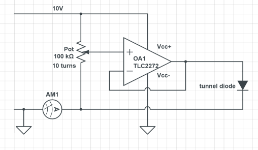
- The voltage is measured at the terminals of the diode with the multimeter.
- ----------------------------------------------------------------------
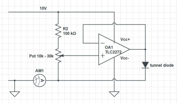
- >I'd break the pot up into a fixed resistor for the top part, and a pot to only allow up to a volt or so max for the bottom part. That reduces the settings that might cause damage, in addition to giving you higher adjustment resolution
- In other words:
- Yes, of course. My circuit was just "quick and dirty", but if it has to be used several times, it should be made safe as suggested by Olin.
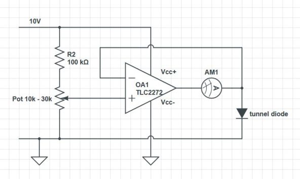
- Circuit Fantasist has also suggested the following:
- This should work as well, despite I somewhat dislike the idea to add inductance inside the control loop (due to the terminals of the ammeter, or worse, due to the ammeter itself if an analog ammeter is used), near a negative resistance.
- Don't put the "protective" series resistor: connect directly your regulated power supply to the diode (with a short wire) and measure the current: the voltage regulator is all what you need to protect the diode and ensures you are not missing the negative resistance part.
- Then you increase very slowly the voltage until the curve is completed.
- I once traced the VI curve of a a Gunn diode that way, with a stupid LM317 regulator. The only difference is that the Gunn diode has a higher voltage graph.
- But since you say you have a well regulated power supply that allows fine tuning from 0V to 5V (at least), there should be no problem.
- Otherwise, it is also easy to build an adjustable regulator for low voltages by driving a rail to rail opamp follower with a pot. This is sufficient for this task, since only few tens of mA are needed.
- -----------------------------------------------------------------------
- >Now only the milliammeter resistance can create a problem.
- Not a problem at all if your power supply has an integrated ammeter.
- But even without that, it is unlikely that the few tens of millivolts drop from the milliammeter would cause instability and missing the negative resistance part of the diode. Of course, the voltage should be measured at the terminals of the diode, and not after the milliammeter!
- OR, with the pot-follower solution above, here is the schematic:
- 
- The voltage is measured at the terminals of the diode with the multimeter.
- ----------------------------------------------------------------------
- >I'd break the pot up into a fixed resistor for the top part, and a pot to only allow up to a volt or so max for the bottom part. That reduces the settings that might cause damage, in addition to giving you higher adjustment resolution
- In other words:
- 
- Yes, of course. My circuit was just "quick and dirty", but if it has to be used several times, it should be made safe as suggested by Olin.
- Circuit Fantasist has also suggested the following:
- 
- This should work as well, despite I somewhat dislike the idea to add inductance inside the control loop (due to the terminals of the ammeter, or worse, due to the ammeter itself if an analog ammeter is used), near a negative resistance.
#8: Post edited
by
coquelicot
·
2020-11-22T16:53:54Z (over 4 years ago)
- Don't put the "protective" series resistor: connect directly your regulated power supply to the diode (with a short wire) and measure the current: the voltage regulator is all what you need to protect the diode and ensures you are not missing the negative resistance part.
- Then you increase very slowly the voltage until the curve is completed.
- I once traced the VI curve of a a Gunn diode that way, with a stupid LM317 regulator. The only difference is that the Gunn diode has a higher voltage graph.
- But since you say you have a well regulated power supply that allows fine tuning from 0V to 5V (at least), there should be no problem.
- Otherwise, it is also easy to build an adjustable regulator for low voltages by driving a rail to rail opamp follower with a pot. This is sufficient for this task, since only few tens of mA are needed.
- -----------------------------------------------------------------------
- >Now only the milliammeter resistance can create a problem.
- Not a problem at all if your power supply has an integrated ammeter.
- But even without that, it is unlikely that the few tens of millivolts drop from the milliammeter would cause instability and missing the negative resistance part of the diode. Of course, the voltage should be measured at the terminals of the diode, and not after the milliammeter!
- OR, with the pot-follower solution above, here is the schematic:
- 
- The voltage is measured at the terminals of the diode with the multimeter.
- ----------------------------------------------------------------------
- >I'd break the pot up into a fixed resistor for the top part, and a pot to only allow up to a volt or so max for the bottom part. That reduces the settings that might cause damage, in addition to giving you higher adjustment resolution
- In other words:
- 
- Yes, of course. My circuit was just "quick and dirty", but if it has to be used several times, it should be made safe as suggested by Olin.
- Circuit Fantasist has also suggested the following:
- 
This should work as well, despite I somewhat dislike the idea to add inductance inside the control loop (due to the terminals of the ammeter, or worse, due to the ammeter itself if an analog ammeter is used).
- Don't put the "protective" series resistor: connect directly your regulated power supply to the diode (with a short wire) and measure the current: the voltage regulator is all what you need to protect the diode and ensures you are not missing the negative resistance part.
- Then you increase very slowly the voltage until the curve is completed.
- I once traced the VI curve of a a Gunn diode that way, with a stupid LM317 regulator. The only difference is that the Gunn diode has a higher voltage graph.
- But since you say you have a well regulated power supply that allows fine tuning from 0V to 5V (at least), there should be no problem.
- Otherwise, it is also easy to build an adjustable regulator for low voltages by driving a rail to rail opamp follower with a pot. This is sufficient for this task, since only few tens of mA are needed.
- -----------------------------------------------------------------------
- >Now only the milliammeter resistance can create a problem.
- Not a problem at all if your power supply has an integrated ammeter.
- But even without that, it is unlikely that the few tens of millivolts drop from the milliammeter would cause instability and missing the negative resistance part of the diode. Of course, the voltage should be measured at the terminals of the diode, and not after the milliammeter!
- OR, with the pot-follower solution above, here is the schematic:
- 
- The voltage is measured at the terminals of the diode with the multimeter.
- ----------------------------------------------------------------------
- >I'd break the pot up into a fixed resistor for the top part, and a pot to only allow up to a volt or so max for the bottom part. That reduces the settings that might cause damage, in addition to giving you higher adjustment resolution
- In other words:
- 
- Yes, of course. My circuit was just "quick and dirty", but if it has to be used several times, it should be made safe as suggested by Olin.
- Circuit Fantasist has also suggested the following:
- 
- This should work as well, despite I somewhat dislike the idea to add inductance inside the control loop (due to the terminals of the ammeter, or worse, due to the ammeter itself if an analog ammeter is used), near a negative resistance.
#7: Post edited
by
coquelicot
·
2020-11-22T16:48:13Z (over 4 years ago)
- Don't put the "protective" series resistor: connect directly your regulated power supply to the diode (with a short wire) and measure the current: the voltage regulator is all what you need to protect the diode and ensures you are not missing the negative resistance part.
- Then you increase very slowly the voltage until the curve is completed.
- I once traced the VI curve of a a Gunn diode that way, with a stupid LM317 regulator. The only difference is that the Gunn diode has a higher voltage graph.
- But since you say you have a well regulated power supply that allows fine tuning from 0V to 5V (at least), there should be no problem.
- Otherwise, it is also easy to build an adjustable regulator for low voltages by driving a rail to rail opamp follower with a pot. This is sufficient for this task, since only few tens of mA are needed.
- >Now only the milliammeter resistance can create a problem.
- Not a problem at all if your power supply has an integrated ammeter.
- But even without that, it is unlikely that the few tens of millivolts drop from the milliammeter would cause instability and missing the negative resistance part of the diode. Of course, the voltage should be measured at the terminals of the diode, and not after the milliammeter!
- OR, with the pot-follower solution above, here is the schematic:
- 
- The voltage is measured at the terminals of the diode with the multimeter.
- Don't put the "protective" series resistor: connect directly your regulated power supply to the diode (with a short wire) and measure the current: the voltage regulator is all what you need to protect the diode and ensures you are not missing the negative resistance part.
- Then you increase very slowly the voltage until the curve is completed.
- I once traced the VI curve of a a Gunn diode that way, with a stupid LM317 regulator. The only difference is that the Gunn diode has a higher voltage graph.
- But since you say you have a well regulated power supply that allows fine tuning from 0V to 5V (at least), there should be no problem.
- Otherwise, it is also easy to build an adjustable regulator for low voltages by driving a rail to rail opamp follower with a pot. This is sufficient for this task, since only few tens of mA are needed.
- -----------------------------------------------------------------------
- >Now only the milliammeter resistance can create a problem.
- Not a problem at all if your power supply has an integrated ammeter.
- But even without that, it is unlikely that the few tens of millivolts drop from the milliammeter would cause instability and missing the negative resistance part of the diode. Of course, the voltage should be measured at the terminals of the diode, and not after the milliammeter!
- OR, with the pot-follower solution above, here is the schematic:
- 
- The voltage is measured at the terminals of the diode with the multimeter.
- ----------------------------------------------------------------------
- >I'd break the pot up into a fixed resistor for the top part, and a pot to only allow up to a volt or so max for the bottom part. That reduces the settings that might cause damage, in addition to giving you higher adjustment resolution
- In other words:
- 
- Yes, of course. My circuit was just "quick and dirty", but if it has to be used several times, it should be made safe as suggested by Olin.
- Circuit Fantasist has also suggested the following:
- 
- This should work as well, despite I somewhat dislike the idea to add inductance inside the control loop (due to the terminals of the ammeter, or worse, due to the ammeter itself if an analog ammeter is used).
#6: Post edited
by
coquelicot
·
2020-11-22T09:42:10Z (over 4 years ago)
- Don't put the "protective" series resistor: connect directly your regulated power supply to the diode (with a short wire) and measure the current: the voltage regulator is all what you need to protect the diode and ensures you are not missing the negative resistance part.
- Then you increase very slowly the voltage until the curve is completed.
- I once traced the VI curve of a a Gunn diode that way, with a stupid LM317 regulator. The only difference is that the Gunn diode has a higher voltage graph.
- But since you say you have a well regulated power supply that allows fine tuning from 0V to 5V (at least), there should be no problem.
- Otherwise, it is also easy to build an adjustable regulator for low voltages by driving a rail to rail opamp follower with a pot. This is sufficient for this task, since only few tens of mA are needed.
- >Now only the milliammeter resistance can create a problem.
- Not a problem at all if your power supply has an integrated ammeter.
- But even without that, it is unlikely that the few tens of millivolts drop from the milliammeter would cause instability and missing the negative resistance part of the diode. Of course, the voltage should be measured at the terminals of the diode, and not after the milliammeter!
- OR, with the pot-follower solution above, here is the schematic:
- 
The voltage is measured at the terminal of the diode with the multimeter.
- Don't put the "protective" series resistor: connect directly your regulated power supply to the diode (with a short wire) and measure the current: the voltage regulator is all what you need to protect the diode and ensures you are not missing the negative resistance part.
- Then you increase very slowly the voltage until the curve is completed.
- I once traced the VI curve of a a Gunn diode that way, with a stupid LM317 regulator. The only difference is that the Gunn diode has a higher voltage graph.
- But since you say you have a well regulated power supply that allows fine tuning from 0V to 5V (at least), there should be no problem.
- Otherwise, it is also easy to build an adjustable regulator for low voltages by driving a rail to rail opamp follower with a pot. This is sufficient for this task, since only few tens of mA are needed.
- >Now only the milliammeter resistance can create a problem.
- Not a problem at all if your power supply has an integrated ammeter.
- But even without that, it is unlikely that the few tens of millivolts drop from the milliammeter would cause instability and missing the negative resistance part of the diode. Of course, the voltage should be measured at the terminals of the diode, and not after the milliammeter!
- OR, with the pot-follower solution above, here is the schematic:
- 
- The voltage is measured at the terminals of the diode with the multimeter.
#5: Post edited
by
coquelicot
·
2020-11-22T09:41:51Z (over 4 years ago)
- Don't put the "protective" series resistor: connect directly your regulated power supply to the diode (with a short wire) and measure the current: the voltage regulator is all what you need to protect the diode and ensures you are not missing the negative resistance part.
- Then you increase very slowly the voltage until the curve is completed.
- I once traced the VI curve of a a Gunn diode that way, with a stupid LM317 regulator. The only difference is that the Gunn diode has a higher voltage graph.
- But since you say you have a well regulated power supply that allows fine tuning from 0V to 5V (at least), there should be no problem.
- Otherwise, it is also easy to build an adjustable regulator for low voltages by driving a rail to rail opamp follower with a pot. This is sufficient for this task, since only few tens of mA are needed.
- >Now only the milliammeter resistance can create a problem.
- Not a problem at all if your power supply has an integrated ammeter.
- But even without that, it is unlikely that the few tens of millivolts drop from the milliammeter would cause instability and missing the negative resistance part of the diode. Of course, the voltage should be measured at the terminals of the diode, and not after the milliammeter!
- OR, with the pot-follower solution above, here is the schematic:
- 
Of course, the voltage is measured at the terminal of the diode with the multimeter.
- Don't put the "protective" series resistor: connect directly your regulated power supply to the diode (with a short wire) and measure the current: the voltage regulator is all what you need to protect the diode and ensures you are not missing the negative resistance part.
- Then you increase very slowly the voltage until the curve is completed.
- I once traced the VI curve of a a Gunn diode that way, with a stupid LM317 regulator. The only difference is that the Gunn diode has a higher voltage graph.
- But since you say you have a well regulated power supply that allows fine tuning from 0V to 5V (at least), there should be no problem.
- Otherwise, it is also easy to build an adjustable regulator for low voltages by driving a rail to rail opamp follower with a pot. This is sufficient for this task, since only few tens of mA are needed.
- >Now only the milliammeter resistance can create a problem.
- Not a problem at all if your power supply has an integrated ammeter.
- But even without that, it is unlikely that the few tens of millivolts drop from the milliammeter would cause instability and missing the negative resistance part of the diode. Of course, the voltage should be measured at the terminals of the diode, and not after the milliammeter!
- OR, with the pot-follower solution above, here is the schematic:
- 
- The voltage is measured at the terminal of the diode with the multimeter.
#4: Post edited
by
coquelicot
·
2020-11-22T09:34:07Z (over 4 years ago)
- Don't put the "protective" series resistor: connect directly your regulated power supply to the diode (with a short wire) and measure the current: the voltage regulator is all what you need to protect the diode and ensures you are not missing the negative resistance part.
- Then you increase very slowly the voltage until the curve is completed.
- I once traced the VI curve of a a Gunn diode that way, with a stupid LM317 regulator. The only difference is that the Gunn diode has a higher voltage graph.
- But since you say you have a well regulated power supply that allows fine tuning from 0V to 5V (at least), there should be no problem.
- Otherwise, it is also easy to build an adjustable regulator for low voltages by driving a rail to rail opamp follower with a pot. This is sufficient for this task, since only few tens of mA are needed.
- >Now only the milliammeter resistance can create a problem.
- Not a problem at all if your power supply has an integrated ammeter.
- But even without that, it is unlikely that the few tens of millivolts drop from the milliammeter would cause instability and missing the negative resistance part of the diode. Of course, the voltage should be measured at the terminals of the diode, and not after the milliammeter!
- OR, with the pot-follower solution above, here is the schematic:
- 
- Of course, the voltage is measured at the terminal of the diode with the multimeter.
#3: Post edited
by
coquelicot
·
2020-11-21T22:43:27Z (over 4 years ago)
- Don't put the "protective" series resistor: connect directly your regulated power supply to the diode (with a short wire) and measure the current: the voltage regulator is all what you need to protect the diode and ensures you are not missing the negative resistance part.
- I once traced the VI curve of a a Gunn diode that way, with a stupid LM317 regulator. The only difference is that the Gunn diode has a higher voltage graph.
- But since you say you have a well regulated power supply that allows fine tuning from 0V to 5V (at least), there should be no problem.
- Otherwise, it is also easy to build an adjustable regulator for low voltages by driving a rail to rail opamp follower with a pot. This is sufficient for this task, since only few tens of mA are needed.
- Don't put the "protective" series resistor: connect directly your regulated power supply to the diode (with a short wire) and measure the current: the voltage regulator is all what you need to protect the diode and ensures you are not missing the negative resistance part.
- Then you increase very slowly the voltage until the curve is completed.
- I once traced the VI curve of a a Gunn diode that way, with a stupid LM317 regulator. The only difference is that the Gunn diode has a higher voltage graph.
- But since you say you have a well regulated power supply that allows fine tuning from 0V to 5V (at least), there should be no problem.
- Otherwise, it is also easy to build an adjustable regulator for low voltages by driving a rail to rail opamp follower with a pot. This is sufficient for this task, since only few tens of mA are needed.
#2: Post edited
by
coquelicot
·
2020-11-21T22:40:47Z (over 4 years ago)
Don't put the "protective" series resistor: connect directly your regulated power supply to the diode (with a short wire) and measure the current: the voltage regulator is all what you need to protect the diode.- I once traced the VI curve of a a Gunn diode that way, with a stupid LM317 regulator. The only difference is that the Gunn diode has a higher voltage graph.
- But since you say you have a well regulated power supply that allows fine tuning from 0V to 5V (at least), there should be no problem.
- Otherwise, it is also easy to build an adjustable regulator for low voltages by driving a rail to rail opamp follower with a pot. This is sufficient for this task, since only few tens of mA are needed.
- Don't put the "protective" series resistor: connect directly your regulated power supply to the diode (with a short wire) and measure the current: the voltage regulator is all what you need to protect the diode and ensures you are not missing the negative resistance part.
- I once traced the VI curve of a a Gunn diode that way, with a stupid LM317 regulator. The only difference is that the Gunn diode has a higher voltage graph.
- But since you say you have a well regulated power supply that allows fine tuning from 0V to 5V (at least), there should be no problem.
- Otherwise, it is also easy to build an adjustable regulator for low voltages by driving a rail to rail opamp follower with a pot. This is sufficient for this task, since only few tens of mA are needed.
#1: Initial revision
by
coquelicot
·
2020-11-21T22:37:59Z (over 4 years ago)
Don't put the "protective" series resistor: connect directly your regulated power supply to the diode (with a short wire) and measure the current: the voltage regulator is all what you need to protect the diode.

I once traced the VI curve of a a Gunn diode that way, with a stupid LM317 regulator. The only difference is that the Gunn diode has a higher voltage graph.

But since you say you have a well regulated power supply that allows fine tuning from 0V to 5V (at least), there should be no problem.

Otherwise, it is also easy to build an adjustable regulator for low voltages by driving a rail to rail opamp follower with a pot. This is sufficient for this task, since only few tens of mA are needed.