Post History
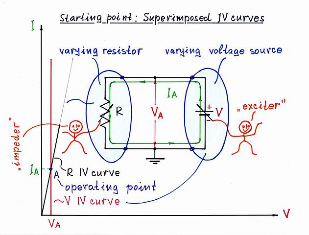
Setup We can best understand the behavior of the tunnel diode in the region with negative resistance if we imagine it as a self-variable (dynamic) resistor R driven by a variable voltage source V ...
#20: Post edited
by
 Circuit fantasist
·
2020-12-13T21:10:59Z (over 4 years ago)
Circuit fantasist
·
2020-12-13T21:10:59Z (over 4 years ago)
Explaining the compensating technique in terms of resistances
- Setup
- -----
- We can best understand the behavior of the tunnel diode in the region with negative resistance if we imagine it as a _self-variable_ (_dynamic_) resistor R driven by a variable voltage source V - Fig. 1. If OP has a subtle sense of humor, I suggest we conduct this experiment in the form of a fun (but useful) game where he is the voltage source and I am the "tunnel diode":)
- 
- Fig. 1. A setup for measuring the tunnel diode IV curve in the negative resistance region ([Wikibooks](https://en.wikibooks.org/wiki/Circuit_Idea/Negative_Differential_Resistance#/media/File:Iv_curves_N_1000.jpg))
- Graphical representation
- ------------------------
- The _voltage VA across_ and the _current IA through_ the two elements are the same. So their IV curves can be superimposed on the same coordinate system - Fig. 2. The IV curve of the variable resistor is a straight line (in orange) beginning from the coordinate origin and having a slope depending on the instant (_static_) resistance R. The IV curve of the input voltage source is a vertical line (in red) shifted to the right from the Y-axis. The intersection point A (aka _operating point_) represents the instant magnitudes of the current IA and the voltage VA.
- 
- Fig. 2. The graphical representation of the circuit operation as two superimposed IV curves ([Wikibooks](https://en.wikibooks.org/wiki/Circuit_Idea/Negative_Differential_Resistance#/media/File:Linear_voltage-driven_1000.jpg))
- Operation
- ---------
- **1. Low positive resistance region.** When OP gradually increases the input voltage from zero to the beginning of the negative resistance region, I keep a low constant resistance R... and OP (i.e., the voltage source) imagines it as a steep line (IV curve).
- **2. Negative resistance region.** When reaching the negative resistance region, I decide to play a trick with OP and begin increasing R vigorously while he gradually increases the input voltage. As a result, in Ohm's law I = V/R, both V and R change in opposite directions and with different rates of change. The resistance rate is higher than the voltage rate so the current decreases and OP sees a negative resistance. In Fig. 2, my (R, tunnel diode) IV curve begins rotating clockwise; the operating point A moves down and pictures the negative resistance part of the tunnel diode N-shaped IV curve.
- **3. High positive resistance region.** After the negative resistance region, OP continues increasing the input voltage. My resistor possesses high positive resistance and OP imagines it as a sloping IV curve.
- More considerations
- -------------------
- Let's see what is the most important to measure the tunnel diode IV curve. IMO this is not the scope. You have to see that when increasing the voltage across the diode, the current through it decreases. For this purpose, first at all, you have to remove (destroy, neutralize) any resistance in series. Here is my philosophy about how we can do it...
- **The problem.** What is this resistance? First, this is the internal resistance of the voltage source and next, this is the ammeter resistance (as you provably now, VOM measure the current by measuring the voltage drop across a small resistance). How do we do this magic? The usual answer is, "It is very simple, just apply a negative feedback". Yes, but you probably are not satisfied with ready-made formal explanations and you want to understand the idea behind all this. Here is what it is ...
- **Solution.** To zero a resistance actually means to zero the voltage drop across it (V = I.R = 0). The natural way is to replace the existing resistance with a "piece of wire"; then really V = I.0 = 0. Only, we cannot do it in this way. However, since we are inventive enough, we decide to do it in an artificial way - by adding a voltage equal to the voltage drop in a series manner, according to KVL. As a result, the total voltage across this network will be zero... as though the resistance is zero. Wonderful, isn't it?
- We can add the compensating voltage in two ways:
- _1. Increasing VIN with VR._ First, we can make the input voltage source to raise its voltage with the value of the voltage drop. We can do it by applying a series negative feedback to an op-amp and putting (hiding) the ammeter resistance into the feedback loop. This idea is implemented in Olin's and coquelicot's answers. A disadvantage of this solution is that the ammeter (ADC) is floating. Also, you can want to test another device by current; then the device will be floating.
- _2. Adding VR to VIN._ The second idea is just amazing - instead to increase the input voltage with VR, we decide to add a compensating voltage VR to the input voltage. This means to connect an additional voltage source in series to the diode so that its voltage adds to the input voltage according to KVL. For this purpose, its voltage must be negative in regards to ground (you can see for yourself if you travel along the loop). The sum of the compensating voltage and the voltage drop across R is zero (VR - VR = 0) and the so-called _virtual ground_ appears.
- **Implementation.** Thus you have two possibilities to artificially zero the undesired resistance - by a non-inverting configuration or by an inverting one. I prefer to use the second; [this old setup](https://photos.app.goo.gl/5u7nt1YxKV3iJ9kQA) from 90s is implemented this way (here is a [movie](https://photos.app.goo.gl/6vFc15pUverVjZbe9) showing how a rectifying diode can be investigated by voltage). It is actually an inverting amplifier with buffered input and output. For your purposes, you have to connect the tunnel diode in the place of R1 and the ammeter (VOM or movement) in the place of R2. If you want to measure the current by a grounded ADC or a microcontroller port, then use the op-amp output voltage as a measure of the current. The only problem is that it is negative (I = -Vout/R).
- See also
- --------
- [Demystifying the Negative Differential Resistance Phenomenon](https://en.wikibooks.org/wiki/Circuit_Idea/Negative_Differential_Resistance) (a Wikibooks story about NDR)
- [Art of Electronics - Zener Diode Example](https://electronics.stackexchange.com/a/468086/61398) (the same explanation about the dynamic resistance but in the case of a Zener diode)
- [Voltage compensation](https://en.wikibooks.org/wiki/Circuit_Idea/Voltage_Compensation) (a Wikibooks story about the philosophy behind op-amp inverting circuits)
- Setup
- -----
- We can best understand the behavior of the tunnel diode in the region with negative resistance if we imagine it as a _self-variable_ (_dynamic_) resistor R driven by a variable voltage source V - Fig. 1. If OP has a subtle sense of humor, I suggest we conduct this experiment in the form of a fun (but useful) game where he is the voltage source and I am the "tunnel diode":)
- 
- Fig. 1. A setup for measuring the tunnel diode IV curve in the negative resistance region ([Wikibooks](https://en.wikibooks.org/wiki/Circuit_Idea/Negative_Differential_Resistance#/media/File:Iv_curves_N_1000.jpg))
- Graphical representation
- ------------------------
- The _voltage VA across_ and the _current IA through_ the two elements are the same. So their IV curves can be superimposed on the same coordinate system - Fig. 2. The IV curve of the variable resistor is a straight line (in orange) beginning from the coordinate origin and having a slope depending on the instant (_static_) resistance R. The IV curve of the input voltage source is a vertical line (in red) shifted to the right from the Y-axis. The intersection point A (aka _operating point_) represents the instant magnitudes of the current IA and the voltage VA.
- 
- Fig. 2. The graphical representation of the circuit operation as two superimposed IV curves ([Wikibooks](https://en.wikibooks.org/wiki/Circuit_Idea/Negative_Differential_Resistance#/media/File:Linear_voltage-driven_1000.jpg))
- Operation
- ---------
- **1. Low positive resistance region.** When OP gradually increases the input voltage from zero to the beginning of the negative resistance region, I keep a low constant resistance R... and OP (i.e., the voltage source) imagines it as a steep line (IV curve).
- **2. Negative resistance region.** When reaching the negative resistance region, I decide to play a trick with OP and begin increasing R vigorously while he gradually increases the input voltage. As a result, in Ohm's law I = V/R, both V and R change in opposite directions and with different rates of change. The resistance rate is higher than the voltage rate so the current decreases and OP sees a negative resistance. In Fig. 2, my (R, tunnel diode) IV curve begins rotating clockwise; the operating point A moves down and pictures the negative resistance part of the tunnel diode N-shaped IV curve.
- **3. High positive resistance region.** After the negative resistance region, OP continues increasing the input voltage. My resistor possesses high positive resistance and OP imagines it as a sloping IV curve.
- More considerations
- -------------------
- Let's see what is the most important to measure the tunnel diode IV curve. IMO this is not the scope. You have to see that when increasing the voltage across the diode, the current through it decreases. For this purpose, first at all, you have to remove (destroy, neutralize) any resistance in series. Here is my philosophy about how we can do it...
- **The problem.** What is this resistance? First, this is the internal resistance of the voltage source and next, this is the ammeter resistance (as you provably now, VOM measure the current by measuring the voltage drop across a small resistance). How do we do this magic? The usual answer is, "It is very simple, just apply a negative feedback". Yes, but you probably are not satisfied with ready-made formal explanations and you want to understand the idea behind all this. Here is what it is ...
- **Solution.** To zero a resistance actually means to zero the voltage drop across it (V = I.R = 0). The natural way is to replace the existing resistance with a "piece of wire"; then really V = I.0 = 0. Only, we cannot do it in this way. However, since we are inventive enough, we decide to do it in an artificial way - by adding a voltage equal to the voltage drop in a series manner, according to KVL. As a result, the total voltage across this network will be zero... as though the resistance is zero. Wonderful, isn't it?
- We can add the compensating voltage in two ways:
- _1. Increasing VIN with VR._ First, we can make the input voltage source to raise its voltage with the value of the voltage drop. We can do it by applying a series negative feedback to an op-amp and putting (hiding) the ammeter resistance into the feedback loop. This idea is implemented in Olin's and coquelicot's answers. A disadvantage of this solution is that the ammeter (ADC) is floating. Also, you can want to test another device by current; then the device will be floating.
- _2. Adding VR to VIN._ The second idea is just amazing - instead to increase the input voltage with VR, we decide to add a compensating voltage VR to the input voltage. This means to connect an additional voltage source in series to the diode so that its voltage adds to the input voltage according to KVL. For this purpose, its voltage must be negative in regards to ground (you can see for yourself if you travel along the loop). The sum of the compensating voltage and the voltage drop across R is zero (VR - VR = 0) and the so-called _virtual ground_ appears.
- We can explain this technique in *terms of resistances*. The op-amp output can be considered as a *negative resistor" with equivalent but negative resistance -R that is added to the positive resistance R. The result is zero resistance.
- **Implementation.** Thus you have two possibilities to artificially zero the undesired resistance - by a non-inverting configuration or by an inverting one. I prefer to use the second; [this old setup](https://photos.app.goo.gl/5u7nt1YxKV3iJ9kQA) from 90s is implemented this way (here is a [movie](https://photos.app.goo.gl/6vFc15pUverVjZbe9) showing how a rectifying diode can be investigated by voltage). It is actually an inverting amplifier with buffered input and output. For your purposes, you have to connect the tunnel diode in the place of R1 and the ammeter (VOM or movement) in the place of R2. If you want to measure the current by a grounded ADC or a microcontroller port, then use the op-amp output voltage as a measure of the current. The only problem is that it is negative (I = -Vout/R).
- See also
- --------
- [Demystifying the Negative Differential Resistance Phenomenon](https://en.wikibooks.org/wiki/Circuit_Idea/Negative_Differential_Resistance) (a Wikibooks story about NDR)
- [Art of Electronics - Zener Diode Example](https://electronics.stackexchange.com/a/468086/61398) (the same explanation about the dynamic resistance but in the case of a Zener diode)
- [Voltage compensation](https://en.wikibooks.org/wiki/Circuit_Idea/Voltage_Compensation) (a Wikibooks story about the philosophy behind op-amp inverting circuits)
#19: Post edited
by
Circuit fantasist
·
2020-12-13T12:59:51Z (over 4 years ago)
About virtual ground
- Setup
- -----
- We can best understand the behavior of the tunnel diode in the region with negative resistance if we imagine it as a _self-variable_ (_dynamic_) resistor R driven by a variable voltage source V - Fig. 1. If OP has a subtle sense of humor, I suggest we conduct this experiment in the form of a fun (but useful) game where he is the voltage source and I am the "tunnel diode":)
- 
- Fig. 1. A setup for measuring the tunnel diode IV curve in the negative resistance region ([Wikibooks](https://en.wikibooks.org/wiki/Circuit_Idea/Negative_Differential_Resistance#/media/File:Iv_curves_N_1000.jpg))
- Graphical representation
- ------------------------
- The _voltage VA across_ and the _current IA through_ the two elements are the same. So their IV curves can be superimposed on the same coordinate system - Fig. 2. The IV curve of the variable resistor is a straight line (in orange) beginning from the coordinate origin and having a slope depending on the instant (_static_) resistance R. The IV curve of the input voltage source is a vertical line (in red) shifted to the right from the Y-axis. The intersection point A (aka _operating point_) represents the instant magnitudes of the current IA and the voltage VA.
- 
- Fig. 2. The graphical representation of the circuit operation as two superimposed IV curves ([Wikibooks](https://en.wikibooks.org/wiki/Circuit_Idea/Negative_Differential_Resistance#/media/File:Linear_voltage-driven_1000.jpg))
- Operation
- ---------
- **1. Low positive resistance region.** When OP gradually increases the input voltage from zero to the beginning of the negative resistance region, I keep a low constant resistance R... and OP (i.e., the voltage source) imagines it as a steep line (IV curve).
- **2. Negative resistance region.** When reaching the negative resistance region, I decide to play a trick with OP and begin increasing R vigorously while he gradually increases the input voltage. As a result, in Ohm's law I = V/R, both V and R change in opposite directions and with different rates of change. The resistance rate is higher than the voltage rate so the current decreases and OP sees a negative resistance. In Fig. 2, my (R, tunnel diode) IV curve begins rotating clockwise; the operating point A moves down and pictures the negative resistance part of the tunnel diode N-shaped IV curve.
- **3. High positive resistance region.** After the negative resistance region, OP continues increasing the input voltage. My resistor possesses high positive resistance and OP imagines it as a sloping IV curve.
- More considerations
- -------------------
- Let's see what is the most important to measure the tunnel diode IV curve. IMO this is not the scope. You have to see that when increasing the voltage across the diode, the current through it decreases. For this purpose, first at all, you have to remove (destroy, neutralize) any resistance in series. Here is my philosophy about how we can do it...
- **The problem.** What is this resistance? First, this is the internal resistance of the voltage source and next, this is the ammeter resistance (as you provably now, VOM measure the current by measuring the voltage drop across a small resistance). How do we do this magic? The usual answer is, "It is very simple, just apply a negative feedback". Yes, but you probably are not satisfied with ready-made formal explanations and you want to understand the idea behind all this. Here is what it is ...
- **Solution.** To zero a resistance actually means to zero the voltage drop across it (V = I.R = 0). The natural way is to replace the existing resistance with a "piece of wire"; then really V = I.0 = 0. Only, we cannot do it in this way. However, since we are inventive enough, we decide to do it in an artificial way - by adding a voltage equal to the voltage drop in a series manner, according to KVL. As a result, the total voltage across this network will be zero... as though the resistance is zero. Wonderful, isn't it?
- We can add the compensating voltage in two ways:
- _1. Increasing VIN with VR._ First, we can make the input voltage source to raise its voltage with the value of the voltage drop. We can do it by applying a series negative feedback to an op-amp and putting (hiding) the ammeter resistance into the feedback loop. This idea is implemented in Olin's and coquelicot's answers. A disadvantage of this solution is that the ammeter (ADC) is floating. Also, you can want to test another device by current; then the device will be floating.
_2. Adding VR to VIN._ The second idea is just amazing - instead to increase the input voltage with VR, we decide to add a compensating voltage VR to the input voltage. This means to connect an additional voltage source in series to the diode so that its voltage adds to the input voltage according to KVL. For this purpose, its voltage must be negative in regards to ground (you can see for yourself if you travel along the loop).- **Implementation.** Thus you have two possibilities to artificially zero the undesired resistance - by a non-inverting configuration or by an inverting one. I prefer to use the second; [this old setup](https://photos.app.goo.gl/5u7nt1YxKV3iJ9kQA) from 90s is implemented this way (here is a [movie](https://photos.app.goo.gl/6vFc15pUverVjZbe9) showing how a rectifying diode can be investigated by voltage). It is actually an inverting amplifier with buffered input and output. For your purposes, you have to connect the tunnel diode in the place of R1 and the ammeter (VOM or movement) in the place of R2. If you want to measure the current by a grounded ADC or a microcontroller port, then use the op-amp output voltage as a measure of the current. The only problem is that it is negative (I = -Vout/R).
- See also
- --------
- [Demystifying the Negative Differential Resistance Phenomenon](https://en.wikibooks.org/wiki/Circuit_Idea/Negative_Differential_Resistance) (a Wikibooks story about NDR)
- [Art of Electronics - Zener Diode Example](https://electronics.stackexchange.com/a/468086/61398) (the same explanation about the dynamic resistance but in the case of a Zener diode)
- [Voltage compensation](https://en.wikibooks.org/wiki/Circuit_Idea/Voltage_Compensation) (a Wikibooks story about the philosophy behind op-amp inverting circuits)
- Setup
- -----
- We can best understand the behavior of the tunnel diode in the region with negative resistance if we imagine it as a _self-variable_ (_dynamic_) resistor R driven by a variable voltage source V - Fig. 1. If OP has a subtle sense of humor, I suggest we conduct this experiment in the form of a fun (but useful) game where he is the voltage source and I am the "tunnel diode":)
- 
- Fig. 1. A setup for measuring the tunnel diode IV curve in the negative resistance region ([Wikibooks](https://en.wikibooks.org/wiki/Circuit_Idea/Negative_Differential_Resistance#/media/File:Iv_curves_N_1000.jpg))
- Graphical representation
- ------------------------
- The _voltage VA across_ and the _current IA through_ the two elements are the same. So their IV curves can be superimposed on the same coordinate system - Fig. 2. The IV curve of the variable resistor is a straight line (in orange) beginning from the coordinate origin and having a slope depending on the instant (_static_) resistance R. The IV curve of the input voltage source is a vertical line (in red) shifted to the right from the Y-axis. The intersection point A (aka _operating point_) represents the instant magnitudes of the current IA and the voltage VA.
- 
- Fig. 2. The graphical representation of the circuit operation as two superimposed IV curves ([Wikibooks](https://en.wikibooks.org/wiki/Circuit_Idea/Negative_Differential_Resistance#/media/File:Linear_voltage-driven_1000.jpg))
- Operation
- ---------
- **1. Low positive resistance region.** When OP gradually increases the input voltage from zero to the beginning of the negative resistance region, I keep a low constant resistance R... and OP (i.e., the voltage source) imagines it as a steep line (IV curve).
- **2. Negative resistance region.** When reaching the negative resistance region, I decide to play a trick with OP and begin increasing R vigorously while he gradually increases the input voltage. As a result, in Ohm's law I = V/R, both V and R change in opposite directions and with different rates of change. The resistance rate is higher than the voltage rate so the current decreases and OP sees a negative resistance. In Fig. 2, my (R, tunnel diode) IV curve begins rotating clockwise; the operating point A moves down and pictures the negative resistance part of the tunnel diode N-shaped IV curve.
- **3. High positive resistance region.** After the negative resistance region, OP continues increasing the input voltage. My resistor possesses high positive resistance and OP imagines it as a sloping IV curve.
- More considerations
- -------------------
- Let's see what is the most important to measure the tunnel diode IV curve. IMO this is not the scope. You have to see that when increasing the voltage across the diode, the current through it decreases. For this purpose, first at all, you have to remove (destroy, neutralize) any resistance in series. Here is my philosophy about how we can do it...
- **The problem.** What is this resistance? First, this is the internal resistance of the voltage source and next, this is the ammeter resistance (as you provably now, VOM measure the current by measuring the voltage drop across a small resistance). How do we do this magic? The usual answer is, "It is very simple, just apply a negative feedback". Yes, but you probably are not satisfied with ready-made formal explanations and you want to understand the idea behind all this. Here is what it is ...
- **Solution.** To zero a resistance actually means to zero the voltage drop across it (V = I.R = 0). The natural way is to replace the existing resistance with a "piece of wire"; then really V = I.0 = 0. Only, we cannot do it in this way. However, since we are inventive enough, we decide to do it in an artificial way - by adding a voltage equal to the voltage drop in a series manner, according to KVL. As a result, the total voltage across this network will be zero... as though the resistance is zero. Wonderful, isn't it?
- We can add the compensating voltage in two ways:
- _1. Increasing VIN with VR._ First, we can make the input voltage source to raise its voltage with the value of the voltage drop. We can do it by applying a series negative feedback to an op-amp and putting (hiding) the ammeter resistance into the feedback loop. This idea is implemented in Olin's and coquelicot's answers. A disadvantage of this solution is that the ammeter (ADC) is floating. Also, you can want to test another device by current; then the device will be floating.
- _2. Adding VR to VIN._ The second idea is just amazing - instead to increase the input voltage with VR, we decide to add a compensating voltage VR to the input voltage. This means to connect an additional voltage source in series to the diode so that its voltage adds to the input voltage according to KVL. For this purpose, its voltage must be negative in regards to ground (you can see for yourself if you travel along the loop). The sum of the compensating voltage and the voltage drop across R is zero (VR - VR = 0) and the so-called _virtual ground_ appears.
- **Implementation.** Thus you have two possibilities to artificially zero the undesired resistance - by a non-inverting configuration or by an inverting one. I prefer to use the second; [this old setup](https://photos.app.goo.gl/5u7nt1YxKV3iJ9kQA) from 90s is implemented this way (here is a [movie](https://photos.app.goo.gl/6vFc15pUverVjZbe9) showing how a rectifying diode can be investigated by voltage). It is actually an inverting amplifier with buffered input and output. For your purposes, you have to connect the tunnel diode in the place of R1 and the ammeter (VOM or movement) in the place of R2. If you want to measure the current by a grounded ADC or a microcontroller port, then use the op-amp output voltage as a measure of the current. The only problem is that it is negative (I = -Vout/R).
- See also
- --------
- [Demystifying the Negative Differential Resistance Phenomenon](https://en.wikibooks.org/wiki/Circuit_Idea/Negative_Differential_Resistance) (a Wikibooks story about NDR)
- [Art of Electronics - Zener Diode Example](https://electronics.stackexchange.com/a/468086/61398) (the same explanation about the dynamic resistance but in the case of a Zener diode)
- [Voltage compensation](https://en.wikibooks.org/wiki/Circuit_Idea/Voltage_Compensation) (a Wikibooks story about the philosophy behind op-amp inverting circuits)
#18: Post edited
by
Circuit fantasist
·
2020-12-13T12:25:51Z (over 4 years ago)
Minor edit
- Setup
- -----
- We can best understand the behavior of the tunnel diode in the region with negative resistance if we imagine it as a _self-variable_ (_dynamic_) resistor R driven by a variable voltage source V - Fig. 1. If OP has a subtle sense of humor, I suggest we conduct this experiment in the form of a fun (but useful) game where he is the voltage source and I am the "tunnel diode":)
- 
- Fig. 1. A setup for measuring the tunnel diode IV curve in the negative resistance region ([Wikibooks](https://en.wikibooks.org/wiki/Circuit_Idea/Negative_Differential_Resistance#/media/File:Iv_curves_N_1000.jpg))
- Graphical representation
- ------------------------
- The _voltage VA across_ and the _current IA through_ the two elements are the same. So their IV curves can be superimposed on the same coordinate system - Fig. 2. The IV curve of the variable resistor is a straight line (in orange) beginning from the coordinate origin and having a slope depending on the instant (_static_) resistance R. The IV curve of the input voltage source is a vertical line (in red) shifted to the right from the Y-axis. The intersection point A (aka _operating point_) represents the instant magnitudes of the current IA and the voltage VA.
- 
- Fig. 2. The graphical representation of the circuit operation as two superimposed IV curves ([Wikibooks](https://en.wikibooks.org/wiki/Circuit_Idea/Negative_Differential_Resistance#/media/File:Linear_voltage-driven_1000.jpg))
- Operation
- ---------
- **1. Low positive resistance region.** When OP gradually increases the input voltage from zero to the beginning of the negative resistance region, I keep a low constant resistance R... and OP (i.e., the voltage source) imagines it as a steep line (IV curve).
- **2. Negative resistance region.** When reaching the negative resistance region, I decide to play a trick with OP and begin increasing R vigorously while he gradually increases the input voltage. As a result, in Ohm's law I = V/R, both V and R change in opposite directions and with different rates of change. The resistance rate is higher than the voltage rate so the current decreases and OP sees a negative resistance. In Fig. 2, my (R, tunnel diode) IV curve begins rotating clockwise; the operating point A moves down and pictures the negative resistance part of the tunnel diode N-shaped IV curve.
- **3. High positive resistance region.** After the negative resistance region, OP continues increasing the input voltage. My resistor possesses high positive resistance and OP imagines it as a sloping IV curve.
- More considerations
- -------------------
- Let's see what is the most important to measure the tunnel diode IV curve. IMO this is not the scope. You have to see that when increasing the voltage across the diode, the current through it decreases. For this purpose, first at all, you have to remove (destroy, neutralize) any resistance in series. Here is my philosophy about how we can do it...
- **The problem.** What is this resistance? First, this is the internal resistance of the voltage source and next, this is the ammeter resistance (as you provably now, VOM measure the current by measuring the voltage drop across a small resistance). How do we do this magic? The usual answer is, "It is very simple, just apply a negative feedback". Yes, but you probably are not satisfied with ready-made formal explanations and you want to understand the idea behind all this. Here is what it is ...
- **Solution.** To zero a resistance actually means to zero the voltage drop across it (V = I.R = 0). The natural way is to replace the existing resistance with a "piece of wire"; then really V = I.0 = 0. Only, we cannot do it in this way. However, since we are inventive enough, we decide to do it in an artificial way - by adding a voltage equal to the voltage drop in a series manner, according to KVL. As a result, the total voltage across this network will be zero... as though the resistance is zero. Wonderful, isn't it?
- We can add the compensating voltage in two ways:
- _1. Increasing VIN with VR._ First, we can make the input voltage source to raise its voltage with the value of the voltage drop. We can do it by applying a series negative feedback to an op-amp and putting (hiding) the ammeter resistance into the feedback loop. This idea is implemented in Olin's and coquelicot's answers. A disadvantage of this solution is that the ammeter (ADC) is floating. Also, you can want to test another device by current; then the device will be floating.
- _2. Adding VR to VIN._ The second idea is just amazing - instead to increase the input voltage with VR, we decide to add a compensating voltage VR to the input voltage. This means to connect an additional voltage source in series to the diode so that its voltage adds to the input voltage according to KVL. For this purpose, its voltage must be negative in regards to ground (you can see for yourself if you travel along the loop).
_3. Implementation._ Thus you have two possibilities to artificially zero the undesired resistance - by a non-inverting configuration or by an inverting one. I prefer to use the second; [this old setup](https://photos.app.goo.gl/5u7nt1YxKV3iJ9kQA) from 90s is implemented this way (here is a [movie](https://photos.app.goo.gl/6vFc15pUverVjZbe9) showing how a rectifying diode can be investigated by voltage). It is actually an inverting amplifier with buffered input and output. For your purposes, you have to connect the tunnel diode in the place of R1 and the ammeter (VOM or movement) in the place of R2. If you want to measure the current by a grounded ADC or a microcontroller port, then use the op-amp output voltage as a measure of the current. The only problem is that it is negative (I = -Vout/R).- See also
- --------
- [Demystifying the Negative Differential Resistance Phenomenon](https://en.wikibooks.org/wiki/Circuit_Idea/Negative_Differential_Resistance) (a Wikibooks story about NDR)
- [Art of Electronics - Zener Diode Example](https://electronics.stackexchange.com/a/468086/61398) (the same explanation about the dynamic resistance but in the case of a Zener diode)
- [Voltage compensation](https://en.wikibooks.org/wiki/Circuit_Idea/Voltage_Compensation) (a Wikibooks story about the philosophy behind op-amp inverting circuits)
- Setup
- -----
- We can best understand the behavior of the tunnel diode in the region with negative resistance if we imagine it as a _self-variable_ (_dynamic_) resistor R driven by a variable voltage source V - Fig. 1. If OP has a subtle sense of humor, I suggest we conduct this experiment in the form of a fun (but useful) game where he is the voltage source and I am the "tunnel diode":)
- 
- Fig. 1. A setup for measuring the tunnel diode IV curve in the negative resistance region ([Wikibooks](https://en.wikibooks.org/wiki/Circuit_Idea/Negative_Differential_Resistance#/media/File:Iv_curves_N_1000.jpg))
- Graphical representation
- ------------------------
- The _voltage VA across_ and the _current IA through_ the two elements are the same. So their IV curves can be superimposed on the same coordinate system - Fig. 2. The IV curve of the variable resistor is a straight line (in orange) beginning from the coordinate origin and having a slope depending on the instant (_static_) resistance R. The IV curve of the input voltage source is a vertical line (in red) shifted to the right from the Y-axis. The intersection point A (aka _operating point_) represents the instant magnitudes of the current IA and the voltage VA.
- 
- Fig. 2. The graphical representation of the circuit operation as two superimposed IV curves ([Wikibooks](https://en.wikibooks.org/wiki/Circuit_Idea/Negative_Differential_Resistance#/media/File:Linear_voltage-driven_1000.jpg))
- Operation
- ---------
- **1. Low positive resistance region.** When OP gradually increases the input voltage from zero to the beginning of the negative resistance region, I keep a low constant resistance R... and OP (i.e., the voltage source) imagines it as a steep line (IV curve).
- **2. Negative resistance region.** When reaching the negative resistance region, I decide to play a trick with OP and begin increasing R vigorously while he gradually increases the input voltage. As a result, in Ohm's law I = V/R, both V and R change in opposite directions and with different rates of change. The resistance rate is higher than the voltage rate so the current decreases and OP sees a negative resistance. In Fig. 2, my (R, tunnel diode) IV curve begins rotating clockwise; the operating point A moves down and pictures the negative resistance part of the tunnel diode N-shaped IV curve.
- **3. High positive resistance region.** After the negative resistance region, OP continues increasing the input voltage. My resistor possesses high positive resistance and OP imagines it as a sloping IV curve.
- More considerations
- -------------------
- Let's see what is the most important to measure the tunnel diode IV curve. IMO this is not the scope. You have to see that when increasing the voltage across the diode, the current through it decreases. For this purpose, first at all, you have to remove (destroy, neutralize) any resistance in series. Here is my philosophy about how we can do it...
- **The problem.** What is this resistance? First, this is the internal resistance of the voltage source and next, this is the ammeter resistance (as you provably now, VOM measure the current by measuring the voltage drop across a small resistance). How do we do this magic? The usual answer is, "It is very simple, just apply a negative feedback". Yes, but you probably are not satisfied with ready-made formal explanations and you want to understand the idea behind all this. Here is what it is ...
- **Solution.** To zero a resistance actually means to zero the voltage drop across it (V = I.R = 0). The natural way is to replace the existing resistance with a "piece of wire"; then really V = I.0 = 0. Only, we cannot do it in this way. However, since we are inventive enough, we decide to do it in an artificial way - by adding a voltage equal to the voltage drop in a series manner, according to KVL. As a result, the total voltage across this network will be zero... as though the resistance is zero. Wonderful, isn't it?
- We can add the compensating voltage in two ways:
- _1. Increasing VIN with VR._ First, we can make the input voltage source to raise its voltage with the value of the voltage drop. We can do it by applying a series negative feedback to an op-amp and putting (hiding) the ammeter resistance into the feedback loop. This idea is implemented in Olin's and coquelicot's answers. A disadvantage of this solution is that the ammeter (ADC) is floating. Also, you can want to test another device by current; then the device will be floating.
- _2. Adding VR to VIN._ The second idea is just amazing - instead to increase the input voltage with VR, we decide to add a compensating voltage VR to the input voltage. This means to connect an additional voltage source in series to the diode so that its voltage adds to the input voltage according to KVL. For this purpose, its voltage must be negative in regards to ground (you can see for yourself if you travel along the loop).
- **Implementation.** Thus you have two possibilities to artificially zero the undesired resistance - by a non-inverting configuration or by an inverting one. I prefer to use the second; [this old setup](https://photos.app.goo.gl/5u7nt1YxKV3iJ9kQA) from 90s is implemented this way (here is a [movie](https://photos.app.goo.gl/6vFc15pUverVjZbe9) showing how a rectifying diode can be investigated by voltage). It is actually an inverting amplifier with buffered input and output. For your purposes, you have to connect the tunnel diode in the place of R1 and the ammeter (VOM or movement) in the place of R2. If you want to measure the current by a grounded ADC or a microcontroller port, then use the op-amp output voltage as a measure of the current. The only problem is that it is negative (I = -Vout/R).
- See also
- --------
- [Demystifying the Negative Differential Resistance Phenomenon](https://en.wikibooks.org/wiki/Circuit_Idea/Negative_Differential_Resistance) (a Wikibooks story about NDR)
- [Art of Electronics - Zener Diode Example](https://electronics.stackexchange.com/a/468086/61398) (the same explanation about the dynamic resistance but in the case of a Zener diode)
- [Voltage compensation](https://en.wikibooks.org/wiki/Circuit_Idea/Voltage_Compensation) (a Wikibooks story about the philosophy behind op-amp inverting circuits)
#17: Post edited
by
Circuit fantasist
·
2020-12-13T12:24:00Z (over 4 years ago)
Structuring
- Setup
- -----
- We can best understand the behavior of the tunnel diode in the region with negative resistance if we imagine it as a _self-variable_ (_dynamic_) resistor R driven by a variable voltage source V - Fig. 1. If OP has a subtle sense of humor, I suggest we conduct this experiment in the form of a fun (but useful) game where he is the voltage source and I am the "tunnel diode":)
- 
- Fig. 1. A setup for measuring the tunnel diode IV curve in the negative resistance region ([Wikibooks](https://en.wikibooks.org/wiki/Circuit_Idea/Negative_Differential_Resistance#/media/File:Iv_curves_N_1000.jpg))
- Graphical representation
- ------------------------
- The _voltage VA across_ and the _current IA through_ the two elements are the same. So their IV curves can be superimposed on the same coordinate system - Fig. 2. The IV curve of the variable resistor is a straight line (in orange) beginning from the coordinate origin and having a slope depending on the instant (_static_) resistance R. The IV curve of the input voltage source is a vertical line (in red) shifted to the right from the Y-axis. The intersection point A (aka _operating point_) represents the instant magnitudes of the current IA and the voltage VA.
- 
- Fig. 2. The graphical representation of the circuit operation as two superimposed IV curves ([Wikibooks](https://en.wikibooks.org/wiki/Circuit_Idea/Negative_Differential_Resistance#/media/File:Linear_voltage-driven_1000.jpg))
- Operation
- ---------
- **1. Low positive resistance region.** When OP gradually increases the input voltage from zero to the beginning of the negative resistance region, I keep a low constant resistance R... and OP (i.e., the voltage source) imagines it as a steep line (IV curve).
- **2. Negative resistance region.** When reaching the negative resistance region, I decide to play a trick with OP and begin increasing R vigorously while he gradually increases the input voltage. As a result, in Ohm's law I = V/R, both V and R change in opposite directions and with different rates of change. The resistance rate is higher than the voltage rate so the current decreases and OP sees a negative resistance. In Fig. 2, my (R, tunnel diode) IV curve begins rotating clockwise; the operating point A moves down and pictures the negative resistance part of the tunnel diode N-shaped IV curve.
- **3. High positive resistance region.** After the negative resistance region, OP continues increasing the input voltage. My resistor possesses high positive resistance and OP imagines it as a sloping IV curve.
- More considerations
- -------------------
- Let's see what is the most important to measure the tunnel diode IV curve. IMO this is not the scope. You have to see that when increasing the voltage across the diode, the current through it decreases. For this purpose, first at all, you have to remove (destroy, neutralize) any resistance in series. Here is my philosophy about how we can do it...
What is this resistance? First, this is the internal resistance of the voltage source and next, this is the ammeter resistance (as you provably now, VOM measure the current by measuring the voltage drop across a small resistance). How do we do this magic? The usual answer is, "It is very simple, just apply a negative feedback". Yes, but you probably are not satisfied with ready-made formal explanations and you want to understand the idea behind all this. Here is what it is ...To zero a resistance actually means to zero the voltage drop across it (V = I.R = 0). The natural way is to replace the existing resistance with a "piece of wire"; then really V = I.0 = 0. Only, we cannot do it in this way. However, since we are inventive enough, we decide to do it in an artificial way - by adding a voltage equal to the voltage drop in a series manner, according to KVL. As a result, the total voltage across this network will be zero... as though the resistance is zero. Wonderful, isn't it?- We can add the compensating voltage in two ways:
First, we can make the input voltage source to raise its voltage with the value of the voltage drop. We can do it by applying a series negative feedback to an op-amp and putting (hiding) the ammeter resistance into the feedback loop. This idea is implemented in Olin's and coquelicot's answers. A disadvantage of this solution is that the ammeter (ADC) is floating. Also, you can want to test another device by current; then the device will be floating.The second idea is just amazing - instead to increase the input voltage with VR, we decide to add a compensating voltage VR to the input voltage. This means to connect an additional voltage source in series to the diode so that its voltage adds to the input voltage according to KVL. For this purpose, its voltage must be negative in regards to ground (you can see for yourself if you travel along the loop).Thus you have two possibilities to artificially zero the undesired resistance - by a non-inverting configuration or by an inverting one. I prefer to use the second; [this old setup](https://photos.app.goo.gl/5u7nt1YxKV3iJ9kQA) from 90s is implemented this way (here is a [movie](https://photos.app.goo.gl/6vFc15pUverVjZbe9) showing how a rectifying diode can be investigated by voltage). It is actually an inverting amplifier with buffered input and output. For your purposes, you have to connect the tunnel diode in the place of R1 and the ammeter (VOM or movement) in the place of R2. If you want to measure the current by a grounded ADC or a microcontroller port, then use the op-amp output voltage as a measure of the current. The only problem is that it is negative (I = -Vout/R).- See also
- --------
- [Demystifying the Negative Differential Resistance Phenomenon](https://en.wikibooks.org/wiki/Circuit_Idea/Negative_Differential_Resistance) (a Wikibooks story about NDR)
- [Art of Electronics - Zener Diode Example](https://electronics.stackexchange.com/a/468086/61398) (the same explanation about the dynamic resistance but in the case of a Zener diode)
- [Voltage compensation](https://en.wikibooks.org/wiki/Circuit_Idea/Voltage_Compensation) (a Wikibooks story about the philosophy behind op-amp inverting circuits)
- Setup
- -----
- We can best understand the behavior of the tunnel diode in the region with negative resistance if we imagine it as a _self-variable_ (_dynamic_) resistor R driven by a variable voltage source V - Fig. 1. If OP has a subtle sense of humor, I suggest we conduct this experiment in the form of a fun (but useful) game where he is the voltage source and I am the "tunnel diode":)
- 
- Fig. 1. A setup for measuring the tunnel diode IV curve in the negative resistance region ([Wikibooks](https://en.wikibooks.org/wiki/Circuit_Idea/Negative_Differential_Resistance#/media/File:Iv_curves_N_1000.jpg))
- Graphical representation
- ------------------------
- The _voltage VA across_ and the _current IA through_ the two elements are the same. So their IV curves can be superimposed on the same coordinate system - Fig. 2. The IV curve of the variable resistor is a straight line (in orange) beginning from the coordinate origin and having a slope depending on the instant (_static_) resistance R. The IV curve of the input voltage source is a vertical line (in red) shifted to the right from the Y-axis. The intersection point A (aka _operating point_) represents the instant magnitudes of the current IA and the voltage VA.
- 
- Fig. 2. The graphical representation of the circuit operation as two superimposed IV curves ([Wikibooks](https://en.wikibooks.org/wiki/Circuit_Idea/Negative_Differential_Resistance#/media/File:Linear_voltage-driven_1000.jpg))
- Operation
- ---------
- **1. Low positive resistance region.** When OP gradually increases the input voltage from zero to the beginning of the negative resistance region, I keep a low constant resistance R... and OP (i.e., the voltage source) imagines it as a steep line (IV curve).
- **2. Negative resistance region.** When reaching the negative resistance region, I decide to play a trick with OP and begin increasing R vigorously while he gradually increases the input voltage. As a result, in Ohm's law I = V/R, both V and R change in opposite directions and with different rates of change. The resistance rate is higher than the voltage rate so the current decreases and OP sees a negative resistance. In Fig. 2, my (R, tunnel diode) IV curve begins rotating clockwise; the operating point A moves down and pictures the negative resistance part of the tunnel diode N-shaped IV curve.
- **3. High positive resistance region.** After the negative resistance region, OP continues increasing the input voltage. My resistor possesses high positive resistance and OP imagines it as a sloping IV curve.
- More considerations
- -------------------
- Let's see what is the most important to measure the tunnel diode IV curve. IMO this is not the scope. You have to see that when increasing the voltage across the diode, the current through it decreases. For this purpose, first at all, you have to remove (destroy, neutralize) any resistance in series. Here is my philosophy about how we can do it...
- **The problem.** What is this resistance? First, this is the internal resistance of the voltage source and next, this is the ammeter resistance (as you provably now, VOM measure the current by measuring the voltage drop across a small resistance). How do we do this magic? The usual answer is, "It is very simple, just apply a negative feedback". Yes, but you probably are not satisfied with ready-made formal explanations and you want to understand the idea behind all this. Here is what it is ...
- **Solution.** To zero a resistance actually means to zero the voltage drop across it (V = I.R = 0). The natural way is to replace the existing resistance with a "piece of wire"; then really V = I.0 = 0. Only, we cannot do it in this way. However, since we are inventive enough, we decide to do it in an artificial way - by adding a voltage equal to the voltage drop in a series manner, according to KVL. As a result, the total voltage across this network will be zero... as though the resistance is zero. Wonderful, isn't it?
- We can add the compensating voltage in two ways:
- _1. Increasing VIN with VR._ First, we can make the input voltage source to raise its voltage with the value of the voltage drop. We can do it by applying a series negative feedback to an op-amp and putting (hiding) the ammeter resistance into the feedback loop. This idea is implemented in Olin's and coquelicot's answers. A disadvantage of this solution is that the ammeter (ADC) is floating. Also, you can want to test another device by current; then the device will be floating.
- _2. Adding VR to VIN._ The second idea is just amazing - instead to increase the input voltage with VR, we decide to add a compensating voltage VR to the input voltage. This means to connect an additional voltage source in series to the diode so that its voltage adds to the input voltage according to KVL. For this purpose, its voltage must be negative in regards to ground (you can see for yourself if you travel along the loop).
- _3. Implementation._ Thus you have two possibilities to artificially zero the undesired resistance - by a non-inverting configuration or by an inverting one. I prefer to use the second; [this old setup](https://photos.app.goo.gl/5u7nt1YxKV3iJ9kQA) from 90s is implemented this way (here is a [movie](https://photos.app.goo.gl/6vFc15pUverVjZbe9) showing how a rectifying diode can be investigated by voltage). It is actually an inverting amplifier with buffered input and output. For your purposes, you have to connect the tunnel diode in the place of R1 and the ammeter (VOM or movement) in the place of R2. If you want to measure the current by a grounded ADC or a microcontroller port, then use the op-amp output voltage as a measure of the current. The only problem is that it is negative (I = -Vout/R).
- See also
- --------
- [Demystifying the Negative Differential Resistance Phenomenon](https://en.wikibooks.org/wiki/Circuit_Idea/Negative_Differential_Resistance) (a Wikibooks story about NDR)
- [Art of Electronics - Zener Diode Example](https://electronics.stackexchange.com/a/468086/61398) (the same explanation about the dynamic resistance but in the case of a Zener diode)
- [Voltage compensation](https://en.wikibooks.org/wiki/Circuit_Idea/Voltage_Compensation) (a Wikibooks story about the philosophy behind op-amp inverting circuits)
#16: Post edited
by
Circuit fantasist
·
2020-12-13T12:17:58Z (over 4 years ago)
Minor edit
- Setup
- -----
- We can best understand the behavior of the tunnel diode in the region with negative resistance if we imagine it as a _self-variable_ (_dynamic_) resistor R driven by a variable voltage source V - Fig. 1. If OP has a subtle sense of humor, I suggest we conduct this experiment in the form of a fun (but useful) game where he is the voltage source and I am the "tunnel diode":)
- 
- Fig. 1. A setup for measuring the tunnel diode IV curve in the negative resistance region ([Wikibooks](https://en.wikibooks.org/wiki/Circuit_Idea/Negative_Differential_Resistance#/media/File:Iv_curves_N_1000.jpg))
- Graphical representation
- ------------------------
- The _voltage VA across_ and the _current IA through_ the two elements are the same. So their IV curves can be superimposed on the same coordinate system - Fig. 2. The IV curve of the variable resistor is a straight line (in orange) beginning from the coordinate origin and having a slope depending on the instant (_static_) resistance R. The IV curve of the input voltage source is a vertical line (in red) shifted to the right from the Y-axis. The intersection point A (aka _operating point_) represents the instant magnitudes of the current IA and the voltage VA.
- 
- Fig. 2. The graphical representation of the circuit operation as two superimposed IV curves ([Wikibooks](https://en.wikibooks.org/wiki/Circuit_Idea/Negative_Differential_Resistance#/media/File:Linear_voltage-driven_1000.jpg))
- Operation
- ---------
- **1. Low positive resistance region.** When OP gradually increases the input voltage from zero to the beginning of the negative resistance region, I keep a low constant resistance R... and OP (i.e., the voltage source) imagines it as a steep line (IV curve).
- **2. Negative resistance region.** When reaching the negative resistance region, I decide to play a trick with OP and begin increasing R vigorously while he gradually increases the input voltage. As a result, in Ohm's law I = V/R, both V and R change in opposite directions and with different rates of change. The resistance rate is higher than the voltage rate so the current decreases and OP sees a negative resistance. In Fig. 2, my (R, tunnel diode) IV curve begins rotating clockwise; the operating point A moves down and pictures the negative resistance part of the tunnel diode N-shaped IV curve.
- **3. High positive resistance region.** After the negative resistance region, OP continues increasing the input voltage. My resistor possesses high positive resistance and OP imagines it as a sloping IV curve.
- More considerations
- -------------------
- Let's see what is the most important to measure the tunnel diode IV curve. IMO this is not the scope. You have to see that when increasing the voltage across the diode, the current through it decreases. For this purpose, first at all, you have to remove (destroy, neutralize) any resistance in series. Here is my philosophy about how we can do it...
- What is this resistance? First, this is the internal resistance of the voltage source and next, this is the ammeter resistance (as you provably now, VOM measure the current by measuring the voltage drop across a small resistance). How do we do this magic? The usual answer is, "It is very simple, just apply a negative feedback". Yes, but you probably are not satisfied with ready-made formal explanations and you want to understand the idea behind all this. Here is what it is ...
- To zero a resistance actually means to zero the voltage drop across it (V = I.R = 0). The natural way is to replace the existing resistance with a "piece of wire"; then really V = I.0 = 0. Only, we cannot do it in this way. However, since we are inventive enough, we decide to do it in an artificial way - by adding a voltage equal to the voltage drop in a series manner, according to KVL. As a result, the total voltage across this network will be zero... as though the resistance is zero. Wonderful, isn't it?
- We can add the compensating voltage in two ways:
- First, we can make the input voltage source to raise its voltage with the value of the voltage drop. We can do it by applying a series negative feedback to an op-amp and putting (hiding) the ammeter resistance into the feedback loop. This idea is implemented in Olin's and coquelicot's answers. A disadvantage of this solution is that the ammeter (ADC) is floating. Also, you can want to test another device by current; then the device will be floating.
The second idea is just amazing - instead to increase the input voltage with VR, we decide to add the compensating voltage to the input voltage. This means to connect an additional voltage source in series to the diode so that its voltage adds to the input voltage according to KVL. For this purpose, its voltage must be negative in regards to ground (you can see for yourself if you travel along the loop).- Thus you have two possibilities to artificially zero the undesired resistance - by a non-inverting configuration or by an inverting one. I prefer to use the second; [this old setup](https://photos.app.goo.gl/5u7nt1YxKV3iJ9kQA) from 90s is implemented this way (here is a [movie](https://photos.app.goo.gl/6vFc15pUverVjZbe9) showing how a rectifying diode can be investigated by voltage). It is actually an inverting amplifier with buffered input and output. For your purposes, you have to connect the tunnel diode in the place of R1 and the ammeter (VOM or movement) in the place of R2. If you want to measure the current by a grounded ADC or a microcontroller port, then use the op-amp output voltage as a measure of the current. The only problem is that it is negative (I = -Vout/R).
- See also
- --------
- [Demystifying the Negative Differential Resistance Phenomenon](https://en.wikibooks.org/wiki/Circuit_Idea/Negative_Differential_Resistance) (a Wikibooks story about NDR)
- [Art of Electronics - Zener Diode Example](https://electronics.stackexchange.com/a/468086/61398) (the same explanation about the dynamic resistance but in the case of a Zener diode)
- [Voltage compensation](https://en.wikibooks.org/wiki/Circuit_Idea/Voltage_Compensation) (a Wikibooks story about the philosophy behind op-amp inverting circuits)
- Setup
- -----
- We can best understand the behavior of the tunnel diode in the region with negative resistance if we imagine it as a _self-variable_ (_dynamic_) resistor R driven by a variable voltage source V - Fig. 1. If OP has a subtle sense of humor, I suggest we conduct this experiment in the form of a fun (but useful) game where he is the voltage source and I am the "tunnel diode":)
- 
- Fig. 1. A setup for measuring the tunnel diode IV curve in the negative resistance region ([Wikibooks](https://en.wikibooks.org/wiki/Circuit_Idea/Negative_Differential_Resistance#/media/File:Iv_curves_N_1000.jpg))
- Graphical representation
- ------------------------
- The _voltage VA across_ and the _current IA through_ the two elements are the same. So their IV curves can be superimposed on the same coordinate system - Fig. 2. The IV curve of the variable resistor is a straight line (in orange) beginning from the coordinate origin and having a slope depending on the instant (_static_) resistance R. The IV curve of the input voltage source is a vertical line (in red) shifted to the right from the Y-axis. The intersection point A (aka _operating point_) represents the instant magnitudes of the current IA and the voltage VA.
- 
- Fig. 2. The graphical representation of the circuit operation as two superimposed IV curves ([Wikibooks](https://en.wikibooks.org/wiki/Circuit_Idea/Negative_Differential_Resistance#/media/File:Linear_voltage-driven_1000.jpg))
- Operation
- ---------
- **1. Low positive resistance region.** When OP gradually increases the input voltage from zero to the beginning of the negative resistance region, I keep a low constant resistance R... and OP (i.e., the voltage source) imagines it as a steep line (IV curve).
- **2. Negative resistance region.** When reaching the negative resistance region, I decide to play a trick with OP and begin increasing R vigorously while he gradually increases the input voltage. As a result, in Ohm's law I = V/R, both V and R change in opposite directions and with different rates of change. The resistance rate is higher than the voltage rate so the current decreases and OP sees a negative resistance. In Fig. 2, my (R, tunnel diode) IV curve begins rotating clockwise; the operating point A moves down and pictures the negative resistance part of the tunnel diode N-shaped IV curve.
- **3. High positive resistance region.** After the negative resistance region, OP continues increasing the input voltage. My resistor possesses high positive resistance and OP imagines it as a sloping IV curve.
- More considerations
- -------------------
- Let's see what is the most important to measure the tunnel diode IV curve. IMO this is not the scope. You have to see that when increasing the voltage across the diode, the current through it decreases. For this purpose, first at all, you have to remove (destroy, neutralize) any resistance in series. Here is my philosophy about how we can do it...
- What is this resistance? First, this is the internal resistance of the voltage source and next, this is the ammeter resistance (as you provably now, VOM measure the current by measuring the voltage drop across a small resistance). How do we do this magic? The usual answer is, "It is very simple, just apply a negative feedback". Yes, but you probably are not satisfied with ready-made formal explanations and you want to understand the idea behind all this. Here is what it is ...
- To zero a resistance actually means to zero the voltage drop across it (V = I.R = 0). The natural way is to replace the existing resistance with a "piece of wire"; then really V = I.0 = 0. Only, we cannot do it in this way. However, since we are inventive enough, we decide to do it in an artificial way - by adding a voltage equal to the voltage drop in a series manner, according to KVL. As a result, the total voltage across this network will be zero... as though the resistance is zero. Wonderful, isn't it?
- We can add the compensating voltage in two ways:
- First, we can make the input voltage source to raise its voltage with the value of the voltage drop. We can do it by applying a series negative feedback to an op-amp and putting (hiding) the ammeter resistance into the feedback loop. This idea is implemented in Olin's and coquelicot's answers. A disadvantage of this solution is that the ammeter (ADC) is floating. Also, you can want to test another device by current; then the device will be floating.
- The second idea is just amazing - instead to increase the input voltage with VR, we decide to add a compensating voltage VR to the input voltage. This means to connect an additional voltage source in series to the diode so that its voltage adds to the input voltage according to KVL. For this purpose, its voltage must be negative in regards to ground (you can see for yourself if you travel along the loop).
- Thus you have two possibilities to artificially zero the undesired resistance - by a non-inverting configuration or by an inverting one. I prefer to use the second; [this old setup](https://photos.app.goo.gl/5u7nt1YxKV3iJ9kQA) from 90s is implemented this way (here is a [movie](https://photos.app.goo.gl/6vFc15pUverVjZbe9) showing how a rectifying diode can be investigated by voltage). It is actually an inverting amplifier with buffered input and output. For your purposes, you have to connect the tunnel diode in the place of R1 and the ammeter (VOM or movement) in the place of R2. If you want to measure the current by a grounded ADC or a microcontroller port, then use the op-amp output voltage as a measure of the current. The only problem is that it is negative (I = -Vout/R).
- See also
- --------
- [Demystifying the Negative Differential Resistance Phenomenon](https://en.wikibooks.org/wiki/Circuit_Idea/Negative_Differential_Resistance) (a Wikibooks story about NDR)
- [Art of Electronics - Zener Diode Example](https://electronics.stackexchange.com/a/468086/61398) (the same explanation about the dynamic resistance but in the case of a Zener diode)
- [Voltage compensation](https://en.wikibooks.org/wiki/Circuit_Idea/Voltage_Compensation) (a Wikibooks story about the philosophy behind op-amp inverting circuits)
#15: Post edited
by
Circuit fantasist
·
2020-12-13T12:16:02Z (over 4 years ago)
Minor edit
- Setup
- -----
- We can best understand the behavior of the tunnel diode in the region with negative resistance if we imagine it as a _self-variable_ (_dynamic_) resistor R driven by a variable voltage source V - Fig. 1. If OP has a subtle sense of humor, I suggest we conduct this experiment in the form of a fun (but useful) game where he is the voltage source and I am the "tunnel diode":)
- 
- Fig. 1. A setup for measuring the tunnel diode IV curve in the negative resistance region ([Wikibooks](https://en.wikibooks.org/wiki/Circuit_Idea/Negative_Differential_Resistance#/media/File:Iv_curves_N_1000.jpg))
- Graphical representation
- ------------------------
- The _voltage VA across_ and the _current IA through_ the two elements are the same. So their IV curves can be superimposed on the same coordinate system - Fig. 2. The IV curve of the variable resistor is a straight line (in orange) beginning from the coordinate origin and having a slope depending on the instant (_static_) resistance R. The IV curve of the input voltage source is a vertical line (in red) shifted to the right from the Y-axis. The intersection point A (aka _operating point_) represents the instant magnitudes of the current IA and the voltage VA.
- 
- Fig. 2. The graphical representation of the circuit operation as two superimposed IV curves ([Wikibooks](https://en.wikibooks.org/wiki/Circuit_Idea/Negative_Differential_Resistance#/media/File:Linear_voltage-driven_1000.jpg))
- Operation
- ---------
- **1. Low positive resistance region.** When OP gradually increases the input voltage from zero to the beginning of the negative resistance region, I keep a low constant resistance R... and OP (i.e., the voltage source) imagines it as a steep line (IV curve).
- **2. Negative resistance region.** When reaching the negative resistance region, I decide to play a trick with OP and begin increasing R vigorously while he gradually increases the input voltage. As a result, in Ohm's law I = V/R, both V and R change in opposite directions and with different rates of change. The resistance rate is higher than the voltage rate so the current decreases and OP sees a negative resistance. In Fig. 2, my (R, tunnel diode) IV curve begins rotating clockwise; the operating point A moves down and pictures the negative resistance part of the tunnel diode N-shaped IV curve.
- **3. High positive resistance region.** After the negative resistance region, OP continues increasing the input voltage. My resistor possesses high positive resistance and OP imagines it as a sloping IV curve.
- More considerations
- -------------------
- Let's see what is the most important to measure the tunnel diode IV curve. IMO this is not the scope. You have to see that when increasing the voltage across the diode, the current through it decreases. For this purpose, first at all, you have to remove (destroy, neutralize) any resistance in series. Here is my philosophy about how we can do it...
- What is this resistance? First, this is the internal resistance of the voltage source and next, this is the ammeter resistance (as you provably now, VOM measure the current by measuring the voltage drop across a small resistance). How do we do this magic? The usual answer is, "It is very simple, just apply a negative feedback". Yes, but you probably are not satisfied with ready-made formal explanations and you want to understand the idea behind all this. Here is what it is ...
- To zero a resistance actually means to zero the voltage drop across it (V = I.R = 0). The natural way is to replace the existing resistance with a "piece of wire"; then really V = I.0 = 0. Only, we cannot do it in this way. However, since we are inventive enough, we decide to do it in an artificial way - by adding a voltage equal to the voltage drop in a series manner, according to KVL. As a result, the total voltage across this network will be zero... as though the resistance is zero. Wonderful, isn't it?
- We can add the compensating voltage in two ways:
First, we can make the input voltage source to raise its voltage with the value of the voltage drop. We can do it by applying a series negative feedback to an op-amp and putting (hiding) the ammeter resistance inside the feedback loop. This idea is implemented in Olin's and coquelicot's answers. A disadvantage of this solution is that the ammeter (ADC) is floating. Also, you can want to test another device by current; then the device will be floating.- The second idea is just amazing - instead to increase the input voltage with VR, we decide to add the compensating voltage to the input voltage. This means to connect an additional voltage source in series to the diode so that its voltage adds to the input voltage according to KVL. For this purpose, its voltage must be negative in regards to ground (you can see for yourself if you travel along the loop).
- Thus you have two possibilities to artificially zero the undesired resistance - by a non-inverting configuration or by an inverting one. I prefer to use the second; [this old setup](https://photos.app.goo.gl/5u7nt1YxKV3iJ9kQA) from 90s is implemented this way (here is a [movie](https://photos.app.goo.gl/6vFc15pUverVjZbe9) showing how a rectifying diode can be investigated by voltage). It is actually an inverting amplifier with buffered input and output. For your purposes, you have to connect the tunnel diode in the place of R1 and the ammeter (VOM or movement) in the place of R2. If you want to measure the current by a grounded ADC or a microcontroller port, then use the op-amp output voltage as a measure of the current. The only problem is that it is negative (I = -Vout/R).
- See also
- --------
- [Demystifying the Negative Differential Resistance Phenomenon](https://en.wikibooks.org/wiki/Circuit_Idea/Negative_Differential_Resistance) (a Wikibooks story about NDR)
- [Art of Electronics - Zener Diode Example](https://electronics.stackexchange.com/a/468086/61398) (the same explanation about the dynamic resistance but in the case of a Zener diode)
- [Voltage compensation](https://en.wikibooks.org/wiki/Circuit_Idea/Voltage_Compensation) (a Wikibooks story about the philosophy behind op-amp inverting circuits)
- Setup
- -----
- We can best understand the behavior of the tunnel diode in the region with negative resistance if we imagine it as a _self-variable_ (_dynamic_) resistor R driven by a variable voltage source V - Fig. 1. If OP has a subtle sense of humor, I suggest we conduct this experiment in the form of a fun (but useful) game where he is the voltage source and I am the "tunnel diode":)
- 
- Fig. 1. A setup for measuring the tunnel diode IV curve in the negative resistance region ([Wikibooks](https://en.wikibooks.org/wiki/Circuit_Idea/Negative_Differential_Resistance#/media/File:Iv_curves_N_1000.jpg))
- Graphical representation
- ------------------------
- The _voltage VA across_ and the _current IA through_ the two elements are the same. So their IV curves can be superimposed on the same coordinate system - Fig. 2. The IV curve of the variable resistor is a straight line (in orange) beginning from the coordinate origin and having a slope depending on the instant (_static_) resistance R. The IV curve of the input voltage source is a vertical line (in red) shifted to the right from the Y-axis. The intersection point A (aka _operating point_) represents the instant magnitudes of the current IA and the voltage VA.
- 
- Fig. 2. The graphical representation of the circuit operation as two superimposed IV curves ([Wikibooks](https://en.wikibooks.org/wiki/Circuit_Idea/Negative_Differential_Resistance#/media/File:Linear_voltage-driven_1000.jpg))
- Operation
- ---------
- **1. Low positive resistance region.** When OP gradually increases the input voltage from zero to the beginning of the negative resistance region, I keep a low constant resistance R... and OP (i.e., the voltage source) imagines it as a steep line (IV curve).
- **2. Negative resistance region.** When reaching the negative resistance region, I decide to play a trick with OP and begin increasing R vigorously while he gradually increases the input voltage. As a result, in Ohm's law I = V/R, both V and R change in opposite directions and with different rates of change. The resistance rate is higher than the voltage rate so the current decreases and OP sees a negative resistance. In Fig. 2, my (R, tunnel diode) IV curve begins rotating clockwise; the operating point A moves down and pictures the negative resistance part of the tunnel diode N-shaped IV curve.
- **3. High positive resistance region.** After the negative resistance region, OP continues increasing the input voltage. My resistor possesses high positive resistance and OP imagines it as a sloping IV curve.
- More considerations
- -------------------
- Let's see what is the most important to measure the tunnel diode IV curve. IMO this is not the scope. You have to see that when increasing the voltage across the diode, the current through it decreases. For this purpose, first at all, you have to remove (destroy, neutralize) any resistance in series. Here is my philosophy about how we can do it...
- What is this resistance? First, this is the internal resistance of the voltage source and next, this is the ammeter resistance (as you provably now, VOM measure the current by measuring the voltage drop across a small resistance). How do we do this magic? The usual answer is, "It is very simple, just apply a negative feedback". Yes, but you probably are not satisfied with ready-made formal explanations and you want to understand the idea behind all this. Here is what it is ...
- To zero a resistance actually means to zero the voltage drop across it (V = I.R = 0). The natural way is to replace the existing resistance with a "piece of wire"; then really V = I.0 = 0. Only, we cannot do it in this way. However, since we are inventive enough, we decide to do it in an artificial way - by adding a voltage equal to the voltage drop in a series manner, according to KVL. As a result, the total voltage across this network will be zero... as though the resistance is zero. Wonderful, isn't it?
- We can add the compensating voltage in two ways:
- First, we can make the input voltage source to raise its voltage with the value of the voltage drop. We can do it by applying a series negative feedback to an op-amp and putting (hiding) the ammeter resistance into the feedback loop. This idea is implemented in Olin's and coquelicot's answers. A disadvantage of this solution is that the ammeter (ADC) is floating. Also, you can want to test another device by current; then the device will be floating.
- The second idea is just amazing - instead to increase the input voltage with VR, we decide to add the compensating voltage to the input voltage. This means to connect an additional voltage source in series to the diode so that its voltage adds to the input voltage according to KVL. For this purpose, its voltage must be negative in regards to ground (you can see for yourself if you travel along the loop).
- Thus you have two possibilities to artificially zero the undesired resistance - by a non-inverting configuration or by an inverting one. I prefer to use the second; [this old setup](https://photos.app.goo.gl/5u7nt1YxKV3iJ9kQA) from 90s is implemented this way (here is a [movie](https://photos.app.goo.gl/6vFc15pUverVjZbe9) showing how a rectifying diode can be investigated by voltage). It is actually an inverting amplifier with buffered input and output. For your purposes, you have to connect the tunnel diode in the place of R1 and the ammeter (VOM or movement) in the place of R2. If you want to measure the current by a grounded ADC or a microcontroller port, then use the op-amp output voltage as a measure of the current. The only problem is that it is negative (I = -Vout/R).
- See also
- --------
- [Demystifying the Negative Differential Resistance Phenomenon](https://en.wikibooks.org/wiki/Circuit_Idea/Negative_Differential_Resistance) (a Wikibooks story about NDR)
- [Art of Electronics - Zener Diode Example](https://electronics.stackexchange.com/a/468086/61398) (the same explanation about the dynamic resistance but in the case of a Zener diode)
- [Voltage compensation](https://en.wikibooks.org/wiki/Circuit_Idea/Voltage_Compensation) (a Wikibooks story about the philosophy behind op-amp inverting circuits)
#14: Post edited
by
Circuit fantasist
·
2020-12-13T12:14:23Z (over 4 years ago)
Minor edit
- Setup
- -----
- We can best understand the behavior of the tunnel diode in the region with negative resistance if we imagine it as a _self-variable_ (_dynamic_) resistor R driven by a variable voltage source V - Fig. 1. If OP has a subtle sense of humor, I suggest we conduct this experiment in the form of a fun (but useful) game where he is the voltage source and I am the "tunnel diode":)
- 
- Fig. 1. A setup for measuring the tunnel diode IV curve in the negative resistance region ([Wikibooks](https://en.wikibooks.org/wiki/Circuit_Idea/Negative_Differential_Resistance#/media/File:Iv_curves_N_1000.jpg))
- Graphical representation
- ------------------------
- The _voltage VA across_ and the _current IA through_ the two elements are the same. So their IV curves can be superimposed on the same coordinate system - Fig. 2. The IV curve of the variable resistor is a straight line (in orange) beginning from the coordinate origin and having a slope depending on the instant (_static_) resistance R. The IV curve of the input voltage source is a vertical line (in red) shifted to the right from the Y-axis. The intersection point A (aka _operating point_) represents the instant magnitudes of the current IA and the voltage VA.
- 
- Fig. 2. The graphical representation of the circuit operation as two superimposed IV curves ([Wikibooks](https://en.wikibooks.org/wiki/Circuit_Idea/Negative_Differential_Resistance#/media/File:Linear_voltage-driven_1000.jpg))
- Operation
- ---------
- **1. Low positive resistance region.** When OP gradually increases the input voltage from zero to the beginning of the negative resistance region, I keep a low constant resistance R... and OP (i.e., the voltage source) imagines it as a steep line (IV curve).
- **2. Negative resistance region.** When reaching the negative resistance region, I decide to play a trick with OP and begin increasing R vigorously while he gradually increases the input voltage. As a result, in Ohm's law I = V/R, both V and R change in opposite directions and with different rates of change. The resistance rate is higher than the voltage rate so the current decreases and OP sees a negative resistance. In Fig. 2, my (R, tunnel diode) IV curve begins rotating clockwise; the operating point A moves down and pictures the negative resistance part of the tunnel diode N-shaped IV curve.
- **3. High positive resistance region.** After the negative resistance region, OP continues increasing the input voltage. My resistor possesses high positive resistance and OP imagines it as a sloping IV curve.
- More considerations
- -------------------
- Let's see what is the most important to measure the tunnel diode IV curve. IMO this is not the scope. You have to see that when increasing the voltage across the diode, the current through it decreases. For this purpose, first at all, you have to remove (destroy, neutralize) any resistance in series. Here is my philosophy about how we can do it...
- What is this resistance? First, this is the internal resistance of the voltage source and next, this is the ammeter resistance (as you provably now, VOM measure the current by measuring the voltage drop across a small resistance). How do we do this magic? The usual answer is, "It is very simple, just apply a negative feedback". Yes, but you probably are not satisfied with ready-made formal explanations and you want to understand the idea behind all this. Here is what it is ...
- To zero a resistance actually means to zero the voltage drop across it (V = I.R = 0). The natural way is to replace the existing resistance with a "piece of wire"; then really V = I.0 = 0. Only, we cannot do it in this way. However, since we are inventive enough, we decide to do it in an artificial way - by adding a voltage equal to the voltage drop in a series manner, according to KVL. As a result, the total voltage across this network will be zero... as though the resistance is zero. Wonderful, isn't it?
We can add the compensating voltage in two ways: First, we can make the input voltage source to raise its voltage with the value of the voltage drop. We can do it by applying a series negative feedback to an op-amp and putting (hiding) the ammeter resistance inside the feedback loop. This idea is implemented in Olin's and coquelicot's answers. A disadvantage of this solution is that the ammeter (ADC) is floating. Also, you can want to test another device by current; then the device will be floating.- The second idea is just amazing - instead to increase the input voltage with VR, we decide to add the compensating voltage to the input voltage. This means to connect an additional voltage source in series to the diode so that its voltage adds to the input voltage according to KVL. For this purpose, its voltage must be negative in regards to ground (you can see for yourself if you travel along the loop).
- Thus you have two possibilities to artificially zero the undesired resistance - by a non-inverting configuration or by an inverting one. I prefer to use the second; [this old setup](https://photos.app.goo.gl/5u7nt1YxKV3iJ9kQA) from 90s is implemented this way (here is a [movie](https://photos.app.goo.gl/6vFc15pUverVjZbe9) showing how a rectifying diode can be investigated by voltage). It is actually an inverting amplifier with buffered input and output. For your purposes, you have to connect the tunnel diode in the place of R1 and the ammeter (VOM or movement) in the place of R2. If you want to measure the current by a grounded ADC or a microcontroller port, then use the op-amp output voltage as a measure of the current. The only problem is that it is negative (I = -Vout/R).
- See also
- --------
- [Demystifying the Negative Differential Resistance Phenomenon](https://en.wikibooks.org/wiki/Circuit_Idea/Negative_Differential_Resistance) (a Wikibooks story about NDR)
- [Art of Electronics - Zener Diode Example](https://electronics.stackexchange.com/a/468086/61398) (the same explanation about the dynamic resistance but in the case of a Zener diode)
- [Voltage compensation](https://en.wikibooks.org/wiki/Circuit_Idea/Voltage_Compensation) (a Wikibooks story about the philosophy behind op-amp inverting circuits)
- Setup
- -----
- We can best understand the behavior of the tunnel diode in the region with negative resistance if we imagine it as a _self-variable_ (_dynamic_) resistor R driven by a variable voltage source V - Fig. 1. If OP has a subtle sense of humor, I suggest we conduct this experiment in the form of a fun (but useful) game where he is the voltage source and I am the "tunnel diode":)
- 
- Fig. 1. A setup for measuring the tunnel diode IV curve in the negative resistance region ([Wikibooks](https://en.wikibooks.org/wiki/Circuit_Idea/Negative_Differential_Resistance#/media/File:Iv_curves_N_1000.jpg))
- Graphical representation
- ------------------------
- The _voltage VA across_ and the _current IA through_ the two elements are the same. So their IV curves can be superimposed on the same coordinate system - Fig. 2. The IV curve of the variable resistor is a straight line (in orange) beginning from the coordinate origin and having a slope depending on the instant (_static_) resistance R. The IV curve of the input voltage source is a vertical line (in red) shifted to the right from the Y-axis. The intersection point A (aka _operating point_) represents the instant magnitudes of the current IA and the voltage VA.
- 
- Fig. 2. The graphical representation of the circuit operation as two superimposed IV curves ([Wikibooks](https://en.wikibooks.org/wiki/Circuit_Idea/Negative_Differential_Resistance#/media/File:Linear_voltage-driven_1000.jpg))
- Operation
- ---------
- **1. Low positive resistance region.** When OP gradually increases the input voltage from zero to the beginning of the negative resistance region, I keep a low constant resistance R... and OP (i.e., the voltage source) imagines it as a steep line (IV curve).
- **2. Negative resistance region.** When reaching the negative resistance region, I decide to play a trick with OP and begin increasing R vigorously while he gradually increases the input voltage. As a result, in Ohm's law I = V/R, both V and R change in opposite directions and with different rates of change. The resistance rate is higher than the voltage rate so the current decreases and OP sees a negative resistance. In Fig. 2, my (R, tunnel diode) IV curve begins rotating clockwise; the operating point A moves down and pictures the negative resistance part of the tunnel diode N-shaped IV curve.
- **3. High positive resistance region.** After the negative resistance region, OP continues increasing the input voltage. My resistor possesses high positive resistance and OP imagines it as a sloping IV curve.
- More considerations
- -------------------
- Let's see what is the most important to measure the tunnel diode IV curve. IMO this is not the scope. You have to see that when increasing the voltage across the diode, the current through it decreases. For this purpose, first at all, you have to remove (destroy, neutralize) any resistance in series. Here is my philosophy about how we can do it...
- What is this resistance? First, this is the internal resistance of the voltage source and next, this is the ammeter resistance (as you provably now, VOM measure the current by measuring the voltage drop across a small resistance). How do we do this magic? The usual answer is, "It is very simple, just apply a negative feedback". Yes, but you probably are not satisfied with ready-made formal explanations and you want to understand the idea behind all this. Here is what it is ...
- To zero a resistance actually means to zero the voltage drop across it (V = I.R = 0). The natural way is to replace the existing resistance with a "piece of wire"; then really V = I.0 = 0. Only, we cannot do it in this way. However, since we are inventive enough, we decide to do it in an artificial way - by adding a voltage equal to the voltage drop in a series manner, according to KVL. As a result, the total voltage across this network will be zero... as though the resistance is zero. Wonderful, isn't it?
- We can add the compensating voltage in two ways:
- First, we can make the input voltage source to raise its voltage with the value of the voltage drop. We can do it by applying a series negative feedback to an op-amp and putting (hiding) the ammeter resistance inside the feedback loop. This idea is implemented in Olin's and coquelicot's answers. A disadvantage of this solution is that the ammeter (ADC) is floating. Also, you can want to test another device by current; then the device will be floating.
- The second idea is just amazing - instead to increase the input voltage with VR, we decide to add the compensating voltage to the input voltage. This means to connect an additional voltage source in series to the diode so that its voltage adds to the input voltage according to KVL. For this purpose, its voltage must be negative in regards to ground (you can see for yourself if you travel along the loop).
- Thus you have two possibilities to artificially zero the undesired resistance - by a non-inverting configuration or by an inverting one. I prefer to use the second; [this old setup](https://photos.app.goo.gl/5u7nt1YxKV3iJ9kQA) from 90s is implemented this way (here is a [movie](https://photos.app.goo.gl/6vFc15pUverVjZbe9) showing how a rectifying diode can be investigated by voltage). It is actually an inverting amplifier with buffered input and output. For your purposes, you have to connect the tunnel diode in the place of R1 and the ammeter (VOM or movement) in the place of R2. If you want to measure the current by a grounded ADC or a microcontroller port, then use the op-amp output voltage as a measure of the current. The only problem is that it is negative (I = -Vout/R).
- See also
- --------
- [Demystifying the Negative Differential Resistance Phenomenon](https://en.wikibooks.org/wiki/Circuit_Idea/Negative_Differential_Resistance) (a Wikibooks story about NDR)
- [Art of Electronics - Zener Diode Example](https://electronics.stackexchange.com/a/468086/61398) (the same explanation about the dynamic resistance but in the case of a Zener diode)
- [Voltage compensation](https://en.wikibooks.org/wiki/Circuit_Idea/Voltage_Compensation) (a Wikibooks story about the philosophy behind op-amp inverting circuits)
#13: Post edited
by
Circuit fantasist
·
2020-12-12T19:57:21Z (over 4 years ago)
Added a link to a related movie
- Setup
- -----
- We can best understand the behavior of the tunnel diode in the region with negative resistance if we imagine it as a _self-variable_ (_dynamic_) resistor R driven by a variable voltage source V - Fig. 1. If OP has a subtle sense of humor, I suggest we conduct this experiment in the form of a fun (but useful) game where he is the voltage source and I am the "tunnel diode":)
- 
- Fig. 1. A setup for measuring the tunnel diode IV curve in the negative resistance region ([Wikibooks](https://en.wikibooks.org/wiki/Circuit_Idea/Negative_Differential_Resistance#/media/File:Iv_curves_N_1000.jpg))
- Graphical representation
- ------------------------
- The _voltage VA across_ and the _current IA through_ the two elements are the same. So their IV curves can be superimposed on the same coordinate system - Fig. 2. The IV curve of the variable resistor is a straight line (in orange) beginning from the coordinate origin and having a slope depending on the instant (_static_) resistance R. The IV curve of the input voltage source is a vertical line (in red) shifted to the right from the Y-axis. The intersection point A (aka _operating point_) represents the instant magnitudes of the current IA and the voltage VA.
- 
- Fig. 2. The graphical representation of the circuit operation as two superimposed IV curves ([Wikibooks](https://en.wikibooks.org/wiki/Circuit_Idea/Negative_Differential_Resistance#/media/File:Linear_voltage-driven_1000.jpg))
- Operation
- ---------
- **1. Low positive resistance region.** When OP gradually increases the input voltage from zero to the beginning of the negative resistance region, I keep a low constant resistance R... and OP (i.e., the voltage source) imagines it as a steep line (IV curve).
- **2. Negative resistance region.** When reaching the negative resistance region, I decide to play a trick with OP and begin increasing R vigorously while he gradually increases the input voltage. As a result, in Ohm's law I = V/R, both V and R change in opposite directions and with different rates of change. The resistance rate is higher than the voltage rate so the current decreases and OP sees a negative resistance. In Fig. 2, my (R, tunnel diode) IV curve begins rotating clockwise; the operating point A moves down and pictures the negative resistance part of the tunnel diode N-shaped IV curve.
- **3. High positive resistance region.** After the negative resistance region, OP continues increasing the input voltage. My resistor possesses high positive resistance and OP imagines it as a sloping IV curve.
- More considerations
- -------------------
- Let's see what is the most important to measure the tunnel diode IV curve. IMO this is not the scope. You have to see that when increasing the voltage across the diode, the current through it decreases. For this purpose, first at all, you have to remove (destroy, neutralize) any resistance in series. Here is my philosophy about how we can do it...
- What is this resistance? First, this is the internal resistance of the voltage source and next, this is the ammeter resistance (as you provably now, VOM measure the current by measuring the voltage drop across a small resistance). How do we do this magic? The usual answer is, "It is very simple, just apply a negative feedback". Yes, but you probably are not satisfied with ready-made formal explanations and you want to understand the idea behind all this. Here is what it is ...
- To zero a resistance actually means to zero the voltage drop across it (V = I.R = 0). The natural way is to replace the existing resistance with a "piece of wire"; then really V = I.0 = 0. Only, we cannot do it in this way. However, since we are inventive enough, we decide to do it in an artificial way - by adding a voltage equal to the voltage drop in a series manner, according to KVL. As a result, the total voltage across this network will be zero... as though the resistance is zero. Wonderful, isn't it?
- We can add the compensating voltage in two ways: First, we can make the input voltage source to raise its voltage with the value of the voltage drop. We can do it by applying a series negative feedback to an op-amp and putting (hiding) the ammeter resistance inside the feedback loop. This idea is implemented in Olin's and coquelicot's answers. A disadvantage of this solution is that the ammeter (ADC) is floating. Also, you can want to test another device by current; then the device will be floating.
- The second idea is just amazing - instead to increase the input voltage with VR, we decide to add the compensating voltage to the input voltage. This means to connect an additional voltage source in series to the diode so that its voltage adds to the input voltage according to KVL. For this purpose, its voltage must be negative in regards to ground (you can see for yourself if you travel along the loop).
Thus you have two possibilities to artificially zero the undesired resistance - by a non-inverting configuration or by an inverting one. I prefer to use the second; [this old setup](https://photos.app.goo.gl/5u7nt1YxKV3iJ9kQA) from 90s is implemented this way. It is actually an inverting amplifier with buffered input and output. For your purposes, you have to connect the tunnel diode in the place of R1 and the ammeter (VOM or movement) in the place of R2. If you want to measure the current by a grounded ADC or a microcontroller port, then use the op-amp output voltage as a measure of the current. The only problem is that it is negative (I = -Vout/R).- See also
- --------
- [Demystifying the Negative Differential Resistance Phenomenon](https://en.wikibooks.org/wiki/Circuit_Idea/Negative_Differential_Resistance) (a Wikibooks story about NDR)
- [Art of Electronics - Zener Diode Example](https://electronics.stackexchange.com/a/468086/61398) (the same explanation about the dynamic resistance but in the case of a Zener diode)
- [Voltage compensation](https://en.wikibooks.org/wiki/Circuit_Idea/Voltage_Compensation) (a Wikibooks story about the philosophy behind op-amp inverting circuits)
- Setup
- -----
- We can best understand the behavior of the tunnel diode in the region with negative resistance if we imagine it as a _self-variable_ (_dynamic_) resistor R driven by a variable voltage source V - Fig. 1. If OP has a subtle sense of humor, I suggest we conduct this experiment in the form of a fun (but useful) game where he is the voltage source and I am the "tunnel diode":)
- 
- Fig. 1. A setup for measuring the tunnel diode IV curve in the negative resistance region ([Wikibooks](https://en.wikibooks.org/wiki/Circuit_Idea/Negative_Differential_Resistance#/media/File:Iv_curves_N_1000.jpg))
- Graphical representation
- ------------------------
- The _voltage VA across_ and the _current IA through_ the two elements are the same. So their IV curves can be superimposed on the same coordinate system - Fig. 2. The IV curve of the variable resistor is a straight line (in orange) beginning from the coordinate origin and having a slope depending on the instant (_static_) resistance R. The IV curve of the input voltage source is a vertical line (in red) shifted to the right from the Y-axis. The intersection point A (aka _operating point_) represents the instant magnitudes of the current IA and the voltage VA.
- 
- Fig. 2. The graphical representation of the circuit operation as two superimposed IV curves ([Wikibooks](https://en.wikibooks.org/wiki/Circuit_Idea/Negative_Differential_Resistance#/media/File:Linear_voltage-driven_1000.jpg))
- Operation
- ---------
- **1. Low positive resistance region.** When OP gradually increases the input voltage from zero to the beginning of the negative resistance region, I keep a low constant resistance R... and OP (i.e., the voltage source) imagines it as a steep line (IV curve).
- **2. Negative resistance region.** When reaching the negative resistance region, I decide to play a trick with OP and begin increasing R vigorously while he gradually increases the input voltage. As a result, in Ohm's law I = V/R, both V and R change in opposite directions and with different rates of change. The resistance rate is higher than the voltage rate so the current decreases and OP sees a negative resistance. In Fig. 2, my (R, tunnel diode) IV curve begins rotating clockwise; the operating point A moves down and pictures the negative resistance part of the tunnel diode N-shaped IV curve.
- **3. High positive resistance region.** After the negative resistance region, OP continues increasing the input voltage. My resistor possesses high positive resistance and OP imagines it as a sloping IV curve.
- More considerations
- -------------------
- Let's see what is the most important to measure the tunnel diode IV curve. IMO this is not the scope. You have to see that when increasing the voltage across the diode, the current through it decreases. For this purpose, first at all, you have to remove (destroy, neutralize) any resistance in series. Here is my philosophy about how we can do it...
- What is this resistance? First, this is the internal resistance of the voltage source and next, this is the ammeter resistance (as you provably now, VOM measure the current by measuring the voltage drop across a small resistance). How do we do this magic? The usual answer is, "It is very simple, just apply a negative feedback". Yes, but you probably are not satisfied with ready-made formal explanations and you want to understand the idea behind all this. Here is what it is ...
- To zero a resistance actually means to zero the voltage drop across it (V = I.R = 0). The natural way is to replace the existing resistance with a "piece of wire"; then really V = I.0 = 0. Only, we cannot do it in this way. However, since we are inventive enough, we decide to do it in an artificial way - by adding a voltage equal to the voltage drop in a series manner, according to KVL. As a result, the total voltage across this network will be zero... as though the resistance is zero. Wonderful, isn't it?
- We can add the compensating voltage in two ways: First, we can make the input voltage source to raise its voltage with the value of the voltage drop. We can do it by applying a series negative feedback to an op-amp and putting (hiding) the ammeter resistance inside the feedback loop. This idea is implemented in Olin's and coquelicot's answers. A disadvantage of this solution is that the ammeter (ADC) is floating. Also, you can want to test another device by current; then the device will be floating.
- The second idea is just amazing - instead to increase the input voltage with VR, we decide to add the compensating voltage to the input voltage. This means to connect an additional voltage source in series to the diode so that its voltage adds to the input voltage according to KVL. For this purpose, its voltage must be negative in regards to ground (you can see for yourself if you travel along the loop).
- Thus you have two possibilities to artificially zero the undesired resistance - by a non-inverting configuration or by an inverting one. I prefer to use the second; [this old setup](https://photos.app.goo.gl/5u7nt1YxKV3iJ9kQA) from 90s is implemented this way (here is a [movie](https://photos.app.goo.gl/6vFc15pUverVjZbe9) showing how a rectifying diode can be investigated by voltage). It is actually an inverting amplifier with buffered input and output. For your purposes, you have to connect the tunnel diode in the place of R1 and the ammeter (VOM or movement) in the place of R2. If you want to measure the current by a grounded ADC or a microcontroller port, then use the op-amp output voltage as a measure of the current. The only problem is that it is negative (I = -Vout/R).
- See also
- --------
- [Demystifying the Negative Differential Resistance Phenomenon](https://en.wikibooks.org/wiki/Circuit_Idea/Negative_Differential_Resistance) (a Wikibooks story about NDR)
- [Art of Electronics - Zener Diode Example](https://electronics.stackexchange.com/a/468086/61398) (the same explanation about the dynamic resistance but in the case of a Zener diode)
- [Voltage compensation](https://en.wikibooks.org/wiki/Circuit_Idea/Voltage_Compensation) (a Wikibooks story about the philosophy behind op-amp inverting circuits)
#12: Post edited
by
Circuit fantasist
·
2020-12-12T19:50:11Z (over 4 years ago)
Added a link to a related picture
- Setup
- -----
- We can best understand the behavior of the tunnel diode in the region with negative resistance if we imagine it as a _self-variable_ (_dynamic_) resistor R driven by a variable voltage source V - Fig. 1. If OP has a subtle sense of humor, I suggest we conduct this experiment in the form of a fun (but useful) game where he is the voltage source and I am the "tunnel diode":)
- 
- Fig. 1. A setup for measuring the tunnel diode IV curve in the negative resistance region ([Wikibooks](https://en.wikibooks.org/wiki/Circuit_Idea/Negative_Differential_Resistance#/media/File:Iv_curves_N_1000.jpg))
- Graphical representation
- ------------------------
- The _voltage VA across_ and the _current IA through_ the two elements are the same. So their IV curves can be superimposed on the same coordinate system - Fig. 2. The IV curve of the variable resistor is a straight line (in orange) beginning from the coordinate origin and having a slope depending on the instant (_static_) resistance R. The IV curve of the input voltage source is a vertical line (in red) shifted to the right from the Y-axis. The intersection point A (aka _operating point_) represents the instant magnitudes of the current IA and the voltage VA.
- 
- Fig. 2. The graphical representation of the circuit operation as two superimposed IV curves ([Wikibooks](https://en.wikibooks.org/wiki/Circuit_Idea/Negative_Differential_Resistance#/media/File:Linear_voltage-driven_1000.jpg))
- Operation
- ---------
- **1. Low positive resistance region.** When OP gradually increases the input voltage from zero to the beginning of the negative resistance region, I keep a low constant resistance R... and OP (i.e., the voltage source) imagines it as a steep line (IV curve).
- **2. Negative resistance region.** When reaching the negative resistance region, I decide to play a trick with OP and begin increasing R vigorously while he gradually increases the input voltage. As a result, in Ohm's law I = V/R, both V and R change in opposite directions and with different rates of change. The resistance rate is higher than the voltage rate so the current decreases and OP sees a negative resistance. In Fig. 2, my (R, tunnel diode) IV curve begins rotating clockwise; the operating point A moves down and pictures the negative resistance part of the tunnel diode N-shaped IV curve.
- **3. High positive resistance region.** After the negative resistance region, OP continues increasing the input voltage. My resistor possesses high positive resistance and OP imagines it as a sloping IV curve.
- More considerations
- -------------------
- Let's see what is the most important to measure the tunnel diode IV curve. IMO this is not the scope. You have to see that when increasing the voltage across the diode, the current through it decreases. For this purpose, first at all, you have to remove (destroy, neutralize) any resistance in series. Here is my philosophy about how we can do it...
- What is this resistance? First, this is the internal resistance of the voltage source and next, this is the ammeter resistance (as you provably now, VOM measure the current by measuring the voltage drop across a small resistance). How do we do this magic? The usual answer is, "It is very simple, just apply a negative feedback". Yes, but you probably are not satisfied with ready-made formal explanations and you want to understand the idea behind all this. Here is what it is ...
- To zero a resistance actually means to zero the voltage drop across it (V = I.R = 0). The natural way is to replace the existing resistance with a "piece of wire"; then really V = I.0 = 0. Only, we cannot do it in this way. However, since we are inventive enough, we decide to do it in an artificial way - by adding a voltage equal to the voltage drop in a series manner, according to KVL. As a result, the total voltage across this network will be zero... as though the resistance is zero. Wonderful, isn't it?
- We can add the compensating voltage in two ways: First, we can make the input voltage source to raise its voltage with the value of the voltage drop. We can do it by applying a series negative feedback to an op-amp and putting (hiding) the ammeter resistance inside the feedback loop. This idea is implemented in Olin's and coquelicot's answers. A disadvantage of this solution is that the ammeter (ADC) is floating. Also, you can want to test another device by current; then the device will be floating.
The second idea is amazing - instead to increase the input voltage with VR, we decide to add the compensating voltage to the input voltage. This means to connect an additional voltage source in series to the diode so that its voltage adds to the input voltage according to KVL. For this purpose, its voltage must be negative in regards to ground (you can see for yourself if you travel along the loop).Thus you have two possibilities to artificially zero the undesired resistance - by a non-inverting configuration or by an inverting one. I prefer to use the second; the old setup from 90s is implemented this way. It is actually an inverting amplifier with buffered input and output. For your purposes, you have to connect the tunnel diode in the place of R1 and the ammeter (VOM or movement) in the place of R2. If you want to measure the current by a grounded ADC or a microcontroller port, then use the op-amp output voltage as a measure of the current. The only problem is that it is negative (I = -Vout/R).- See also
- --------
- [Demystifying the Negative Differential Resistance Phenomenon](https://en.wikibooks.org/wiki/Circuit_Idea/Negative_Differential_Resistance) (a Wikibooks story about NDR)
- [Art of Electronics - Zener Diode Example](https://electronics.stackexchange.com/a/468086/61398) (the same explanation about the dynamic resistance but in the case of a Zener diode)
- [Voltage compensation](https://en.wikibooks.org/wiki/Circuit_Idea/Voltage_Compensation) (a Wikibooks story about the philosophy behind op-amp inverting circuits)
- Setup
- -----
- We can best understand the behavior of the tunnel diode in the region with negative resistance if we imagine it as a _self-variable_ (_dynamic_) resistor R driven by a variable voltage source V - Fig. 1. If OP has a subtle sense of humor, I suggest we conduct this experiment in the form of a fun (but useful) game where he is the voltage source and I am the "tunnel diode":)
- 
- Fig. 1. A setup for measuring the tunnel diode IV curve in the negative resistance region ([Wikibooks](https://en.wikibooks.org/wiki/Circuit_Idea/Negative_Differential_Resistance#/media/File:Iv_curves_N_1000.jpg))
- Graphical representation
- ------------------------
- The _voltage VA across_ and the _current IA through_ the two elements are the same. So their IV curves can be superimposed on the same coordinate system - Fig. 2. The IV curve of the variable resistor is a straight line (in orange) beginning from the coordinate origin and having a slope depending on the instant (_static_) resistance R. The IV curve of the input voltage source is a vertical line (in red) shifted to the right from the Y-axis. The intersection point A (aka _operating point_) represents the instant magnitudes of the current IA and the voltage VA.
- 
- Fig. 2. The graphical representation of the circuit operation as two superimposed IV curves ([Wikibooks](https://en.wikibooks.org/wiki/Circuit_Idea/Negative_Differential_Resistance#/media/File:Linear_voltage-driven_1000.jpg))
- Operation
- ---------
- **1. Low positive resistance region.** When OP gradually increases the input voltage from zero to the beginning of the negative resistance region, I keep a low constant resistance R... and OP (i.e., the voltage source) imagines it as a steep line (IV curve).
- **2. Negative resistance region.** When reaching the negative resistance region, I decide to play a trick with OP and begin increasing R vigorously while he gradually increases the input voltage. As a result, in Ohm's law I = V/R, both V and R change in opposite directions and with different rates of change. The resistance rate is higher than the voltage rate so the current decreases and OP sees a negative resistance. In Fig. 2, my (R, tunnel diode) IV curve begins rotating clockwise; the operating point A moves down and pictures the negative resistance part of the tunnel diode N-shaped IV curve.
- **3. High positive resistance region.** After the negative resistance region, OP continues increasing the input voltage. My resistor possesses high positive resistance and OP imagines it as a sloping IV curve.
- More considerations
- -------------------
- Let's see what is the most important to measure the tunnel diode IV curve. IMO this is not the scope. You have to see that when increasing the voltage across the diode, the current through it decreases. For this purpose, first at all, you have to remove (destroy, neutralize) any resistance in series. Here is my philosophy about how we can do it...
- What is this resistance? First, this is the internal resistance of the voltage source and next, this is the ammeter resistance (as you provably now, VOM measure the current by measuring the voltage drop across a small resistance). How do we do this magic? The usual answer is, "It is very simple, just apply a negative feedback". Yes, but you probably are not satisfied with ready-made formal explanations and you want to understand the idea behind all this. Here is what it is ...
- To zero a resistance actually means to zero the voltage drop across it (V = I.R = 0). The natural way is to replace the existing resistance with a "piece of wire"; then really V = I.0 = 0. Only, we cannot do it in this way. However, since we are inventive enough, we decide to do it in an artificial way - by adding a voltage equal to the voltage drop in a series manner, according to KVL. As a result, the total voltage across this network will be zero... as though the resistance is zero. Wonderful, isn't it?
- We can add the compensating voltage in two ways: First, we can make the input voltage source to raise its voltage with the value of the voltage drop. We can do it by applying a series negative feedback to an op-amp and putting (hiding) the ammeter resistance inside the feedback loop. This idea is implemented in Olin's and coquelicot's answers. A disadvantage of this solution is that the ammeter (ADC) is floating. Also, you can want to test another device by current; then the device will be floating.
- The second idea is just amazing - instead to increase the input voltage with VR, we decide to add the compensating voltage to the input voltage. This means to connect an additional voltage source in series to the diode so that its voltage adds to the input voltage according to KVL. For this purpose, its voltage must be negative in regards to ground (you can see for yourself if you travel along the loop).
- Thus you have two possibilities to artificially zero the undesired resistance - by a non-inverting configuration or by an inverting one. I prefer to use the second; [this old setup](https://photos.app.goo.gl/5u7nt1YxKV3iJ9kQA) from 90s is implemented this way. It is actually an inverting amplifier with buffered input and output. For your purposes, you have to connect the tunnel diode in the place of R1 and the ammeter (VOM or movement) in the place of R2. If you want to measure the current by a grounded ADC or a microcontroller port, then use the op-amp output voltage as a measure of the current. The only problem is that it is negative (I = -Vout/R).
- See also
- --------
- [Demystifying the Negative Differential Resistance Phenomenon](https://en.wikibooks.org/wiki/Circuit_Idea/Negative_Differential_Resistance) (a Wikibooks story about NDR)
- [Art of Electronics - Zener Diode Example](https://electronics.stackexchange.com/a/468086/61398) (the same explanation about the dynamic resistance but in the case of a Zener diode)
- [Voltage compensation](https://en.wikibooks.org/wiki/Circuit_Idea/Voltage_Compensation) (a Wikibooks story about the philosophy behind op-amp inverting circuits)
#11: Post edited
by
Circuit fantasist
·
2020-12-12T19:45:46Z (over 4 years ago)
Minor edit
- Setup
- -----
- We can best understand the behavior of the tunnel diode in the region with negative resistance if we imagine it as a _self-variable_ (_dynamic_) resistor R driven by a variable voltage source V - Fig. 1. If OP has a subtle sense of humor, I suggest we conduct this experiment in the form of a fun (but useful) game where he is the voltage source and I am the "tunnel diode":)
- 
- Fig. 1. A setup for measuring the tunnel diode IV curve in the negative resistance region ([Wikibooks](https://en.wikibooks.org/wiki/Circuit_Idea/Negative_Differential_Resistance#/media/File:Iv_curves_N_1000.jpg))
- Graphical representation
- ------------------------
- The _voltage VA across_ and the _current IA through_ the two elements are the same. So their IV curves can be superimposed on the same coordinate system - Fig. 2. The IV curve of the variable resistor is a straight line (in orange) beginning from the coordinate origin and having a slope depending on the instant (_static_) resistance R. The IV curve of the input voltage source is a vertical line (in red) shifted to the right from the Y-axis. The intersection point A (aka _operating point_) represents the instant magnitudes of the current IA and the voltage VA.
- 
- Fig. 2. The graphical representation of the circuit operation as two superimposed IV curves ([Wikibooks](https://en.wikibooks.org/wiki/Circuit_Idea/Negative_Differential_Resistance#/media/File:Linear_voltage-driven_1000.jpg))
- Operation
- ---------
- **1. Low positive resistance region.** When OP gradually increases the input voltage from zero to the beginning of the negative resistance region, I keep a low constant resistance R... and OP (i.e., the voltage source) imagines it as a steep line (IV curve).
- **2. Negative resistance region.** When reaching the negative resistance region, I decide to play a trick with OP and begin increasing R vigorously while he gradually increases the input voltage. As a result, in Ohm's law I = V/R, both V and R change in opposite directions and with different rates of change. The resistance rate is higher than the voltage rate so the current decreases and OP sees a negative resistance. In Fig. 2, my (R, tunnel diode) IV curve begins rotating clockwise; the operating point A moves down and pictures the negative resistance part of the tunnel diode N-shaped IV curve.
- **3. High positive resistance region.** After the negative resistance region, OP continues increasing the input voltage. My resistor possesses high positive resistance and OP imagines it as a sloping IV curve.
- More considerations
- -------------------
- Let's see what is the most important to measure the tunnel diode IV curve. IMO this is not the scope. You have to see that when increasing the voltage across the diode, the current through it decreases. For this purpose, first at all, you have to remove (destroy, neutralize) any resistance in series. Here is my philosophy about how we can do it...
- What is this resistance? First, this is the internal resistance of the voltage source and next, this is the ammeter resistance (as you provably now, VOM measure the current by measuring the voltage drop across a small resistance). How do we do this magic? The usual answer is, "It is very simple, just apply a negative feedback". Yes, but you probably are not satisfied with ready-made formal explanations and you want to understand the idea behind all this. Here is what it is ...
- To zero a resistance actually means to zero the voltage drop across it (V = I.R = 0). The natural way is to replace the existing resistance with a "piece of wire"; then really V = I.0 = 0. Only, we cannot do it in this way. However, since we are inventive enough, we decide to do it in an artificial way - by adding a voltage equal to the voltage drop in a series manner, according to KVL. As a result, the total voltage across this network will be zero... as though the resistance is zero. Wonderful, isn't it?
We can add the compensating voltage in two ways: First, we can make the input voltage source to raise its voltage with the value of the voltage drop. We can do it by applying a series negative feedback to an op-amp and putting (hiding) the ammeter resistance inside the feedback loop. This idea is implemented in Olin's and coquelicot's answers. A disadvantage of this solution is that the ammeter (ADC) is floating. Also, you can want to test another device by current; then the device will be fliating.- The second idea is amazing - instead to increase the input voltage with VR, we decide to add the compensating voltage to the input voltage. This means to connect an additional voltage source in series to the diode so that its voltage adds to the input voltage according to KVL. For this purpose, its voltage must be negative in regards to ground (you can see for yourself if you travel along the loop).
- Thus you have two possibilities to artificially zero the undesired resistance - by a non-inverting configuration or by an inverting one. I prefer to use the second; the old setup from 90s is implemented this way. It is actually an inverting amplifier with buffered input and output. For your purposes, you have to connect the tunnel diode in the place of R1 and the ammeter (VOM or movement) in the place of R2. If you want to measure the current by a grounded ADC or a microcontroller port, then use the op-amp output voltage as a measure of the current. The only problem is that it is negative (I = -Vout/R).
- See also
- --------
- [Demystifying the Negative Differential Resistance Phenomenon](https://en.wikibooks.org/wiki/Circuit_Idea/Negative_Differential_Resistance) (a Wikibooks story about NDR)
- [Art of Electronics - Zener Diode Example](https://electronics.stackexchange.com/a/468086/61398) (the same explanation about the dynamic resistance but in the case of a Zener diode)
- [Voltage compensation](https://en.wikibooks.org/wiki/Circuit_Idea/Voltage_Compensation) (a Wikibooks story about the philosophy behind op-amp inverting circuits)
- Setup
- -----
- We can best understand the behavior of the tunnel diode in the region with negative resistance if we imagine it as a _self-variable_ (_dynamic_) resistor R driven by a variable voltage source V - Fig. 1. If OP has a subtle sense of humor, I suggest we conduct this experiment in the form of a fun (but useful) game where he is the voltage source and I am the "tunnel diode":)
- 
- Fig. 1. A setup for measuring the tunnel diode IV curve in the negative resistance region ([Wikibooks](https://en.wikibooks.org/wiki/Circuit_Idea/Negative_Differential_Resistance#/media/File:Iv_curves_N_1000.jpg))
- Graphical representation
- ------------------------
- The _voltage VA across_ and the _current IA through_ the two elements are the same. So their IV curves can be superimposed on the same coordinate system - Fig. 2. The IV curve of the variable resistor is a straight line (in orange) beginning from the coordinate origin and having a slope depending on the instant (_static_) resistance R. The IV curve of the input voltage source is a vertical line (in red) shifted to the right from the Y-axis. The intersection point A (aka _operating point_) represents the instant magnitudes of the current IA and the voltage VA.
- 
- Fig. 2. The graphical representation of the circuit operation as two superimposed IV curves ([Wikibooks](https://en.wikibooks.org/wiki/Circuit_Idea/Negative_Differential_Resistance#/media/File:Linear_voltage-driven_1000.jpg))
- Operation
- ---------
- **1. Low positive resistance region.** When OP gradually increases the input voltage from zero to the beginning of the negative resistance region, I keep a low constant resistance R... and OP (i.e., the voltage source) imagines it as a steep line (IV curve).
- **2. Negative resistance region.** When reaching the negative resistance region, I decide to play a trick with OP and begin increasing R vigorously while he gradually increases the input voltage. As a result, in Ohm's law I = V/R, both V and R change in opposite directions and with different rates of change. The resistance rate is higher than the voltage rate so the current decreases and OP sees a negative resistance. In Fig. 2, my (R, tunnel diode) IV curve begins rotating clockwise; the operating point A moves down and pictures the negative resistance part of the tunnel diode N-shaped IV curve.
- **3. High positive resistance region.** After the negative resistance region, OP continues increasing the input voltage. My resistor possesses high positive resistance and OP imagines it as a sloping IV curve.
- More considerations
- -------------------
- Let's see what is the most important to measure the tunnel diode IV curve. IMO this is not the scope. You have to see that when increasing the voltage across the diode, the current through it decreases. For this purpose, first at all, you have to remove (destroy, neutralize) any resistance in series. Here is my philosophy about how we can do it...
- What is this resistance? First, this is the internal resistance of the voltage source and next, this is the ammeter resistance (as you provably now, VOM measure the current by measuring the voltage drop across a small resistance). How do we do this magic? The usual answer is, "It is very simple, just apply a negative feedback". Yes, but you probably are not satisfied with ready-made formal explanations and you want to understand the idea behind all this. Here is what it is ...
- To zero a resistance actually means to zero the voltage drop across it (V = I.R = 0). The natural way is to replace the existing resistance with a "piece of wire"; then really V = I.0 = 0. Only, we cannot do it in this way. However, since we are inventive enough, we decide to do it in an artificial way - by adding a voltage equal to the voltage drop in a series manner, according to KVL. As a result, the total voltage across this network will be zero... as though the resistance is zero. Wonderful, isn't it?
- We can add the compensating voltage in two ways: First, we can make the input voltage source to raise its voltage with the value of the voltage drop. We can do it by applying a series negative feedback to an op-amp and putting (hiding) the ammeter resistance inside the feedback loop. This idea is implemented in Olin's and coquelicot's answers. A disadvantage of this solution is that the ammeter (ADC) is floating. Also, you can want to test another device by current; then the device will be floating.
- The second idea is amazing - instead to increase the input voltage with VR, we decide to add the compensating voltage to the input voltage. This means to connect an additional voltage source in series to the diode so that its voltage adds to the input voltage according to KVL. For this purpose, its voltage must be negative in regards to ground (you can see for yourself if you travel along the loop).
- Thus you have two possibilities to artificially zero the undesired resistance - by a non-inverting configuration or by an inverting one. I prefer to use the second; the old setup from 90s is implemented this way. It is actually an inverting amplifier with buffered input and output. For your purposes, you have to connect the tunnel diode in the place of R1 and the ammeter (VOM or movement) in the place of R2. If you want to measure the current by a grounded ADC or a microcontroller port, then use the op-amp output voltage as a measure of the current. The only problem is that it is negative (I = -Vout/R).
- See also
- --------
- [Demystifying the Negative Differential Resistance Phenomenon](https://en.wikibooks.org/wiki/Circuit_Idea/Negative_Differential_Resistance) (a Wikibooks story about NDR)
- [Art of Electronics - Zener Diode Example](https://electronics.stackexchange.com/a/468086/61398) (the same explanation about the dynamic resistance but in the case of a Zener diode)
- [Voltage compensation](https://en.wikibooks.org/wiki/Circuit_Idea/Voltage_Compensation) (a Wikibooks story about the philosophy behind op-amp inverting circuits)
#10: Post edited
by
Circuit fantasist
·
2020-12-12T19:43:59Z (over 4 years ago)
Minor edit
- Setup
- -----
- We can best understand the behavior of the tunnel diode in the region with negative resistance if we imagine it as a _self-variable_ (_dynamic_) resistor R driven by a variable voltage source V - Fig. 1. If OP has a subtle sense of humor, I suggest we conduct this experiment in the form of a fun (but useful) game where he is the voltage source and I am the "tunnel diode":)
- 
- Fig. 1. A setup for measuring the tunnel diode IV curve in the negative resistance region ([Wikibooks](https://en.wikibooks.org/wiki/Circuit_Idea/Negative_Differential_Resistance#/media/File:Iv_curves_N_1000.jpg))
- Graphical representation
- ------------------------
- The _voltage VA across_ and the _current IA through_ the two elements are the same. So their IV curves can be superimposed on the same coordinate system - Fig. 2. The IV curve of the variable resistor is a straight line (in orange) beginning from the coordinate origin and having a slope depending on the instant (_static_) resistance R. The IV curve of the input voltage source is a vertical line (in red) shifted to the right from the Y-axis. The intersection point A (aka _operating point_) represents the instant magnitudes of the current IA and the voltage VA.
- 
- Fig. 2. The graphical representation of the circuit operation as two superimposed IV curves ([Wikibooks](https://en.wikibooks.org/wiki/Circuit_Idea/Negative_Differential_Resistance#/media/File:Linear_voltage-driven_1000.jpg))
- Operation
- ---------
- **1. Low positive resistance region.** When OP gradually increases the input voltage from zero to the beginning of the negative resistance region, I keep a low constant resistance R... and OP (i.e., the voltage source) imagines it as a steep line (IV curve).
- **2. Negative resistance region.** When reaching the negative resistance region, I decide to play a trick with OP and begin increasing R vigorously while he gradually increases the input voltage. As a result, in Ohm's law I = V/R, both V and R change in opposite directions and with different rates of change. The resistance rate is higher than the voltage rate so the current decreases and OP sees a negative resistance. In Fig. 2, my (R, tunnel diode) IV curve begins rotating clockwise; the operating point A moves down and pictures the negative resistance part of the tunnel diode N-shaped IV curve.
- **3. High positive resistance region.** After the negative resistance region, OP continues increasing the input voltage. My resistor possesses high positive resistance and OP imagines it as a sloping IV curve.
- More considerations
- -------------------
- Let's see what is the most important to measure the tunnel diode IV curve. IMO this is not the scope. You have to see that when increasing the voltage across the diode, the current through it decreases. For this purpose, first at all, you have to remove (destroy, neutralize) any resistance in series. Here is my philosophy about how we can do it...
What is this resistance? First, this is the internal resistance of the voltage source and next, this is the ammeter resistance (as you provably now, VOM measure the current by measuring the voltage drop across a small resistance). How do we do this magic? The usual answer is, "It is very simple, just apply a negative feedback". Yes, but you probably are not satisfied with ready-made formal explanations and we want to understand the idea behind all this. Here is what it is ...- To zero a resistance actually means to zero the voltage drop across it (V = I.R = 0). The natural way is to replace the existing resistance with a "piece of wire"; then really V = I.0 = 0. Only, we cannot do it in this way. However, since we are inventive enough, we decide to do it in an artificial way - by adding a voltage equal to the voltage drop in a series manner, according to KVL. As a result, the total voltage across this network will be zero... as though the resistance is zero. Wonderful, isn't it?
- We can add the compensating voltage in two ways: First, we can make the input voltage source to raise its voltage with the value of the voltage drop. We can do it by applying a series negative feedback to an op-amp and putting (hiding) the ammeter resistance inside the feedback loop. This idea is implemented in Olin's and coquelicot's answers. A disadvantage of this solution is that the ammeter (ADC) is floating. Also, you can want to test another device by current; then the device will be fliating.
- The second idea is amazing - instead to increase the input voltage with VR, we decide to add the compensating voltage to the input voltage. This means to connect an additional voltage source in series to the diode so that its voltage adds to the input voltage according to KVL. For this purpose, its voltage must be negative in regards to ground (you can see for yourself if you travel along the loop).
- Thus you have two possibilities to artificially zero the undesired resistance - by a non-inverting configuration or by an inverting one. I prefer to use the second; the old setup from 90s is implemented this way. It is actually an inverting amplifier with buffered input and output. For your purposes, you have to connect the tunnel diode in the place of R1 and the ammeter (VOM or movement) in the place of R2. If you want to measure the current by a grounded ADC or a microcontroller port, then use the op-amp output voltage as a measure of the current. The only problem is that it is negative (I = -Vout/R).
- See also
- --------
- [Demystifying the Negative Differential Resistance Phenomenon](https://en.wikibooks.org/wiki/Circuit_Idea/Negative_Differential_Resistance) (a Wikibooks story about NDR)
- [Art of Electronics - Zener Diode Example](https://electronics.stackexchange.com/a/468086/61398) (the same explanation about the dynamic resistance but in the case of a Zener diode)
- [Voltage compensation](https://en.wikibooks.org/wiki/Circuit_Idea/Voltage_Compensation) (a Wikibooks story about the philosophy behind op-amp inverting circuits)
- Setup
- -----
- We can best understand the behavior of the tunnel diode in the region with negative resistance if we imagine it as a _self-variable_ (_dynamic_) resistor R driven by a variable voltage source V - Fig. 1. If OP has a subtle sense of humor, I suggest we conduct this experiment in the form of a fun (but useful) game where he is the voltage source and I am the "tunnel diode":)
- 
- Fig. 1. A setup for measuring the tunnel diode IV curve in the negative resistance region ([Wikibooks](https://en.wikibooks.org/wiki/Circuit_Idea/Negative_Differential_Resistance#/media/File:Iv_curves_N_1000.jpg))
- Graphical representation
- ------------------------
- The _voltage VA across_ and the _current IA through_ the two elements are the same. So their IV curves can be superimposed on the same coordinate system - Fig. 2. The IV curve of the variable resistor is a straight line (in orange) beginning from the coordinate origin and having a slope depending on the instant (_static_) resistance R. The IV curve of the input voltage source is a vertical line (in red) shifted to the right from the Y-axis. The intersection point A (aka _operating point_) represents the instant magnitudes of the current IA and the voltage VA.
- 
- Fig. 2. The graphical representation of the circuit operation as two superimposed IV curves ([Wikibooks](https://en.wikibooks.org/wiki/Circuit_Idea/Negative_Differential_Resistance#/media/File:Linear_voltage-driven_1000.jpg))
- Operation
- ---------
- **1. Low positive resistance region.** When OP gradually increases the input voltage from zero to the beginning of the negative resistance region, I keep a low constant resistance R... and OP (i.e., the voltage source) imagines it as a steep line (IV curve).
- **2. Negative resistance region.** When reaching the negative resistance region, I decide to play a trick with OP and begin increasing R vigorously while he gradually increases the input voltage. As a result, in Ohm's law I = V/R, both V and R change in opposite directions and with different rates of change. The resistance rate is higher than the voltage rate so the current decreases and OP sees a negative resistance. In Fig. 2, my (R, tunnel diode) IV curve begins rotating clockwise; the operating point A moves down and pictures the negative resistance part of the tunnel diode N-shaped IV curve.
- **3. High positive resistance region.** After the negative resistance region, OP continues increasing the input voltage. My resistor possesses high positive resistance and OP imagines it as a sloping IV curve.
- More considerations
- -------------------
- Let's see what is the most important to measure the tunnel diode IV curve. IMO this is not the scope. You have to see that when increasing the voltage across the diode, the current through it decreases. For this purpose, first at all, you have to remove (destroy, neutralize) any resistance in series. Here is my philosophy about how we can do it...
- What is this resistance? First, this is the internal resistance of the voltage source and next, this is the ammeter resistance (as you provably now, VOM measure the current by measuring the voltage drop across a small resistance). How do we do this magic? The usual answer is, "It is very simple, just apply a negative feedback". Yes, but you probably are not satisfied with ready-made formal explanations and you want to understand the idea behind all this. Here is what it is ...
- To zero a resistance actually means to zero the voltage drop across it (V = I.R = 0). The natural way is to replace the existing resistance with a "piece of wire"; then really V = I.0 = 0. Only, we cannot do it in this way. However, since we are inventive enough, we decide to do it in an artificial way - by adding a voltage equal to the voltage drop in a series manner, according to KVL. As a result, the total voltage across this network will be zero... as though the resistance is zero. Wonderful, isn't it?
- We can add the compensating voltage in two ways: First, we can make the input voltage source to raise its voltage with the value of the voltage drop. We can do it by applying a series negative feedback to an op-amp and putting (hiding) the ammeter resistance inside the feedback loop. This idea is implemented in Olin's and coquelicot's answers. A disadvantage of this solution is that the ammeter (ADC) is floating. Also, you can want to test another device by current; then the device will be fliating.
- The second idea is amazing - instead to increase the input voltage with VR, we decide to add the compensating voltage to the input voltage. This means to connect an additional voltage source in series to the diode so that its voltage adds to the input voltage according to KVL. For this purpose, its voltage must be negative in regards to ground (you can see for yourself if you travel along the loop).
- Thus you have two possibilities to artificially zero the undesired resistance - by a non-inverting configuration or by an inverting one. I prefer to use the second; the old setup from 90s is implemented this way. It is actually an inverting amplifier with buffered input and output. For your purposes, you have to connect the tunnel diode in the place of R1 and the ammeter (VOM or movement) in the place of R2. If you want to measure the current by a grounded ADC or a microcontroller port, then use the op-amp output voltage as a measure of the current. The only problem is that it is negative (I = -Vout/R).
- See also
- --------
- [Demystifying the Negative Differential Resistance Phenomenon](https://en.wikibooks.org/wiki/Circuit_Idea/Negative_Differential_Resistance) (a Wikibooks story about NDR)
- [Art of Electronics - Zener Diode Example](https://electronics.stackexchange.com/a/468086/61398) (the same explanation about the dynamic resistance but in the case of a Zener diode)
- [Voltage compensation](https://en.wikibooks.org/wiki/Circuit_Idea/Voltage_Compensation) (a Wikibooks story about the philosophy behind op-amp inverting circuits)
#9: Post edited
by
Circuit fantasist
·
2020-12-12T19:43:09Z (over 4 years ago)
Minor edit
- Setup
- -----
- We can best understand the behavior of the tunnel diode in the region with negative resistance if we imagine it as a _self-variable_ (_dynamic_) resistor R driven by a variable voltage source V - Fig. 1. If OP has a subtle sense of humor, I suggest we conduct this experiment in the form of a fun (but useful) game where he is the voltage source and I am the "tunnel diode":)
- 
- Fig. 1. A setup for measuring the tunnel diode IV curve in the negative resistance region ([Wikibooks](https://en.wikibooks.org/wiki/Circuit_Idea/Negative_Differential_Resistance#/media/File:Iv_curves_N_1000.jpg))
- Graphical representation
- ------------------------
- The _voltage VA across_ and the _current IA through_ the two elements are the same. So their IV curves can be superimposed on the same coordinate system - Fig. 2. The IV curve of the variable resistor is a straight line (in orange) beginning from the coordinate origin and having a slope depending on the instant (_static_) resistance R. The IV curve of the input voltage source is a vertical line (in red) shifted to the right from the Y-axis. The intersection point A (aka _operating point_) represents the instant magnitudes of the current IA and the voltage VA.
- 
- Fig. 2. The graphical representation of the circuit operation as two superimposed IV curves ([Wikibooks](https://en.wikibooks.org/wiki/Circuit_Idea/Negative_Differential_Resistance#/media/File:Linear_voltage-driven_1000.jpg))
- Operation
- ---------
- **1. Low positive resistance region.** When OP gradually increases the input voltage from zero to the beginning of the negative resistance region, I keep a low constant resistance R... and OP (i.e., the voltage source) imagines it as a steep line (IV curve).
- **2. Negative resistance region.** When reaching the negative resistance region, I decide to play a trick with OP and begin increasing R vigorously while he gradually increases the input voltage. As a result, in Ohm's law I = V/R, both V and R change in opposite directions and with different rates of change. The resistance rate is higher than the voltage rate so the current decreases and OP sees a negative resistance. In Fig. 2, my (R, tunnel diode) IV curve begins rotating clockwise; the operating point A moves down and pictures the negative resistance part of the tunnel diode N-shaped IV curve.
- **3. High positive resistance region.** After the negative resistance region, OP continues increasing the input voltage. My resistor possesses high positive resistance and OP imagines it as a sloping IV curve.
- More considerations
- -------------------
- Let's see what is the most important to measure the tunnel diode IV curve. IMO this is not the scope. You have to see that when increasing the voltage across the diode, the current through it decreases. For this purpose, first at all, you have to remove (destroy, neutralize) any resistance in series. Here is my philosophy about how we can do it...
What is this resistance? First, this is the internal resistance of the voltage source and next, this is the ammeter resistance (as you provably now, VOM measure the current by measuring the voltage drop across a small resistance). How do we do this magic? The usual answer is, "It is very simple, just apply a negative feedback". Yes, but we are both not satisfied with ready-made formal explanations and we want to understand the idea behind all this. Here is what it is ...- To zero a resistance actually means to zero the voltage drop across it (V = I.R = 0). The natural way is to replace the existing resistance with a "piece of wire"; then really V = I.0 = 0. Only, we cannot do it in this way. However, since we are inventive enough, we decide to do it in an artificial way - by adding a voltage equal to the voltage drop in a series manner, according to KVL. As a result, the total voltage across this network will be zero... as though the resistance is zero. Wonderful, isn't it?
- We can add the compensating voltage in two ways: First, we can make the input voltage source to raise its voltage with the value of the voltage drop. We can do it by applying a series negative feedback to an op-amp and putting (hiding) the ammeter resistance inside the feedback loop. This idea is implemented in Olin's and coquelicot's answers. A disadvantage of this solution is that the ammeter (ADC) is floating. Also, you can want to test another device by current; then the device will be fliating.
- The second idea is amazing - instead to increase the input voltage with VR, we decide to add the compensating voltage to the input voltage. This means to connect an additional voltage source in series to the diode so that its voltage adds to the input voltage according to KVL. For this purpose, its voltage must be negative in regards to ground (you can see for yourself if you travel along the loop).
- Thus you have two possibilities to artificially zero the undesired resistance - by a non-inverting configuration or by an inverting one. I prefer to use the second; the old setup from 90s is implemented this way. It is actually an inverting amplifier with buffered input and output. For your purposes, you have to connect the tunnel diode in the place of R1 and the ammeter (VOM or movement) in the place of R2. If you want to measure the current by a grounded ADC or a microcontroller port, then use the op-amp output voltage as a measure of the current. The only problem is that it is negative (I = -Vout/R).
- See also
- --------
- [Demystifying the Negative Differential Resistance Phenomenon](https://en.wikibooks.org/wiki/Circuit_Idea/Negative_Differential_Resistance) (a Wikibooks story about NDR)
- [Art of Electronics - Zener Diode Example](https://electronics.stackexchange.com/a/468086/61398) (the same explanation about the dynamic resistance but in the case of a Zener diode)
- [Voltage compensation](https://en.wikibooks.org/wiki/Circuit_Idea/Voltage_Compensation) (a Wikibooks story about the philosophy behind op-amp inverting circuits)
- Setup
- -----
- We can best understand the behavior of the tunnel diode in the region with negative resistance if we imagine it as a _self-variable_ (_dynamic_) resistor R driven by a variable voltage source V - Fig. 1. If OP has a subtle sense of humor, I suggest we conduct this experiment in the form of a fun (but useful) game where he is the voltage source and I am the "tunnel diode":)
- 
- Fig. 1. A setup for measuring the tunnel diode IV curve in the negative resistance region ([Wikibooks](https://en.wikibooks.org/wiki/Circuit_Idea/Negative_Differential_Resistance#/media/File:Iv_curves_N_1000.jpg))
- Graphical representation
- ------------------------
- The _voltage VA across_ and the _current IA through_ the two elements are the same. So their IV curves can be superimposed on the same coordinate system - Fig. 2. The IV curve of the variable resistor is a straight line (in orange) beginning from the coordinate origin and having a slope depending on the instant (_static_) resistance R. The IV curve of the input voltage source is a vertical line (in red) shifted to the right from the Y-axis. The intersection point A (aka _operating point_) represents the instant magnitudes of the current IA and the voltage VA.
- 
- Fig. 2. The graphical representation of the circuit operation as two superimposed IV curves ([Wikibooks](https://en.wikibooks.org/wiki/Circuit_Idea/Negative_Differential_Resistance#/media/File:Linear_voltage-driven_1000.jpg))
- Operation
- ---------
- **1. Low positive resistance region.** When OP gradually increases the input voltage from zero to the beginning of the negative resistance region, I keep a low constant resistance R... and OP (i.e., the voltage source) imagines it as a steep line (IV curve).
- **2. Negative resistance region.** When reaching the negative resistance region, I decide to play a trick with OP and begin increasing R vigorously while he gradually increases the input voltage. As a result, in Ohm's law I = V/R, both V and R change in opposite directions and with different rates of change. The resistance rate is higher than the voltage rate so the current decreases and OP sees a negative resistance. In Fig. 2, my (R, tunnel diode) IV curve begins rotating clockwise; the operating point A moves down and pictures the negative resistance part of the tunnel diode N-shaped IV curve.
- **3. High positive resistance region.** After the negative resistance region, OP continues increasing the input voltage. My resistor possesses high positive resistance and OP imagines it as a sloping IV curve.
- More considerations
- -------------------
- Let's see what is the most important to measure the tunnel diode IV curve. IMO this is not the scope. You have to see that when increasing the voltage across the diode, the current through it decreases. For this purpose, first at all, you have to remove (destroy, neutralize) any resistance in series. Here is my philosophy about how we can do it...
- What is this resistance? First, this is the internal resistance of the voltage source and next, this is the ammeter resistance (as you provably now, VOM measure the current by measuring the voltage drop across a small resistance). How do we do this magic? The usual answer is, "It is very simple, just apply a negative feedback". Yes, but you probably are not satisfied with ready-made formal explanations and we want to understand the idea behind all this. Here is what it is ...
- To zero a resistance actually means to zero the voltage drop across it (V = I.R = 0). The natural way is to replace the existing resistance with a "piece of wire"; then really V = I.0 = 0. Only, we cannot do it in this way. However, since we are inventive enough, we decide to do it in an artificial way - by adding a voltage equal to the voltage drop in a series manner, according to KVL. As a result, the total voltage across this network will be zero... as though the resistance is zero. Wonderful, isn't it?
- We can add the compensating voltage in two ways: First, we can make the input voltage source to raise its voltage with the value of the voltage drop. We can do it by applying a series negative feedback to an op-amp and putting (hiding) the ammeter resistance inside the feedback loop. This idea is implemented in Olin's and coquelicot's answers. A disadvantage of this solution is that the ammeter (ADC) is floating. Also, you can want to test another device by current; then the device will be fliating.
- The second idea is amazing - instead to increase the input voltage with VR, we decide to add the compensating voltage to the input voltage. This means to connect an additional voltage source in series to the diode so that its voltage adds to the input voltage according to KVL. For this purpose, its voltage must be negative in regards to ground (you can see for yourself if you travel along the loop).
- Thus you have two possibilities to artificially zero the undesired resistance - by a non-inverting configuration or by an inverting one. I prefer to use the second; the old setup from 90s is implemented this way. It is actually an inverting amplifier with buffered input and output. For your purposes, you have to connect the tunnel diode in the place of R1 and the ammeter (VOM or movement) in the place of R2. If you want to measure the current by a grounded ADC or a microcontroller port, then use the op-amp output voltage as a measure of the current. The only problem is that it is negative (I = -Vout/R).
- See also
- --------
- [Demystifying the Negative Differential Resistance Phenomenon](https://en.wikibooks.org/wiki/Circuit_Idea/Negative_Differential_Resistance) (a Wikibooks story about NDR)
- [Art of Electronics - Zener Diode Example](https://electronics.stackexchange.com/a/468086/61398) (the same explanation about the dynamic resistance but in the case of a Zener diode)
- [Voltage compensation](https://en.wikibooks.org/wiki/Circuit_Idea/Voltage_Compensation) (a Wikibooks story about the philosophy behind op-amp inverting circuits)
#8: Post edited
by
Circuit fantasist
·
2020-12-12T19:41:44Z (over 4 years ago)
Minor edit
- Setup
- -----
- We can best understand the behavior of the tunnel diode in the region with negative resistance if we imagine it as a _self-variable_ (_dynamic_) resistor R driven by a variable voltage source V - Fig. 1. If OP has a subtle sense of humor, I suggest we conduct this experiment in the form of a fun (but useful) game where he is the voltage source and I am the "tunnel diode":)
- 
- Fig. 1. A setup for measuring the tunnel diode IV curve in the negative resistance region ([Wikibooks](https://en.wikibooks.org/wiki/Circuit_Idea/Negative_Differential_Resistance#/media/File:Iv_curves_N_1000.jpg))
- Graphical representation
- ------------------------
- The _voltage VA across_ and the _current IA through_ the two elements are the same. So their IV curves can be superimposed on the same coordinate system - Fig. 2. The IV curve of the variable resistor is a straight line (in orange) beginning from the coordinate origin and having a slope depending on the instant (_static_) resistance R. The IV curve of the input voltage source is a vertical line (in red) shifted to the right from the Y-axis. The intersection point A (aka _operating point_) represents the instant magnitudes of the current IA and the voltage VA.
- 
- Fig. 2. The graphical representation of the circuit operation as two superimposed IV curves ([Wikibooks](https://en.wikibooks.org/wiki/Circuit_Idea/Negative_Differential_Resistance#/media/File:Linear_voltage-driven_1000.jpg))
- Operation
- ---------
- **1. Low positive resistance region.** When OP gradually increases the input voltage from zero to the beginning of the negative resistance region, I keep a low constant resistance R... and OP (i.e., the voltage source) imagines it as a steep line (IV curve).
- **2. Negative resistance region.** When reaching the negative resistance region, I decide to play a trick with OP and begin increasing R vigorously while he gradually increases the input voltage. As a result, in Ohm's law I = V/R, both V and R change in opposite directions and with different rates of change. The resistance rate is higher than the voltage rate so the current decreases and OP sees a negative resistance. In Fig. 2, my (R, tunnel diode) IV curve begins rotating clockwise; the operating point A moves down and pictures the negative resistance part of the tunnel diode N-shaped IV curve.
- **3. High positive resistance region.** After the negative resistance region, OP continues increasing the input voltage. My resistor possesses high positive resistance and OP imagines it as a sloping IV curve.
- More considerations
- -------------------
- Let's see what is the most important to measure the tunnel diode IV curve. IMO this is not the scope. You have to see that when increasing the voltage across the diode, the current through it decreases. For this purpose, first at all, you have to remove (destroy, neutralize) any resistance in series. Here is my philosophy about how we can do it...
What is this resistance? First, this is the internal resistance of the voltage source and next, this is the ammeter resistance (as you provably now, VOM measure the current by measuring the voltage drop across a small resistance). How do we do this magic? The "elite" would say, "It is very simple, just apply a negative feedback". Yes, but we are both not satisfied with ready-made formal explanations and we want to understand the idea behind all this. Here is what it is ...- To zero a resistance actually means to zero the voltage drop across it (V = I.R = 0). The natural way is to replace the existing resistance with a "piece of wire"; then really V = I.0 = 0. Only, we cannot do it in this way. However, since we are inventive enough, we decide to do it in an artificial way - by adding a voltage equal to the voltage drop in a series manner, according to KVL. As a result, the total voltage across this network will be zero... as though the resistance is zero. Wonderful, isn't it?
- We can add the compensating voltage in two ways: First, we can make the input voltage source to raise its voltage with the value of the voltage drop. We can do it by applying a series negative feedback to an op-amp and putting (hiding) the ammeter resistance inside the feedback loop. This idea is implemented in Olin's and coquelicot's answers. A disadvantage of this solution is that the ammeter (ADC) is floating. Also, you can want to test another device by current; then the device will be fliating.
- The second idea is amazing - instead to increase the input voltage with VR, we decide to add the compensating voltage to the input voltage. This means to connect an additional voltage source in series to the diode so that its voltage adds to the input voltage according to KVL. For this purpose, its voltage must be negative in regards to ground (you can see for yourself if you travel along the loop).
- Thus you have two possibilities to artificially zero the undesired resistance - by a non-inverting configuration or by an inverting one. I prefer to use the second; the old setup from 90s is implemented this way. It is actually an inverting amplifier with buffered input and output. For your purposes, you have to connect the tunnel diode in the place of R1 and the ammeter (VOM or movement) in the place of R2. If you want to measure the current by a grounded ADC or a microcontroller port, then use the op-amp output voltage as a measure of the current. The only problem is that it is negative (I = -Vout/R).
- See also
- --------
- [Demystifying the Negative Differential Resistance Phenomenon](https://en.wikibooks.org/wiki/Circuit_Idea/Negative_Differential_Resistance) (a Wikibooks story about NDR)
- [Art of Electronics - Zener Diode Example](https://electronics.stackexchange.com/a/468086/61398) (the same explanation about the dynamic resistance but in the case of a Zener diode)
- [Voltage compensation](https://en.wikibooks.org/wiki/Circuit_Idea/Voltage_Compensation) (a Wikibooks story about the philosophy behind op-amp inverting circuits)
- Setup
- -----
- We can best understand the behavior of the tunnel diode in the region with negative resistance if we imagine it as a _self-variable_ (_dynamic_) resistor R driven by a variable voltage source V - Fig. 1. If OP has a subtle sense of humor, I suggest we conduct this experiment in the form of a fun (but useful) game where he is the voltage source and I am the "tunnel diode":)
- 
- Fig. 1. A setup for measuring the tunnel diode IV curve in the negative resistance region ([Wikibooks](https://en.wikibooks.org/wiki/Circuit_Idea/Negative_Differential_Resistance#/media/File:Iv_curves_N_1000.jpg))
- Graphical representation
- ------------------------
- The _voltage VA across_ and the _current IA through_ the two elements are the same. So their IV curves can be superimposed on the same coordinate system - Fig. 2. The IV curve of the variable resistor is a straight line (in orange) beginning from the coordinate origin and having a slope depending on the instant (_static_) resistance R. The IV curve of the input voltage source is a vertical line (in red) shifted to the right from the Y-axis. The intersection point A (aka _operating point_) represents the instant magnitudes of the current IA and the voltage VA.
- 
- Fig. 2. The graphical representation of the circuit operation as two superimposed IV curves ([Wikibooks](https://en.wikibooks.org/wiki/Circuit_Idea/Negative_Differential_Resistance#/media/File:Linear_voltage-driven_1000.jpg))
- Operation
- ---------
- **1. Low positive resistance region.** When OP gradually increases the input voltage from zero to the beginning of the negative resistance region, I keep a low constant resistance R... and OP (i.e., the voltage source) imagines it as a steep line (IV curve).
- **2. Negative resistance region.** When reaching the negative resistance region, I decide to play a trick with OP and begin increasing R vigorously while he gradually increases the input voltage. As a result, in Ohm's law I = V/R, both V and R change in opposite directions and with different rates of change. The resistance rate is higher than the voltage rate so the current decreases and OP sees a negative resistance. In Fig. 2, my (R, tunnel diode) IV curve begins rotating clockwise; the operating point A moves down and pictures the negative resistance part of the tunnel diode N-shaped IV curve.
- **3. High positive resistance region.** After the negative resistance region, OP continues increasing the input voltage. My resistor possesses high positive resistance and OP imagines it as a sloping IV curve.
- More considerations
- -------------------
- Let's see what is the most important to measure the tunnel diode IV curve. IMO this is not the scope. You have to see that when increasing the voltage across the diode, the current through it decreases. For this purpose, first at all, you have to remove (destroy, neutralize) any resistance in series. Here is my philosophy about how we can do it...
- What is this resistance? First, this is the internal resistance of the voltage source and next, this is the ammeter resistance (as you provably now, VOM measure the current by measuring the voltage drop across a small resistance). How do we do this magic? The usual answer is, "It is very simple, just apply a negative feedback". Yes, but we are both not satisfied with ready-made formal explanations and we want to understand the idea behind all this. Here is what it is ...
- To zero a resistance actually means to zero the voltage drop across it (V = I.R = 0). The natural way is to replace the existing resistance with a "piece of wire"; then really V = I.0 = 0. Only, we cannot do it in this way. However, since we are inventive enough, we decide to do it in an artificial way - by adding a voltage equal to the voltage drop in a series manner, according to KVL. As a result, the total voltage across this network will be zero... as though the resistance is zero. Wonderful, isn't it?
- We can add the compensating voltage in two ways: First, we can make the input voltage source to raise its voltage with the value of the voltage drop. We can do it by applying a series negative feedback to an op-amp and putting (hiding) the ammeter resistance inside the feedback loop. This idea is implemented in Olin's and coquelicot's answers. A disadvantage of this solution is that the ammeter (ADC) is floating. Also, you can want to test another device by current; then the device will be fliating.
- The second idea is amazing - instead to increase the input voltage with VR, we decide to add the compensating voltage to the input voltage. This means to connect an additional voltage source in series to the diode so that its voltage adds to the input voltage according to KVL. For this purpose, its voltage must be negative in regards to ground (you can see for yourself if you travel along the loop).
- Thus you have two possibilities to artificially zero the undesired resistance - by a non-inverting configuration or by an inverting one. I prefer to use the second; the old setup from 90s is implemented this way. It is actually an inverting amplifier with buffered input and output. For your purposes, you have to connect the tunnel diode in the place of R1 and the ammeter (VOM or movement) in the place of R2. If you want to measure the current by a grounded ADC or a microcontroller port, then use the op-amp output voltage as a measure of the current. The only problem is that it is negative (I = -Vout/R).
- See also
- --------
- [Demystifying the Negative Differential Resistance Phenomenon](https://en.wikibooks.org/wiki/Circuit_Idea/Negative_Differential_Resistance) (a Wikibooks story about NDR)
- [Art of Electronics - Zener Diode Example](https://electronics.stackexchange.com/a/468086/61398) (the same explanation about the dynamic resistance but in the case of a Zener diode)
- [Voltage compensation](https://en.wikibooks.org/wiki/Circuit_Idea/Voltage_Compensation) (a Wikibooks story about the philosophy behind op-amp inverting circuits)
#7: Post edited
by
Circuit fantasist
·
2020-12-12T19:39:44Z (over 4 years ago)
Added more considerations
- Setup
- -----
- We can best understand the behavior of the tunnel diode in the region with negative resistance if we imagine it as a _self-variable_ (_dynamic_) resistor R driven by a variable voltage source V - Fig. 1. If OP has a subtle sense of humor, I suggest we conduct this experiment in the form of a fun (but useful) game where he is the voltage source and I am the "tunnel diode":)
- 
- Fig. 1. A setup for measuring the tunnel diode IV curve in the negative resistance region ([Wikibooks](https://en.wikibooks.org/wiki/Circuit_Idea/Negative_Differential_Resistance#/media/File:Iv_curves_N_1000.jpg))
- Graphical representation
- ------------------------
- The _voltage VA across_ and the _current IA through_ the two elements are the same. So their IV curves can be superimposed on the same coordinate system - Fig. 2. The IV curve of the variable resistor is a straight line (in orange) beginning from the coordinate origin and having a slope depending on the instant (_static_) resistance R. The IV curve of the input voltage source is a vertical line (in red) shifted to the right from the Y-axis. The intersection point A (aka _operating point_) represents the instant magnitudes of the current IA and the voltage VA.
- 
- Fig. 2. The graphical representation of the circuit operation as two superimposed IV curves ([Wikibooks](https://en.wikibooks.org/wiki/Circuit_Idea/Negative_Differential_Resistance#/media/File:Linear_voltage-driven_1000.jpg))
- Operation
- ---------
- **1. Low positive resistance region.** When OP gradually increases the input voltage from zero to the beginning of the negative resistance region, I keep a low constant resistance R... and OP (i.e., the voltage source) imagines it as a steep line (IV curve).
- **2. Negative resistance region.** When reaching the negative resistance region, I decide to play a trick with OP and begin increasing R vigorously while he gradually increases the input voltage. As a result, in Ohm's law I = V/R, both V and R change in opposite directions and with different rates of change. The resistance rate is higher than the voltage rate so the current decreases and OP sees a negative resistance. In Fig. 2, my (R, tunnel diode) IV curve begins rotating clockwise; the operating point A moves down and pictures the negative resistance part of the tunnel diode N-shaped IV curve.
- **3. High positive resistance region.** After the negative resistance region, OP continues increasing the input voltage. My resistor possesses high positive resistance and OP imagines it as a sloping IV curve.
- See also
- --------
- [Demystifying the Negative Differential Resistance Phenomenon](https://en.wikibooks.org/wiki/Circuit_Idea/Negative_Differential_Resistance) (a Wikibooks story about NDR)
[Art of Electronics - Zener Diode Example](https://electronics.stackexchange.com/a/468086/61398) (the same explanation about the dynamic resistance but in the case of a Zener diode)
- Setup
- -----
- We can best understand the behavior of the tunnel diode in the region with negative resistance if we imagine it as a _self-variable_ (_dynamic_) resistor R driven by a variable voltage source V - Fig. 1. If OP has a subtle sense of humor, I suggest we conduct this experiment in the form of a fun (but useful) game where he is the voltage source and I am the "tunnel diode":)
- 
- Fig. 1. A setup for measuring the tunnel diode IV curve in the negative resistance region ([Wikibooks](https://en.wikibooks.org/wiki/Circuit_Idea/Negative_Differential_Resistance#/media/File:Iv_curves_N_1000.jpg))
- Graphical representation
- ------------------------
- The _voltage VA across_ and the _current IA through_ the two elements are the same. So their IV curves can be superimposed on the same coordinate system - Fig. 2. The IV curve of the variable resistor is a straight line (in orange) beginning from the coordinate origin and having a slope depending on the instant (_static_) resistance R. The IV curve of the input voltage source is a vertical line (in red) shifted to the right from the Y-axis. The intersection point A (aka _operating point_) represents the instant magnitudes of the current IA and the voltage VA.
- 
- Fig. 2. The graphical representation of the circuit operation as two superimposed IV curves ([Wikibooks](https://en.wikibooks.org/wiki/Circuit_Idea/Negative_Differential_Resistance#/media/File:Linear_voltage-driven_1000.jpg))
- Operation
- ---------
- **1. Low positive resistance region.** When OP gradually increases the input voltage from zero to the beginning of the negative resistance region, I keep a low constant resistance R... and OP (i.e., the voltage source) imagines it as a steep line (IV curve).
- **2. Negative resistance region.** When reaching the negative resistance region, I decide to play a trick with OP and begin increasing R vigorously while he gradually increases the input voltage. As a result, in Ohm's law I = V/R, both V and R change in opposite directions and with different rates of change. The resistance rate is higher than the voltage rate so the current decreases and OP sees a negative resistance. In Fig. 2, my (R, tunnel diode) IV curve begins rotating clockwise; the operating point A moves down and pictures the negative resistance part of the tunnel diode N-shaped IV curve.
- **3. High positive resistance region.** After the negative resistance region, OP continues increasing the input voltage. My resistor possesses high positive resistance and OP imagines it as a sloping IV curve.
- More considerations
- -------------------
- Let's see what is the most important to measure the tunnel diode IV curve. IMO this is not the scope. You have to see that when increasing the voltage across the diode, the current through it decreases. For this purpose, first at all, you have to remove (destroy, neutralize) any resistance in series. Here is my philosophy about how we can do it...
- What is this resistance? First, this is the internal resistance of the voltage source and next, this is the ammeter resistance (as you provably now, VOM measure the current by measuring the voltage drop across a small resistance). How do we do this magic? The "elite" would say, "It is very simple, just apply a negative feedback". Yes, but we are both not satisfied with ready-made formal explanations and we want to understand the idea behind all this. Here is what it is ...
- To zero a resistance actually means to zero the voltage drop across it (V = I.R = 0). The natural way is to replace the existing resistance with a "piece of wire"; then really V = I.0 = 0. Only, we cannot do it in this way. However, since we are inventive enough, we decide to do it in an artificial way - by adding a voltage equal to the voltage drop in a series manner, according to KVL. As a result, the total voltage across this network will be zero... as though the resistance is zero. Wonderful, isn't it?
- We can add the compensating voltage in two ways: First, we can make the input voltage source to raise its voltage with the value of the voltage drop. We can do it by applying a series negative feedback to an op-amp and putting (hiding) the ammeter resistance inside the feedback loop. This idea is implemented in Olin's and coquelicot's answers. A disadvantage of this solution is that the ammeter (ADC) is floating. Also, you can want to test another device by current; then the device will be fliating.
- The second idea is amazing - instead to increase the input voltage with VR, we decide to add the compensating voltage to the input voltage. This means to connect an additional voltage source in series to the diode so that its voltage adds to the input voltage according to KVL. For this purpose, its voltage must be negative in regards to ground (you can see for yourself if you travel along the loop).
- Thus you have two possibilities to artificially zero the undesired resistance - by a non-inverting configuration or by an inverting one. I prefer to use the second; the old setup from 90s is implemented this way. It is actually an inverting amplifier with buffered input and output. For your purposes, you have to connect the tunnel diode in the place of R1 and the ammeter (VOM or movement) in the place of R2. If you want to measure the current by a grounded ADC or a microcontroller port, then use the op-amp output voltage as a measure of the current. The only problem is that it is negative (I = -Vout/R).
- See also
- --------
- [Demystifying the Negative Differential Resistance Phenomenon](https://en.wikibooks.org/wiki/Circuit_Idea/Negative_Differential_Resistance) (a Wikibooks story about NDR)
- [Art of Electronics - Zener Diode Example](https://electronics.stackexchange.com/a/468086/61398) (the same explanation about the dynamic resistance but in the case of a Zener diode)
- [Voltage compensation](https://en.wikibooks.org/wiki/Circuit_Idea/Voltage_Compensation) (a Wikibooks story about the philosophy behind op-amp inverting circuits)
#6: Post edited
by
Circuit fantasist
·
2020-12-06T19:38:19Z (over 4 years ago)
Added clarification
- Setup
- -----
- We can best understand the behavior of the tunnel diode in the region with negative resistance if we imagine it as a _self-variable_ (_dynamic_) resistor R driven by a variable voltage source V - Fig. 1. If OP has a subtle sense of humor, I suggest we conduct this experiment in the form of a fun (but useful) game where he is the voltage source and I am the "tunnel diode":)
- 
- Fig. 1. A setup for measuring the tunnel diode IV curve in the negative resistance region ([Wikibooks](https://en.wikibooks.org/wiki/Circuit_Idea/Negative_Differential_Resistance#/media/File:Iv_curves_N_1000.jpg))
- Graphical representation
- ------------------------
- The _voltage VA across_ and the _current IA through_ the two elements are the same. So their IV curves can be superimposed on the same coordinate system - Fig. 2. The IV curve of the variable resistor is a straight line (in orange) beginning from the coordinate origin and having a slope depending on the instant (_static_) resistance R. The IV curve of the input voltage source is a vertical line (in red) shifted to the right from the Y-axis. The intersection point A (aka _operating point_) represents the instant magnitudes of the current IA and the voltage VA.
- 
- Fig. 2. The graphical representation of the circuit operation as two superimposed IV curves ([Wikibooks](https://en.wikibooks.org/wiki/Circuit_Idea/Negative_Differential_Resistance#/media/File:Linear_voltage-driven_1000.jpg))
- Operation
- ---------
- **1. Low positive resistance region.** When OP gradually increases the input voltage from zero to the beginning of the negative resistance region, I keep a low constant resistance R... and OP (i.e., the voltage source) imagines it as a steep line (IV curve).
**2. Negative resistance region.** When reaching the negative resistance region, I decide to play a trick with OP and begin increasing R vigorously while he gradually increases the input voltage. As a result, in Ohm's law I = V/R, both V and R change in opposite directions and with different rates... so the current decreases and OP sees a negative resistance. In Fig. 2, my (R, tunnel diode) IV curve begins rotating clockwise; the operating point A moves down and pictures the negative resistance part of the tunnel diode N-shaped IV curve.- **3. High positive resistance region.** After the negative resistance region, OP continues increasing the input voltage. My resistor possesses high positive resistance and OP imagines it as a sloping IV curve.
- See also
- --------
- [Demystifying the Negative Differential Resistance Phenomenon](https://en.wikibooks.org/wiki/Circuit_Idea/Negative_Differential_Resistance) (a Wikibooks story about NDR)
- [Art of Electronics - Zener Diode Example](https://electronics.stackexchange.com/a/468086/61398) (the same explanation about the dynamic resistance but in the case of a Zener diode)
- Setup
- -----
- We can best understand the behavior of the tunnel diode in the region with negative resistance if we imagine it as a _self-variable_ (_dynamic_) resistor R driven by a variable voltage source V - Fig. 1. If OP has a subtle sense of humor, I suggest we conduct this experiment in the form of a fun (but useful) game where he is the voltage source and I am the "tunnel diode":)
- 
- Fig. 1. A setup for measuring the tunnel diode IV curve in the negative resistance region ([Wikibooks](https://en.wikibooks.org/wiki/Circuit_Idea/Negative_Differential_Resistance#/media/File:Iv_curves_N_1000.jpg))
- Graphical representation
- ------------------------
- The _voltage VA across_ and the _current IA through_ the two elements are the same. So their IV curves can be superimposed on the same coordinate system - Fig. 2. The IV curve of the variable resistor is a straight line (in orange) beginning from the coordinate origin and having a slope depending on the instant (_static_) resistance R. The IV curve of the input voltage source is a vertical line (in red) shifted to the right from the Y-axis. The intersection point A (aka _operating point_) represents the instant magnitudes of the current IA and the voltage VA.
- 
- Fig. 2. The graphical representation of the circuit operation as two superimposed IV curves ([Wikibooks](https://en.wikibooks.org/wiki/Circuit_Idea/Negative_Differential_Resistance#/media/File:Linear_voltage-driven_1000.jpg))
- Operation
- ---------
- **1. Low positive resistance region.** When OP gradually increases the input voltage from zero to the beginning of the negative resistance region, I keep a low constant resistance R... and OP (i.e., the voltage source) imagines it as a steep line (IV curve).
- **2. Negative resistance region.** When reaching the negative resistance region, I decide to play a trick with OP and begin increasing R vigorously while he gradually increases the input voltage. As a result, in Ohm's law I = V/R, both V and R change in opposite directions and with different rates of change. The resistance rate is higher than the voltage rate so the current decreases and OP sees a negative resistance. In Fig. 2, my (R, tunnel diode) IV curve begins rotating clockwise; the operating point A moves down and pictures the negative resistance part of the tunnel diode N-shaped IV curve.
- **3. High positive resistance region.** After the negative resistance region, OP continues increasing the input voltage. My resistor possesses high positive resistance and OP imagines it as a sloping IV curve.
- See also
- --------
- [Demystifying the Negative Differential Resistance Phenomenon](https://en.wikibooks.org/wiki/Circuit_Idea/Negative_Differential_Resistance) (a Wikibooks story about NDR)
- [Art of Electronics - Zener Diode Example](https://electronics.stackexchange.com/a/468086/61398) (the same explanation about the dynamic resistance but in the case of a Zener diode)
#5: Post edited
by
Circuit fantasist
·
2020-12-06T19:34:24Z (over 4 years ago)
Minor edit
- Setup
- -----
- We can best understand the behavior of the tunnel diode in the region with negative resistance if we imagine it as a _self-variable_ (_dynamic_) resistor R driven by a variable voltage source V - Fig. 1. If OP has a subtle sense of humor, I suggest we conduct this experiment in the form of a fun (but useful) game where he is the voltage source and I am the "tunnel diode":)
- 
- Fig. 1. A setup for measuring the tunnel diode IV curve in the negative resistance region ([Wikibooks](https://en.wikibooks.org/wiki/Circuit_Idea/Negative_Differential_Resistance#/media/File:Iv_curves_N_1000.jpg))
- Graphical representation
- ------------------------
- The _voltage VA across_ and the _current IA through_ the two elements are the same. So their IV curves can be superimposed on the same coordinate system - Fig. 2. The IV curve of the variable resistor is a straight line (in orange) beginning from the coordinate origin and having a slope depending on the instant (_static_) resistance R. The IV curve of the input voltage source is a vertical line (in red) shifted to the right from the Y-axis. The intersection point A (aka _operating point_) represents the instant magnitudes of the current IA and the voltage VA.
- 
- Fig. 2. The graphical representation of the circuit operation as two superimposed IV curves ([Wikibooks](https://en.wikibooks.org/wiki/Circuit_Idea/Negative_Differential_Resistance#/media/File:Linear_voltage-driven_1000.jpg))
- Operation
- ---------
- **1. Low positive resistance region.** When OP gradually increases the input voltage from zero to the beginning of the negative resistance region, I keep a low constant resistance R... and OP (i.e., the voltage source) imagines it as a steep line (IV curve).
**2. Negative resistance region.** When reaching the negative resistance region, I decide to play a trick with OP and begin increasing R vigorously while OP gradually increases the input voltage. As a result, in Ohm's law I = V/R, both V and R change in opposite directions and with different rates... so the current decreases and OP sees a negative resistance. In Fig. 2, my (R, tunnel diode) IV curve begins rotating clockwise; the operating point A moves down and pictures the negative resistance part of the tunnel diode N-shaped IV curve.- **3. High positive resistance region.** After the negative resistance region, OP continues increasing the input voltage. My resistor possesses high positive resistance and OP imagines it as a sloping IV curve.
- See also
- --------
- [Demystifying the Negative Differential Resistance Phenomenon](https://en.wikibooks.org/wiki/Circuit_Idea/Negative_Differential_Resistance) (a Wikibooks story about NDR)
- [Art of Electronics - Zener Diode Example](https://electronics.stackexchange.com/a/468086/61398) (the same explanation about the dynamic resistance but in the case of a Zener diode)
- Setup
- -----
- We can best understand the behavior of the tunnel diode in the region with negative resistance if we imagine it as a _self-variable_ (_dynamic_) resistor R driven by a variable voltage source V - Fig. 1. If OP has a subtle sense of humor, I suggest we conduct this experiment in the form of a fun (but useful) game where he is the voltage source and I am the "tunnel diode":)
- 
- Fig. 1. A setup for measuring the tunnel diode IV curve in the negative resistance region ([Wikibooks](https://en.wikibooks.org/wiki/Circuit_Idea/Negative_Differential_Resistance#/media/File:Iv_curves_N_1000.jpg))
- Graphical representation
- ------------------------
- The _voltage VA across_ and the _current IA through_ the two elements are the same. So their IV curves can be superimposed on the same coordinate system - Fig. 2. The IV curve of the variable resistor is a straight line (in orange) beginning from the coordinate origin and having a slope depending on the instant (_static_) resistance R. The IV curve of the input voltage source is a vertical line (in red) shifted to the right from the Y-axis. The intersection point A (aka _operating point_) represents the instant magnitudes of the current IA and the voltage VA.
- 
- Fig. 2. The graphical representation of the circuit operation as two superimposed IV curves ([Wikibooks](https://en.wikibooks.org/wiki/Circuit_Idea/Negative_Differential_Resistance#/media/File:Linear_voltage-driven_1000.jpg))
- Operation
- ---------
- **1. Low positive resistance region.** When OP gradually increases the input voltage from zero to the beginning of the negative resistance region, I keep a low constant resistance R... and OP (i.e., the voltage source) imagines it as a steep line (IV curve).
- **2. Negative resistance region.** When reaching the negative resistance region, I decide to play a trick with OP and begin increasing R vigorously while he gradually increases the input voltage. As a result, in Ohm's law I = V/R, both V and R change in opposite directions and with different rates... so the current decreases and OP sees a negative resistance. In Fig. 2, my (R, tunnel diode) IV curve begins rotating clockwise; the operating point A moves down and pictures the negative resistance part of the tunnel diode N-shaped IV curve.
- **3. High positive resistance region.** After the negative resistance region, OP continues increasing the input voltage. My resistor possesses high positive resistance and OP imagines it as a sloping IV curve.
- See also
- --------
- [Demystifying the Negative Differential Resistance Phenomenon](https://en.wikibooks.org/wiki/Circuit_Idea/Negative_Differential_Resistance) (a Wikibooks story about NDR)
- [Art of Electronics - Zener Diode Example](https://electronics.stackexchange.com/a/468086/61398) (the same explanation about the dynamic resistance but in the case of a Zener diode)
#4: Post edited
by
Circuit fantasist
·
2020-12-06T12:43:36Z (over 4 years ago)
Added explanatory text to a link
- Setup
- -----
- We can best understand the behavior of the tunnel diode in the region with negative resistance if we imagine it as a _self-variable_ (_dynamic_) resistor R driven by a variable voltage source V - Fig. 1. If OP has a subtle sense of humor, I suggest we conduct this experiment in the form of a fun (but useful) game where he is the voltage source and I am the "tunnel diode":)
- 
- Fig. 1. A setup for measuring the tunnel diode IV curve in the negative resistance region ([Wikibooks](https://en.wikibooks.org/wiki/Circuit_Idea/Negative_Differential_Resistance#/media/File:Iv_curves_N_1000.jpg))
- Graphical representation
- ------------------------
- The _voltage VA across_ and the _current IA through_ the two elements are the same. So their IV curves can be superimposed on the same coordinate system - Fig. 2. The IV curve of the variable resistor is a straight line (in orange) beginning from the coordinate origin and having a slope depending on the instant (_static_) resistance R. The IV curve of the input voltage source is a vertical line (in red) shifted to the right from the Y-axis. The intersection point A (aka _operating point_) represents the instant magnitudes of the current IA and the voltage VA.
- 
- Fig. 2. The graphical representation of the circuit operation as two superimposed IV curves ([Wikibooks](https://en.wikibooks.org/wiki/Circuit_Idea/Negative_Differential_Resistance#/media/File:Linear_voltage-driven_1000.jpg))
- Operation
- ---------
- **1. Low positive resistance region.** When OP gradually increases the input voltage from zero to the beginning of the negative resistance region, I keep a low constant resistance R... and OP (i.e., the voltage source) imagines it as a steep line (IV curve).
- **2. Negative resistance region.** When reaching the negative resistance region, I decide to play a trick with OP and begin increasing R vigorously while OP gradually increases the input voltage. As a result, in Ohm's law I = V/R, both V and R change in opposite directions and with different rates... so the current decreases and OP sees a negative resistance. In Fig. 2, my (R, tunnel diode) IV curve begins rotating clockwise; the operating point A moves down and pictures the negative resistance part of the tunnel diode N-shaped IV curve.
- **3. High positive resistance region.** After the negative resistance region, OP continues increasing the input voltage. My resistor possesses high positive resistance and OP imagines it as a sloping IV curve.
- See also
- --------
[Demystifying the Negative Differential Resistance Phenomenon](https://en.wikibooks.org/wiki/Circuit_Idea/Negative_Differential_Resistance)- [Art of Electronics - Zener Diode Example](https://electronics.stackexchange.com/a/468086/61398) (the same explanation about the dynamic resistance but in the case of a Zener diode)
- Setup
- -----
- We can best understand the behavior of the tunnel diode in the region with negative resistance if we imagine it as a _self-variable_ (_dynamic_) resistor R driven by a variable voltage source V - Fig. 1. If OP has a subtle sense of humor, I suggest we conduct this experiment in the form of a fun (but useful) game where he is the voltage source and I am the "tunnel diode":)
- 
- Fig. 1. A setup for measuring the tunnel diode IV curve in the negative resistance region ([Wikibooks](https://en.wikibooks.org/wiki/Circuit_Idea/Negative_Differential_Resistance#/media/File:Iv_curves_N_1000.jpg))
- Graphical representation
- ------------------------
- The _voltage VA across_ and the _current IA through_ the two elements are the same. So their IV curves can be superimposed on the same coordinate system - Fig. 2. The IV curve of the variable resistor is a straight line (in orange) beginning from the coordinate origin and having a slope depending on the instant (_static_) resistance R. The IV curve of the input voltage source is a vertical line (in red) shifted to the right from the Y-axis. The intersection point A (aka _operating point_) represents the instant magnitudes of the current IA and the voltage VA.
- 
- Fig. 2. The graphical representation of the circuit operation as two superimposed IV curves ([Wikibooks](https://en.wikibooks.org/wiki/Circuit_Idea/Negative_Differential_Resistance#/media/File:Linear_voltage-driven_1000.jpg))
- Operation
- ---------
- **1. Low positive resistance region.** When OP gradually increases the input voltage from zero to the beginning of the negative resistance region, I keep a low constant resistance R... and OP (i.e., the voltage source) imagines it as a steep line (IV curve).
- **2. Negative resistance region.** When reaching the negative resistance region, I decide to play a trick with OP and begin increasing R vigorously while OP gradually increases the input voltage. As a result, in Ohm's law I = V/R, both V and R change in opposite directions and with different rates... so the current decreases and OP sees a negative resistance. In Fig. 2, my (R, tunnel diode) IV curve begins rotating clockwise; the operating point A moves down and pictures the negative resistance part of the tunnel diode N-shaped IV curve.
- **3. High positive resistance region.** After the negative resistance region, OP continues increasing the input voltage. My resistor possesses high positive resistance and OP imagines it as a sloping IV curve.
- See also
- --------
- [Demystifying the Negative Differential Resistance Phenomenon](https://en.wikibooks.org/wiki/Circuit_Idea/Negative_Differential_Resistance) (a Wikibooks story about NDR)
- [Art of Electronics - Zener Diode Example](https://electronics.stackexchange.com/a/468086/61398) (the same explanation about the dynamic resistance but in the case of a Zener diode)
#3: Post edited
by
Circuit fantasist
·
2020-12-06T12:41:53Z (over 4 years ago)
Added link
- Setup
- -----
We can best understand the behavior of the tunnel diode in the region with negative resistance if we imagine it as a _self variable_ (_dynamic_) resistor R driven by a variable voltage source V - Fig. 1. If OP has a subtle sense of humor, I suggest we conduct this experiment in the form of a fun (but useful) game where he is the voltage source and I am the "tunnel diode":)- 
- Fig. 1. A setup for measuring the tunnel diode IV curve in the negative resistance region ([Wikibooks](https://en.wikibooks.org/wiki/Circuit_Idea/Negative_Differential_Resistance#/media/File:Iv_curves_N_1000.jpg))
- Graphical representation
- ------------------------
- The _voltage VA across_ and the _current IA through_ the two elements are the same. So their IV curves can be superimposed on the same coordinate system - Fig. 2. The IV curve of the variable resistor is a straight line (in orange) beginning from the coordinate origin and having a slope depending on the instant (_static_) resistance R. The IV curve of the input voltage source is a vertical line (in red) shifted to the right from the Y-axis. The intersection point A (aka _operating point_) represents the instant magnitudes of the current IA and the voltage VA.
- 
- Fig. 2. The graphical representation of the circuit operation as two superimposed IV curves ([Wikibooks](https://en.wikibooks.org/wiki/Circuit_Idea/Negative_Differential_Resistance#/media/File:Linear_voltage-driven_1000.jpg))
- Operation
- ---------
- **1. Low positive resistance region.** When OP gradually increases the input voltage from zero to the beginning of the negative resistance region, I keep a low constant resistance R... and OP (i.e., the voltage source) imagines it as a steep line (IV curve).
- **2. Negative resistance region.** When reaching the negative resistance region, I decide to play a trick with OP and begin increasing R vigorously while OP gradually increases the input voltage. As a result, in Ohm's law I = V/R, both V and R change in opposite directions and with different rates... so the current decreases and OP sees a negative resistance. In Fig. 2, my (R, tunnel diode) IV curve begins rotating clockwise; the operating point A moves down and pictures the negative resistance part of the tunnel diode N-shaped IV curve.
- **3. High positive resistance region.** After the negative resistance region, OP continues increasing the input voltage. My resistor possesses high positive resistance and OP imagines it as a sloping IV curve.
See also [Demystifying the Negative Differential Resistance Phenomenon](https://en.wikibooks.org/wiki/Circuit_Idea/Negative_Differential_Resistance)
- Setup
- -----
- We can best understand the behavior of the tunnel diode in the region with negative resistance if we imagine it as a _self-variable_ (_dynamic_) resistor R driven by a variable voltage source V - Fig. 1. If OP has a subtle sense of humor, I suggest we conduct this experiment in the form of a fun (but useful) game where he is the voltage source and I am the "tunnel diode":)
- 
- Fig. 1. A setup for measuring the tunnel diode IV curve in the negative resistance region ([Wikibooks](https://en.wikibooks.org/wiki/Circuit_Idea/Negative_Differential_Resistance#/media/File:Iv_curves_N_1000.jpg))
- Graphical representation
- ------------------------
- The _voltage VA across_ and the _current IA through_ the two elements are the same. So their IV curves can be superimposed on the same coordinate system - Fig. 2. The IV curve of the variable resistor is a straight line (in orange) beginning from the coordinate origin and having a slope depending on the instant (_static_) resistance R. The IV curve of the input voltage source is a vertical line (in red) shifted to the right from the Y-axis. The intersection point A (aka _operating point_) represents the instant magnitudes of the current IA and the voltage VA.
- 
- Fig. 2. The graphical representation of the circuit operation as two superimposed IV curves ([Wikibooks](https://en.wikibooks.org/wiki/Circuit_Idea/Negative_Differential_Resistance#/media/File:Linear_voltage-driven_1000.jpg))
- Operation
- ---------
- **1. Low positive resistance region.** When OP gradually increases the input voltage from zero to the beginning of the negative resistance region, I keep a low constant resistance R... and OP (i.e., the voltage source) imagines it as a steep line (IV curve).
- **2. Negative resistance region.** When reaching the negative resistance region, I decide to play a trick with OP and begin increasing R vigorously while OP gradually increases the input voltage. As a result, in Ohm's law I = V/R, both V and R change in opposite directions and with different rates... so the current decreases and OP sees a negative resistance. In Fig. 2, my (R, tunnel diode) IV curve begins rotating clockwise; the operating point A moves down and pictures the negative resistance part of the tunnel diode N-shaped IV curve.
- **3. High positive resistance region.** After the negative resistance region, OP continues increasing the input voltage. My resistor possesses high positive resistance and OP imagines it as a sloping IV curve.
- See also
- --------
- [Demystifying the Negative Differential Resistance Phenomenon](https://en.wikibooks.org/wiki/Circuit_Idea/Negative_Differential_Resistance)
- [Art of Electronics - Zener Diode Example](https://electronics.stackexchange.com/a/468086/61398) (the same explanation about the dynamic resistance but in the case of a Zener diode)
#2: Post edited
by
Circuit fantasist
·
2020-12-06T07:35:20Z (over 4 years ago)
Minor edit
- Setup
- -----
- We can best understand the behavior of the tunnel diode in the region with negative resistance if we imagine it as a _self variable_ (_dynamic_) resistor R driven by a variable voltage source V - Fig. 1. If OP has a subtle sense of humor, I suggest we conduct this experiment in the form of a fun (but useful) game where he is the voltage source and I am the "tunnel diode":)
- 
- Fig. 1. A setup for measuring the tunnel diode IV curve in the negative resistance region ([Wikibooks](https://en.wikibooks.org/wiki/Circuit_Idea/Negative_Differential_Resistance#/media/File:Iv_curves_N_1000.jpg))
- Graphical representation
- ------------------------
- The _voltage VA across_ and the _current IA through_ the two elements are the same. So their IV curves can be superimposed on the same coordinate system - Fig. 2. The IV curve of the variable resistor is a straight line (in orange) beginning from the coordinate origin and having a slope depending on the instant (_static_) resistance R. The IV curve of the input voltage source is a vertical line (in red) shifted to the right from the Y-axis. The intersection point A (aka _operating point_) represents the instant magnitudes of the current IA and the voltage VA.
- 
- Fig. 2. The graphical representation of the circuit operation as two superimposed IV curves ([Wikibooks](https://en.wikibooks.org/wiki/Circuit_Idea/Negative_Differential_Resistance#/media/File:Linear_voltage-driven_1000.jpg))
- Operation
- ---------
- **1. Low positive resistance region.** When OP gradually increases the input voltage from zero to the beginning of the negative resistance region, I keep a low constant resistance R... and OP (i.e., the voltage source) imagines it as a steep line (IV curve).
- **2. Negative resistance region.** When reaching the negative resistance region, I decide to play a trick with OP and begin increasing R vigorously while OP gradually increases the input voltage. As a result, in Ohm's law I = V/R, both V and R change in opposite directions and with different rates... so the current decreases and OP sees a negative resistance. In Fig. 2, my (R, tunnel diode) IV curve begins rotating clockwise; the operating point A moves down and pictures the negative resistance part of the tunnel diode N-shaped IV curve.
**3. High positive resistance region.** After the negative resistance region, OP continues increasing the input voltage. My resistor possesses high positive resistance and OP imagines it as a sloping line (IV curve).- See also [Demystifying the Negative Differential Resistance Phenomenon](https://en.wikibooks.org/wiki/Circuit_Idea/Negative_Differential_Resistance)
- Setup
- -----
- We can best understand the behavior of the tunnel diode in the region with negative resistance if we imagine it as a _self variable_ (_dynamic_) resistor R driven by a variable voltage source V - Fig. 1. If OP has a subtle sense of humor, I suggest we conduct this experiment in the form of a fun (but useful) game where he is the voltage source and I am the "tunnel diode":)
- 
- Fig. 1. A setup for measuring the tunnel diode IV curve in the negative resistance region ([Wikibooks](https://en.wikibooks.org/wiki/Circuit_Idea/Negative_Differential_Resistance#/media/File:Iv_curves_N_1000.jpg))
- Graphical representation
- ------------------------
- The _voltage VA across_ and the _current IA through_ the two elements are the same. So their IV curves can be superimposed on the same coordinate system - Fig. 2. The IV curve of the variable resistor is a straight line (in orange) beginning from the coordinate origin and having a slope depending on the instant (_static_) resistance R. The IV curve of the input voltage source is a vertical line (in red) shifted to the right from the Y-axis. The intersection point A (aka _operating point_) represents the instant magnitudes of the current IA and the voltage VA.
- 
- Fig. 2. The graphical representation of the circuit operation as two superimposed IV curves ([Wikibooks](https://en.wikibooks.org/wiki/Circuit_Idea/Negative_Differential_Resistance#/media/File:Linear_voltage-driven_1000.jpg))
- Operation
- ---------
- **1. Low positive resistance region.** When OP gradually increases the input voltage from zero to the beginning of the negative resistance region, I keep a low constant resistance R... and OP (i.e., the voltage source) imagines it as a steep line (IV curve).
- **2. Negative resistance region.** When reaching the negative resistance region, I decide to play a trick with OP and begin increasing R vigorously while OP gradually increases the input voltage. As a result, in Ohm's law I = V/R, both V and R change in opposite directions and with different rates... so the current decreases and OP sees a negative resistance. In Fig. 2, my (R, tunnel diode) IV curve begins rotating clockwise; the operating point A moves down and pictures the negative resistance part of the tunnel diode N-shaped IV curve.
- **3. High positive resistance region.** After the negative resistance region, OP continues increasing the input voltage. My resistor possesses high positive resistance and OP imagines it as a sloping IV curve.
- See also [Demystifying the Negative Differential Resistance Phenomenon](https://en.wikibooks.org/wiki/Circuit_Idea/Negative_Differential_Resistance)
#1: Post edited
by
Circuit fantasist
·
2020-12-06T07:31:22Z (over 4 years ago)
Minor edit
- Setup
- -----
- We can best understand the behavior of the tunnel diode in the region with negative resistance if we imagine it as a _self variable_ (_dynamic_) resistor R driven by a variable voltage source V - Fig. 1. If OP has a subtle sense of humor, I suggest we conduct this experiment in the form of a fun (but useful) game where he is the voltage source and I am the "tunnel diode":)
- 
- Fig. 1. A setup for measuring the tunnel diode IV curve in the negative resistance region ([Wikibooks](https://en.wikibooks.org/wiki/Circuit_Idea/Negative_Differential_Resistance#/media/File:Iv_curves_N_1000.jpg))
- Graphical representation
- ------------------------
- The _voltage VA across_ and the _current IA through_ the two elements are the same. So their IV curves can be superimposed on the same coordinate system - Fig. 2. The IV curve of the variable resistor is a straight line (in orange) beginning from the coordinate origin and having a slope depending on the instant (_static_) resistance R. The IV curve of the input voltage source is a vertical line (in red) shifted to the right from the Y-axis. The intersection point A (aka _operating point_) represents the instant magnitudes of the current IA and the voltage VA.
- 
- Fig. 2. The graphical representation of the circuit operation as two superimposed IV curves ([Wikibooks](https://en.wikibooks.org/wiki/Circuit_Idea/Negative_Differential_Resistance#/media/File:Linear_voltage-driven_1000.jpg))
- Operation
- ---------
- **1. Low positive resistance region.** When OP gradually increases the input voltage from zero to the beginning of the negative resistance region, I keep a low constant resistance R... and OP (i.e., the voltage source) imagines it as a steep line (IV curve).
- **2. Negative resistance region.** When reaching the negative resistance region, I decide to play a trick with OP and begin increasing R vigorously while OP gradually increases the input voltage. As a result, in Ohm's law I = V/R, both V and R change in opposite directions and with different rates... so the current decreases and OP sees a negative resistance. In Fig. 2, my (R, tunnel diode) IV curve begins rotating clockwise; the operating point A moves down and pictures the negative resistance part of the tunnel diode N-shaped IV curve.
**3. High positive resistance region.** After the negative resistance region, OP continues increasing the input voltage. Mmy resistor possesses high positive resistance and OP imagines it as a sloping line (IV curve).- See also [Demystifying the Negative Differential Resistance Phenomenon](https://en.wikibooks.org/wiki/Circuit_Idea/Negative_Differential_Resistance)
- Setup
- -----
- We can best understand the behavior of the tunnel diode in the region with negative resistance if we imagine it as a _self variable_ (_dynamic_) resistor R driven by a variable voltage source V - Fig. 1. If OP has a subtle sense of humor, I suggest we conduct this experiment in the form of a fun (but useful) game where he is the voltage source and I am the "tunnel diode":)
- 
- Fig. 1. A setup for measuring the tunnel diode IV curve in the negative resistance region ([Wikibooks](https://en.wikibooks.org/wiki/Circuit_Idea/Negative_Differential_Resistance#/media/File:Iv_curves_N_1000.jpg))
- Graphical representation
- ------------------------
- The _voltage VA across_ and the _current IA through_ the two elements are the same. So their IV curves can be superimposed on the same coordinate system - Fig. 2. The IV curve of the variable resistor is a straight line (in orange) beginning from the coordinate origin and having a slope depending on the instant (_static_) resistance R. The IV curve of the input voltage source is a vertical line (in red) shifted to the right from the Y-axis. The intersection point A (aka _operating point_) represents the instant magnitudes of the current IA and the voltage VA.
- 
- Fig. 2. The graphical representation of the circuit operation as two superimposed IV curves ([Wikibooks](https://en.wikibooks.org/wiki/Circuit_Idea/Negative_Differential_Resistance#/media/File:Linear_voltage-driven_1000.jpg))
- Operation
- ---------
- **1. Low positive resistance region.** When OP gradually increases the input voltage from zero to the beginning of the negative resistance region, I keep a low constant resistance R... and OP (i.e., the voltage source) imagines it as a steep line (IV curve).
- **2. Negative resistance region.** When reaching the negative resistance region, I decide to play a trick with OP and begin increasing R vigorously while OP gradually increases the input voltage. As a result, in Ohm's law I = V/R, both V and R change in opposite directions and with different rates... so the current decreases and OP sees a negative resistance. In Fig. 2, my (R, tunnel diode) IV curve begins rotating clockwise; the operating point A moves down and pictures the negative resistance part of the tunnel diode N-shaped IV curve.
- **3. High positive resistance region.** After the negative resistance region, OP continues increasing the input voltage. My resistor possesses high positive resistance and OP imagines it as a sloping line (IV curve).
- See also [Demystifying the Negative Differential Resistance Phenomenon](https://en.wikibooks.org/wiki/Circuit_Idea/Negative_Differential_Resistance)