Post History
When, two months ago, I accidentally found out about the new Codidact platform, I was happy and decided to take part in it. I wanted to mark this event with an interesting question that would arous...
#2: Post edited
by
 Circuit fantasist
·
2020-12-17T16:41:22Z (over 4 years ago)
Circuit fantasist
·
2020-12-17T16:41:22Z (over 4 years ago)
Replaced pictures
- When, two months ago, I accidentally found out about the new Codidact platform, I was happy and decided to take part in it. I wanted to mark this event with an interesting question that would arouse the interest of visitors to the new platform. Thus I remembered an interesting inventive idea from the distant past that then brought me a patent. And I decided to ask a question about it.
- I had two possibilities - to show my possible answer or to wait for others to show their solutions... and I chose the latter. During these two months, my answer matured and I am now sharing it with you.
- To best reveal my idea, I will present it in the form of an inventive scenario of 4 steps.
- In the beginning, imagine we have two LEDs - red (with VF = 1.5 V) and green (VF = 2.5 V), and we want to switch them so that when one is on the other is off and vice versa.
- **1. One SPDT controls two LEDs.** The most obvious solution is to switch the two LEDs with one SPDT switch - Fig. 1.
- 
- Fig. 1. One SPDT controls two LEDs.
- Depending on the switch position, the current is steered between the two LEDs. The voltage drop across them varies between 1.5 V and 2.5 V when we switch them... but so far this does not impress us.
- The problem is that we can not implement an SPDT switch by one BJ transistor since its collector-emitter part acts as a simple 2-terminal SPST switch.
- **2. Two SPST control the LEDs.** But we can assemble an SPDT switch by two SPST switches - Fig. 2, and they can be implemented by transistors.We have to control them so that when one switch is on the other is off and vice versa. Thus there are two valid combinations.
- 
- Fig. 2. Two SPST control the LEDs
- **3. "Invalid" switch combinations (both off or on).** But with this implementation, two more combinations are possible, in which we may inadvertently fall. First, both switches can be off. Second, which is more interesting, is the combination when both switches are on - Fig. 3.
- 
- Fig. 3. "Invalid" switch combinations (both off or on)
- We expect both LEDs to light up, but to our surprise only the red one lights up. Why?
- The threshold voltage of the red LED is lower than that of the green one. Therefore, when connected in parallel, the current is steered to the red LED. Can not we use this phenomenon to simplify the circuit?
- **4. One SPST controls the LEDs.** Obviously, the right switch is redundant. It does nothing because the LEDs switch themselves. Then let's remove it - Fig. 4. Now the left switch turns on the red LED that, in its turn, turns off the green LED.
- 
- Fig. 4. One SPST controls the two LEDs
- **5. Application.** I have implemented this idea in the circuit of a 3-LED voltage indicator where two transistors control three LEDs. A fragment of this circuit is shown in Fig. 5 in the case the input voltage VIN is positive.
- Initially, the input voltage is zero and the transistor T1 is off. The current flows through the green LED D1 and it is lit. If the voltage becomes positive, T1 turns on and connects the red LED D3 in parallel to the green D1. As a result, D1 goes out and D3 lights up.
- Fig. 5. The idea is implemented in the circuit of a 3-LED voltage indicator (at positive input voltage).
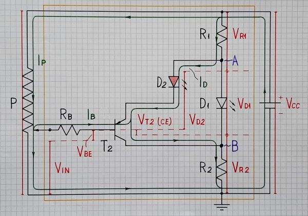
- When the input voltage VIN becomes negative, T2 turns on and connects the red LED D2 in parallel to the green D1. Now, D1 goes out and D2 lights up.
- Fig. 6. The 3-LED voltage indicator at negative input voltage.
- When, two months ago, I accidentally found out about the new Codidact platform, I was happy and decided to take part in it. I wanted to mark this event with an interesting question that would arouse the interest of visitors to the new platform. Thus I remembered an interesting inventive idea from the distant past that then brought me a patent. And I decided to ask a question about it.
- I had two possibilities - to show my possible answer or to wait for others to show their solutions... and I chose the latter. During these two months, my answer matured and I am now sharing it with you.
- To best reveal my idea, I will present it in the form of an inventive scenario of 4 steps.
- In the beginning, imagine we have two LEDs - red (with VF = 1.5 V) and green (VF = 2.5 V), and we want to switch them so that when one is on the other is off and vice versa.
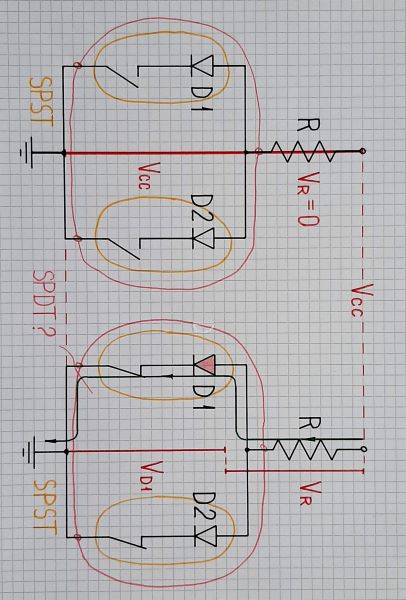
- **1. One SPDT controls two LEDs.** The most obvious solution is to switch the two LEDs with one SPDT switch - Fig. 1.
- 
- Fig. 1. One SPDT controls two LEDs.
- Depending on the switch position, the current is steered between the two LEDs. The voltage drop across them varies between 1.5 V and 2.5 V when we switch them... but so far this does not impress us.
- The problem is that we can not implement an SPDT switch by one BJ transistor since its collector-emitter part acts as a simple 2-terminal SPST switch.
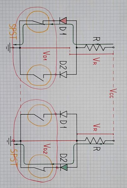
- **2. Two SPST control the LEDs.** But we can assemble an SPDT switch by two SPST switches - Fig. 2, and they can be implemented by transistors.We have to control them so that when one switch is on the other is off and vice versa. Thus there are two valid combinations.
- 
- Fig. 2. Two SPST control the LEDs
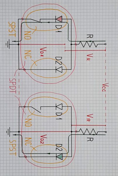
- **3. "Invalid" switch combinations (both off or on).** But with this implementation, two more combinations are possible, in which we may inadvertently fall. First, both switches can be off. Second, which is more interesting, is the combination when both switches are on - Fig. 3.
- 
- Fig. 3. "Invalid" switch combinations (both off or on)
- We expect both LEDs to light up, but to our surprise only the red one lights up. Why?
- The threshold voltage of the red LED is lower than that of the green one. Therefore, when connected in parallel, the current is steered to the red LED. Can not we use this phenomenon to simplify the circuit?
- **4. One SPST controls the LEDs.** Obviously, the right switch is redundant. It does nothing because the LEDs switch themselves. Then let's remove it - Fig. 4. Now the left switch turns on the red LED that, in its turn, turns off the green LED.
- 
- Fig. 4. One SPST controls the two LEDs
- **5. Application.** I have implemented this idea in the circuit of a 3-LED voltage indicator where two transistors control three LEDs. A fragment of this circuit is shown in Fig. 5 in the case the input voltage VIN is positive.
- Initially, the input voltage is zero and the transistor T1 is off. The current flows through the green LED D1 and it is lit. If the voltage becomes positive, T1 turns on and connects the red LED D3 in parallel to the green D1. As a result, D1 goes out and D3 lights up.
- 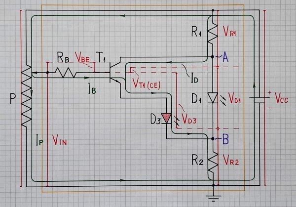
- Fig. 5. The idea is implemented in the circuit of a 3-LED voltage indicator (at positive input voltage).
- When the input voltage VIN becomes negative, T2 turns on and connects the red LED D2 in parallel to the green D1. Now, D1 goes out and D2 lights up.
- 
- Fig. 6. The 3-LED voltage indicator at negative input voltage.
#1: Initial revision
by
Circuit fantasist
·
2020-12-17T16:36:08Z (over 4 years ago)
When, two months ago, I accidentally found out about the new Codidact platform, I was happy and decided to take part in it. I wanted to mark this event with an interesting question that would arouse the interest of visitors to the new platform. Thus I remembered an interesting inventive idea from the distant past that then brought me a patent. And I decided to ask a question about it. I had two possibilities - to show my possible answer or to wait for others to show their solutions... and I chose the latter. During these two months, my answer matured and I am now sharing it with you. To best reveal my idea, I will present it in the form of an inventive scenario of 4 steps. In the beginning, imagine we have two LEDs - red (with VF = 1.5 V) and green (VF = 2.5 V), and we want to switch them so that when one is on the other is off and vice versa. **1. One SPDT controls two LEDs.** The most obvious solution is to switch the two LEDs with one SPDT switch - Fig. 1.  Fig. 1. One SPDT controls two LEDs. Depending on the switch position, the current is steered between the two LEDs. The voltage drop across them varies between 1.5 V and 2.5 V when we switch them... but so far this does not impress us. The problem is that we can not implement an SPDT switch by one BJ transistor since its collector-emitter part acts as a simple 2-terminal SPST switch. **2. Two SPST control the LEDs.** But we can assemble an SPDT switch by two SPST switches - Fig. 2, and they can be implemented by transistors.We have to control them so that when one switch is on the other is off and vice versa. Thus there are two valid combinations.  Fig. 2. Two SPST control the LEDs **3. "Invalid" switch combinations (both off or on).** But with this implementation, two more combinations are possible, in which we may inadvertently fall. First, both switches can be off. Second, which is more interesting, is the combination when both switches are on - Fig. 3.  Fig. 3. "Invalid" switch combinations (both off or on) We expect both LEDs to light up, but to our surprise only the red one lights up. Why? The threshold voltage of the red LED is lower than that of the green one. Therefore, when connected in parallel, the current is steered to the red LED. Can not we use this phenomenon to simplify the circuit? **4. One SPST controls the LEDs.** Obviously, the right switch is redundant. It does nothing because the LEDs switch themselves. Then let's remove it - Fig. 4. Now the left switch turns on the red LED that, in its turn, turns off the green LED.  Fig. 4. One SPST controls the two LEDs **5. Application.** I have implemented this idea in the circuit of a 3-LED voltage indicator where two transistors control three LEDs. A fragment of this circuit is shown in Fig. 5 in the case the input voltage VIN is positive. Initially, the input voltage is zero and the transistor T1 is off. The current flows through the green LED D1 and it is lit. If the voltage becomes positive, T1 turns on and connects the red LED D3 in parallel to the green D1. As a result, D1 goes out and D3 lights up.  Fig. 5. The idea is implemented in the circuit of a 3-LED voltage indicator (at positive input voltage). When the input voltage VIN becomes negative, T2 turns on and connects the red LED D2 in parallel to the green D1. Now, D1 goes out and D2 lights up.  Fig. 6. The 3-LED voltage indicator at negative input voltage.