Post History
I have also had this problem for production runs of 100s to 1000 where you don't want to spend too much on a full fancy jig. Put plain round pads on the bottom of the board. 50 mils is usually a ...
#1: Initial revision
by
 Olin Lathrop
·
2021-01-13T16:54:36Z (over 4 years ago)
Olin Lathrop
·
2021-01-13T16:54:36Z (over 4 years ago)
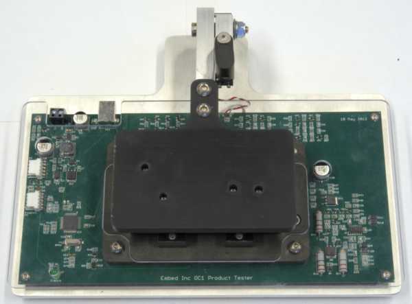
I have also had this problem for production runs of 100s to 1000 where you don't want to spend too much on a full fancy jig. Put plain round pads on the bottom of the board. 50 mils is usually a good diameter. Those work well with simple 90° pogo pins. Don't use holes. In my experience, a pogo pin to hole contact is less reliable than a pogo pin to flat pad contact. Note that if you do use holes for some reason, you have to use pogo pins intended for that. The production jig is the more tricky part. We worked with a mechanical engineer to create a basic design for such jigs for small boards. We design a board that the pogo pin sheaths mount to directly, and they customize the basic design per target board. Since the sheaths solder directly to the tester board, the electrical connections to them are readily available. I usually copy our PIC programmer circuit onto the tester board, along with whatever custom circuitry is needed to testing and calibration. The tester board therefore contains all the electronics of the tester, except maybe the power supply. Sometimes the whole thing can run from just a USB connection. Sometimes we leave binding posts for 24 or 12 V DC external power. You can get all the Eagle devices and packages we use for this from the Eagle Tools software release at http://www.embedinc.com/pic/dload.htm. The pogo pin sheaths and pins are in the POGO library. The attributes give the specific part numbers we use. The pins are separate parts because they have to be ordered and installed separately. The schematic symbols are intended to put a holder and a pin on top of each other. When you do this, you end up with a complete-looking pogo pin in the schematic, and both the holder and pin end up on the BOM. The pogo pin pads for the board under test are in the CONNECTOR library, with names POGO. Use the 50 mil pads on the bottom of the board for most cases. The mechanical arrangement is a base plate that the tester board mounts to. The mechanical engineer designs a custom guide piece that mounts to the top of the board. This guide keeps the pogo pins sticking up from the tester board aligned, and has guides to align and hold the board under test coming down from the top. There is an arm that swings down to hold the board under test in place. The part of the arm touching the board under test is also custom. The arm has a lock to hold the board onto the compressed pogo pins, and a switch connection so that the test circuit knows when the lock is engaged. There is also a custom plexiglass cover mounted above the test board to protect the parts of the board that aren't supposed to be touched. The rest is a bunch of firmware in the tester and software on the host, usually communicating with the tester over USB. Here is what one such tester looks like with the arm open and no UUT in place: 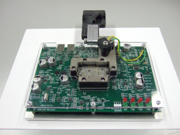 Here is a detail showing the connections to the switch that indicates the arm is locked. You can also see the custom plexiglass piece, and parts on the test board below that. 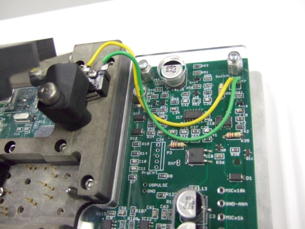 Here is a different tester of this same concept, with the UUT in place. You can also see the USB connector and connection to external DC power at top left. The RED/WHT twisted pair at top center goes to the arm switch. 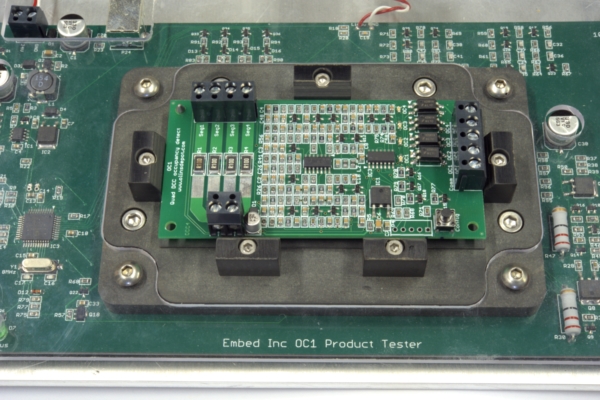 And finally, here is a view with the arm down holding a UUT in place. The arm lock is not engaged.