Post History
Step 1: Since 3V3_ISO would be LDO driven I would probably add a diode with the anode connected to the LDO output and a cathode connected with the LDO input to prevent the LDO to have output high...
#2: Post edited
by
 Lundin
·
2021-02-23T09:40:20Z (over 4 years ago)
Lundin
·
2021-02-23T09:40:20Z (over 4 years ago)
- > Step 1: Since 3V3_ISO would be LDO driven I would probably add a diode with the anode connected to the LDO output and a cathode connected with the LDO input to prevent the LDO to have output higher than the input. Based on my experience they tend not to love that. I haven't post that because I haven't yet designed the power stage.
- Indeed, this is common practice and does help saving the LDO. Normally I'd pick a schottky with high enough reverse voltage, to minimize the voltage difference between LDO input and output. However in this case, 32V is likely far too high input for the LDO (?) depending on type.
- If you have no reason to suspect lots of EMI etc, you shouldn't need galvanic isolation, it makes the BOM expensive. Even with expected EMI, then normally it should suffice with a TVS together with some current limiting resistor, to take the brunt of the load in case some high voltage is applied by accident.
- I'd get rid of the BJT, LDO and optocoupler and just add some protective diodes, one towards ground and one towards the voltage you want. Something like this:
- 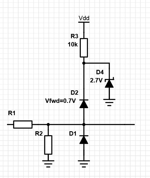
- - TVS optional directly on the input (not drawn).
- - Vdd is some known high voltage you've got access to, like 24VDC.
- R1 is some high ohm >10k.- - R2 optional if you need voltage divider
- - If some high voltage is applied then you lose 0.7V across D2 and the rest across the zener. You end up with ~3.4V that you can safely connect directly to a 3V3 MCU etc.
- > Step 1: Since 3V3_ISO would be LDO driven I would probably add a diode with the anode connected to the LDO output and a cathode connected with the LDO input to prevent the LDO to have output higher than the input. Based on my experience they tend not to love that. I haven't post that because I haven't yet designed the power stage.
- Indeed, this is common practice and does help saving the LDO. Normally I'd pick a schottky with high enough reverse voltage, to minimize the voltage difference between LDO input and output. However in this case, 32V is likely far too high input for the LDO (?) depending on type.
- If you have no reason to suspect lots of EMI etc, you shouldn't need galvanic isolation, it makes the BOM expensive. Even with expected EMI, then normally it should suffice with a TVS together with some current limiting resistor, to take the brunt of the load in case some high voltage is applied by accident.
- I'd get rid of the BJT, LDO and optocoupler and just add some protective diodes, one towards ground and one towards the voltage you want. Something like this:
- 
- - TVS optional directly on the input (not drawn).
- - Vdd is some known high voltage you've got access to, like 24VDC.
- - R1 is some high ohm current limiter >10k.
- - R2 optional if you need voltage divider
- - If some high voltage is applied then you lose 0.7V across D2 and the rest across the zener. You end up with ~3.4V that you can safely connect directly to a 3V3 MCU etc.
#1: Initial revision
by
Lundin
·
2021-02-23T09:39:01Z (over 4 years ago)
> Step 1: Since 3V3_ISO would be LDO driven I would probably add a diode with the anode connected to the LDO output and a cathode connected with the LDO input to prevent the LDO to have output higher than the input. Based on my experience they tend not to love that. I haven't post that because I haven't yet designed the power stage. Indeed, this is common practice and does help saving the LDO. Normally I'd pick a schottky with high enough reverse voltage, to minimize the voltage difference between LDO input and output. However in this case, 32V is likely far too high input for the LDO (?) depending on type. If you have no reason to suspect lots of EMI etc, you shouldn't need galvanic isolation, it makes the BOM expensive. Even with expected EMI, then normally it should suffice with a TVS together with some current limiting resistor, to take the brunt of the load in case some high voltage is applied by accident. I'd get rid of the BJT, LDO and optocoupler and just add some protective diodes, one towards ground and one towards the voltage you want. Something like this:  - TVS optional directly on the input (not drawn). - Vdd is some known high voltage you've got access to, like 24VDC. - R1 is some high ohm >10k. - R2 optional if you need voltage divider - If some high voltage is applied then you lose 0.7V across D2 and the rest across the zener. You end up with ~3.4V that you can safely connect directly to a 3V3 MCU etc.