Post History
Since we are trying to keep the impedance matched to 50 ohms, what is the best strategy to approach this circuit? A low pass $\pi$ network seems a good route to go. Basically your $\pi$ networ...
#7: Post edited
by
 Andy aka
·
2021-03-26T10:57:24Z (about 4 years ago)
Andy aka
·
2021-03-26T10:57:24Z (about 4 years ago)
- > _Since we are trying to keep the impedance matched to 50 ohms, what is the best strategy to approach this circuit?_
A low pass \$\pi\$ network seems a good route to go. Basically a \$\pi\$ can be designed to do two things: -- Impedance match 50 Ω to 50 Ω- - Provide significant attenuation above 900 MHz for the reduction of harmonics.
- The example below matches to 300 Ω but, the calculator allows you to enter both ends as 50 Ω: -
- 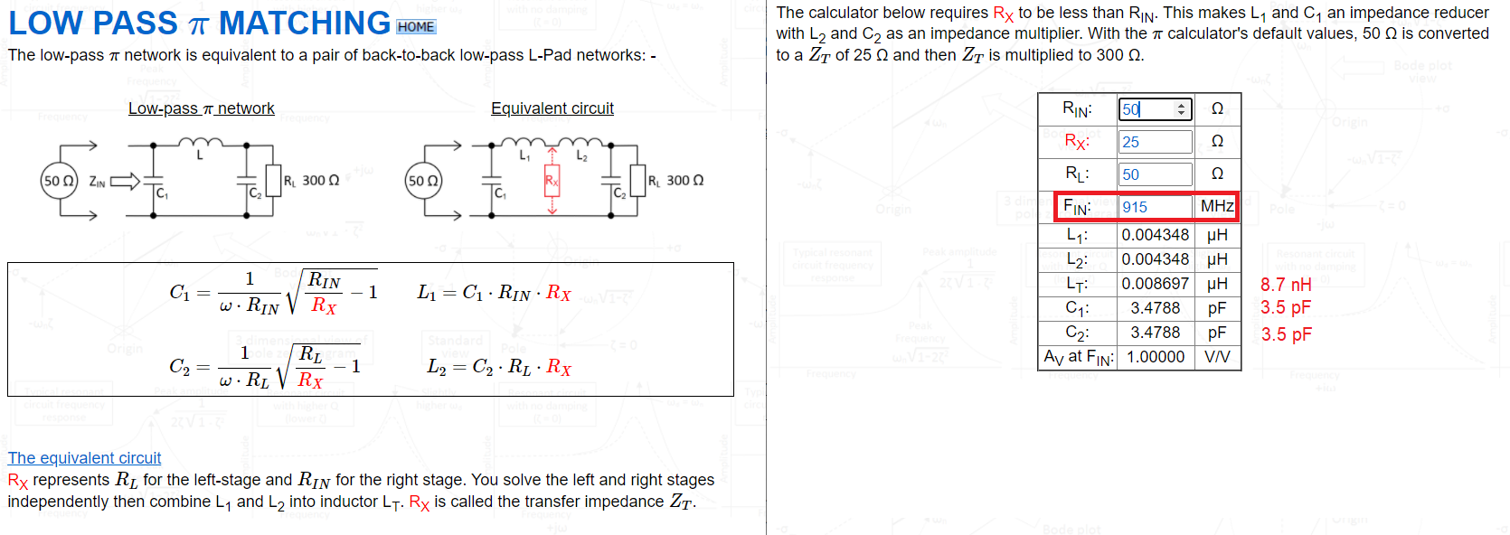
- Picture and calculator can be [found here](http://www.stades.co.uk/Impedance%20TX/Zmatch%20PI%20LP.html).
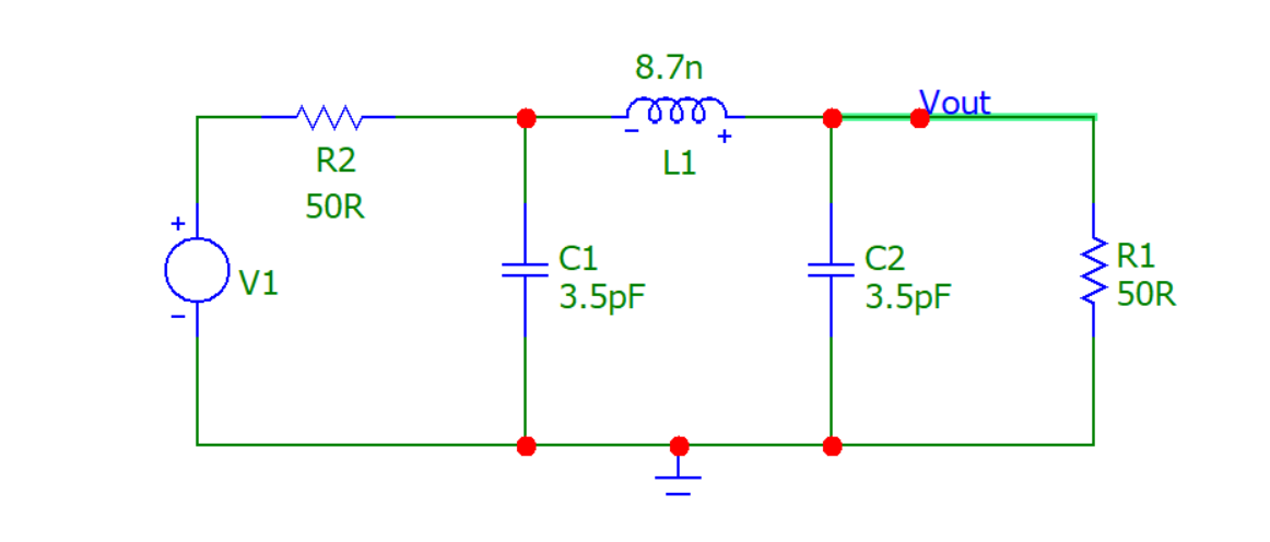
- So, plugging the numbers into a simulator we get this circuit: -
- 
- And we get this AC response: -
- 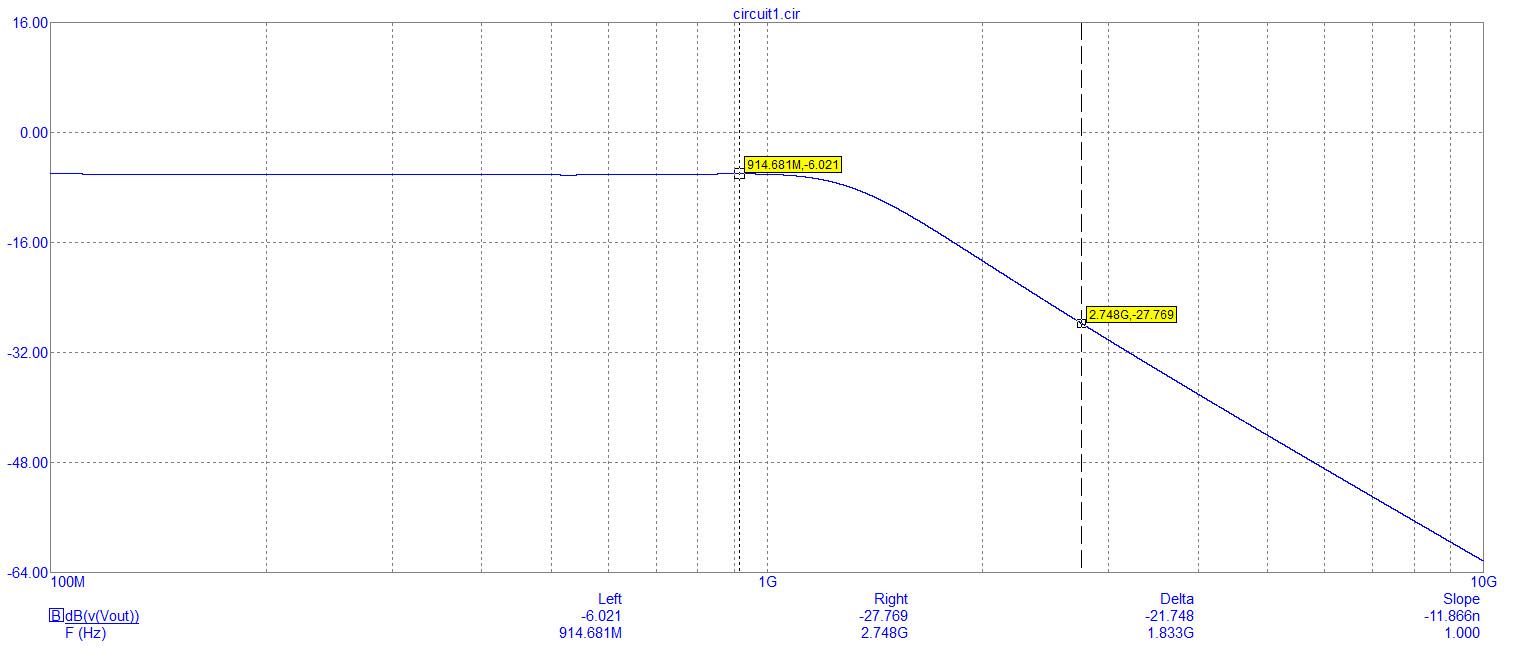
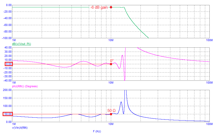
- So, at 915 MHz we get the usual -6.021 dB input to output attenuation when you have matching input and output resistors (50 Ω) and, at the 3rd harmonic of 915 MHz we see an attenuation of 27.7 dB or, a relative attenuation of about 21.5 dB. Clearly that is very significant and, it's going to be even better at the sixth harmonic (around 40 dB I estimate).
- But, remember, that at these frequencies, it's easy to get harmonic leakage to the output with badly chosen inductors and capacitors that are unsuitable for this application so, choose with care. Layout with care also.
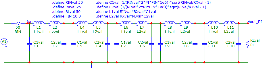
- If you need steeper roll-off above 915 MHz then the beauty about the \$\pi\$ network is that they can be cascaded (because they are impedance matching networks and interactions are minimal). So, here's a five stage example of a \$\pi\$ network schematic (operating at 10 MHz): -
- 
- And here's the frequency response: -
- 
- It's got perfect 50 Ω input and output impedance at 10 MHz and has rolled-off the 2nd harmonic (20 MHz) by around 70 dB.
- > _Since we are trying to keep the impedance matched to 50 ohms, what is the best strategy to approach this circuit?_
- A low pass \$\pi\$ network seems a good route to go. Basically your \$\pi\$ network is designed to do two important things: -
- - Impedance match a 50 Ω source to a 50 Ω load
- - Provide significant attenuation above 900 MHz for the reduction of harmonics.
- The example below matches to 300 Ω but, the calculator allows you to enter both ends as 50 Ω: -
- 
- Picture and calculator can be [found here](http://www.stades.co.uk/Impedance%20TX/Zmatch%20PI%20LP.html).
- So, plugging the numbers into a simulator we get this circuit: -
- 
- And we get this AC response: -
- 
- So, at 915 MHz we get the usual -6.021 dB input to output attenuation when you have matching input and output resistors (50 Ω) and, at the 3rd harmonic of 915 MHz we see an attenuation of 27.7 dB or, a relative attenuation of about 21.5 dB. Clearly that is very significant and, it's going to be even better at the sixth harmonic (around 40 dB I estimate).
- But, remember, that at these frequencies, it's easy to get harmonic leakage to the output with badly chosen inductors and capacitors that are unsuitable for this application so, choose with care. Layout with care also.
- If you need steeper roll-off above 915 MHz then the beauty about the \$\pi\$ network is that they can be cascaded (because they are impedance matching networks and interactions are minimal). So, here's a five stage example of a \$\pi\$ network schematic (operating at 10 MHz): -
- 
- And here's the frequency response: -
- 
- It's got perfect 50 Ω input and output impedance at 10 MHz and has rolled-off the 2nd harmonic (20 MHz) by around 70 dB.
#6: Post edited
by
Andy aka
·
2021-03-25T11:19:21Z (about 4 years ago)
- > _Since we are trying to keep the impedance matched to 50 ohms, what is the best strategy to approach this circuit?_
- A low pass \$\pi\$ network seems a good route to go. Basically a \$\pi\$ can be designed to do two things: -
- - Impedance match 50 Ω to 50 Ω
- - Provide significant attenuation above 900 MHz for the reduction of harmonics.
- The example below matches to 300 Ω but, the calculator allows you to enter both ends as 50 Ω: -
- Picture and calculator can be [found here](http://www.stades.co.uk/Impedance%20TX/Zmatch%20PI%20LP.html).
- So, plugging the numbers into a simulator we get this circuit: -
- And we get this AC response: -
- So, at 915 MHz we get the usual -6.021 dB input to output attenuation when you have matching input and output resistors (50 Ω) and, at the 3rd harmonic of 915 MHz we see an attenuation of 27.7 dB or, a relative attenuation of about 21.5 dB. Clearly that is very significant and, it's going to be even better at the sixth harmonic (around 40 dB I estimate).
- But, remember, that at these frequencies, it's easy to get harmonic leakage to the output with badly chosen inductors and capacitors that are unsuitable for this application so, choose with care. Layout with care also.
- If you need steeper roll-off above 915 MHz then the beauty about the \$\pi\$ network is that they can be cascaded (because they are impedance matching networks and interactions are minimal). So, here's a five stage example of a \$\pi\$ network schematic (operating at 10 MHz): -
- 
- And here's the frequency response: -
- 
- It's got perfect 50 Ω input and output impedance at 10 MHz and has rolled-off the 2nd harmonic (20 MHz) by around 70 dB.
- > _Since we are trying to keep the impedance matched to 50 ohms, what is the best strategy to approach this circuit?_
- A low pass \$\pi\$ network seems a good route to go. Basically a \$\pi\$ can be designed to do two things: -
- - Impedance match 50 Ω to 50 Ω
- - Provide significant attenuation above 900 MHz for the reduction of harmonics.
- The example below matches to 300 Ω but, the calculator allows you to enter both ends as 50 Ω: -
- 
- Picture and calculator can be [found here](http://www.stades.co.uk/Impedance%20TX/Zmatch%20PI%20LP.html).
- So, plugging the numbers into a simulator we get this circuit: -
- 
- And we get this AC response: -
- 
- So, at 915 MHz we get the usual -6.021 dB input to output attenuation when you have matching input and output resistors (50 Ω) and, at the 3rd harmonic of 915 MHz we see an attenuation of 27.7 dB or, a relative attenuation of about 21.5 dB. Clearly that is very significant and, it's going to be even better at the sixth harmonic (around 40 dB I estimate).
- But, remember, that at these frequencies, it's easy to get harmonic leakage to the output with badly chosen inductors and capacitors that are unsuitable for this application so, choose with care. Layout with care also.
- If you need steeper roll-off above 915 MHz then the beauty about the \$\pi\$ network is that they can be cascaded (because they are impedance matching networks and interactions are minimal). So, here's a five stage example of a \$\pi\$ network schematic (operating at 10 MHz): -
- 
- And here's the frequency response: -
- 
- It's got perfect 50 Ω input and output impedance at 10 MHz and has rolled-off the 2nd harmonic (20 MHz) by around 70 dB.
#5: Post edited
by
Andy aka
·
2021-03-25T11:18:13Z (about 4 years ago)
- > _Since we are trying to keep the impedance matched to 50 ohms, what is the best strategy to approach this circuit?_
- A low pass \$\pi\$ network seems a good route to go. Basically a \$\pi\$ can be designed to do two things: -
- - Impedance match 50 Ω to 50 Ω
- - Provide significant attenuation above 900 MHz for the reduction of harmonics.
- The example below matches to 300 Ω but, the calculator allows you to enter both ends as 50 Ω: -
- 
- Picture and calculator can be [found here](http://www.stades.co.uk/Impedance%20TX/Zmatch%20PI%20LP.html).
- So, plugging the numbers into a simulator we get this circuit: -
- 
- And we get this AC response: -
- 
- So, at 915 MHz we get the usual -6.021 dB input to output attenuation when you have matching input and output resistors (50 Ω) and, at the 3rd harmonic of 915 MHz we see an attenuation of 27.7 dB or, a relative attenuation of about 21.5 dB. Clearly that is very significant and, it's going to be even better at the sixth harmonic (around 40 dB I estimate).
But, remember, that at these frequencies, it's easy to get harmonic leakage to the output with badly chosen inductors and capacitors that are unsuitable for this application so, choose with care. Layout with care also.
- > _Since we are trying to keep the impedance matched to 50 ohms, what is the best strategy to approach this circuit?_
- A low pass \$\pi\$ network seems a good route to go. Basically a \$\pi\$ can be designed to do two things: -
- - Impedance match 50 Ω to 50 Ω
- - Provide significant attenuation above 900 MHz for the reduction of harmonics.
- The example below matches to 300 Ω but, the calculator allows you to enter both ends as 50 Ω: -
- 
- Picture and calculator can be [found here](http://www.stades.co.uk/Impedance%20TX/Zmatch%20PI%20LP.html).
- So, plugging the numbers into a simulator we get this circuit: -
- 
- And we get this AC response: -
- 
- So, at 915 MHz we get the usual -6.021 dB input to output attenuation when you have matching input and output resistors (50 Ω) and, at the 3rd harmonic of 915 MHz we see an attenuation of 27.7 dB or, a relative attenuation of about 21.5 dB. Clearly that is very significant and, it's going to be even better at the sixth harmonic (around 40 dB I estimate).
- But, remember, that at these frequencies, it's easy to get harmonic leakage to the output with badly chosen inductors and capacitors that are unsuitable for this application so, choose with care. Layout with care also.
- If you need steeper roll-off above 915 MHz then the beauty about the \$\pi\$ network is that they can be cascaded (because they are impedance matching networks and interactions are minimal). So, here's a five stage example of a \$\pi\$ network schematic (operating at 10 MHz): -
- 
- And here's the frequency response: -
- 
- It's got perfect 50 Ω input and output impedance at 10 MHz and has rolled-off the 2nd harmonic (20 MHz) by around 70 dB.
#4: Post edited
by
Andy aka
·
2021-03-24T13:43:57Z (about 4 years ago)
- > _Since we are trying to keep the impedance matched to 50 ohms, what is the best strategy to approach this circuit?_
- A low pass \$\pi\$ network seems a good route to go. Basically a \$\pi\$ can be designed to do two things: -
- - Impedance match 50 Ω to 50 Ω
- - Provide significant attenuation above 900 MHz for the reduction of harmonics.
- The example below matches to 300 Ω but, the calculator allows you to enter both ends as 50 Ω: -
- 
- Picture and calculator can be [found here](http://www.stades.co.uk/Impedance%20TX/Zmatch%20PI%20LP.html).
- So, plugging the numbers into a simulator we get this circuit: -
- 
- And we get this AC response: -
- 
So, at 915 MHz we get the usual -6.021 dB input to output attenuation when you have matching input and output resistors (50 Ω) and, at the 3rd harmonic of 915 MHz we seen an attenuation of 27.7 dB or, a relative attenuation of about 21.5 dB. Clearly that is significant and, it's going to be even better at the sixth harmonic (around 40 dB).But, remember that at these frequencies it's easy to get harmonic leakage to the output with badly chosen inductors and capacitors that are unsuitable for this application so, choose with care.
- > _Since we are trying to keep the impedance matched to 50 ohms, what is the best strategy to approach this circuit?_
- A low pass \$\pi\$ network seems a good route to go. Basically a \$\pi\$ can be designed to do two things: -
- - Impedance match 50 Ω to 50 Ω
- - Provide significant attenuation above 900 MHz for the reduction of harmonics.
- The example below matches to 300 Ω but, the calculator allows you to enter both ends as 50 Ω: -
- 
- Picture and calculator can be [found here](http://www.stades.co.uk/Impedance%20TX/Zmatch%20PI%20LP.html).
- So, plugging the numbers into a simulator we get this circuit: -
- 
- And we get this AC response: -
- 
- So, at 915 MHz we get the usual -6.021 dB input to output attenuation when you have matching input and output resistors (50 Ω) and, at the 3rd harmonic of 915 MHz we see an attenuation of 27.7 dB or, a relative attenuation of about 21.5 dB. Clearly that is very significant and, it's going to be even better at the sixth harmonic (around 40 dB I estimate).
- But, remember, that at these frequencies, it's easy to get harmonic leakage to the output with badly chosen inductors and capacitors that are unsuitable for this application so, choose with care. Layout with care also.
#3: Post edited
by
Andy aka
·
2021-03-24T13:42:02Z (about 4 years ago)
- > _Since we are trying to keep the impedance matched to 50 ohms, what is the best strategy to approach this circuit?_
- A low pass \$\pi\$ network seems a good route to go. Basically a \$\pi\$ can be designed to do two things: -
- - Impedance match 50 Ω to 50 Ω
- - Provide significant attenuation above 900 MHz for the reduction of harmonics.
- The example below matches to 300 Ω but, the calculator allows you to enter both ends as 50 Ω: -
- 
- Picture and calculator can be [found here](http://www.stades.co.uk/Impedance%20TX/Zmatch%20PI%20LP.html).
- So, plugging the numbers into a simulator we get this circuit: -
- 
- And we get this AC response: -
- 
So, at 915 MHz we get the usual -6.021 dB input to output attenuation when you have matching input and output resistors (50 Ω) and, at the 3rd harmonic of 915 MHz we seen an attenuation of 27.7 dB or, a relative attenuation of about 21.5 dB. Clearly that is significant and, it's going to be even better at the sixth harmonic.
- > _Since we are trying to keep the impedance matched to 50 ohms, what is the best strategy to approach this circuit?_
- A low pass \$\pi\$ network seems a good route to go. Basically a \$\pi\$ can be designed to do two things: -
- - Impedance match 50 Ω to 50 Ω
- - Provide significant attenuation above 900 MHz for the reduction of harmonics.
- The example below matches to 300 Ω but, the calculator allows you to enter both ends as 50 Ω: -
- 
- Picture and calculator can be [found here](http://www.stades.co.uk/Impedance%20TX/Zmatch%20PI%20LP.html).
- So, plugging the numbers into a simulator we get this circuit: -
- 
- And we get this AC response: -
- 
- So, at 915 MHz we get the usual -6.021 dB input to output attenuation when you have matching input and output resistors (50 Ω) and, at the 3rd harmonic of 915 MHz we seen an attenuation of 27.7 dB or, a relative attenuation of about 21.5 dB. Clearly that is significant and, it's going to be even better at the sixth harmonic (around 40 dB).
- But, remember that at these frequencies it's easy to get harmonic leakage to the output with badly chosen inductors and capacitors that are unsuitable for this application so, choose with care.
#2: Post edited
by
Andy aka
·
2021-03-24T13:39:22Z (about 4 years ago)
- > _Since we are trying to keep the impedance matched to 50 ohms, what is the best strategy to approach this circuit?_
- A low pass \$\pi\$ network seems a good route to go. Basically a \$\pi\$ can be designed to do two things: -
- - Impedance match 50 Ω to 50 Ω
- - Provide significant attenuation above 900 MHz for the reduction of harmonics.
- The example below matches to 300 Ω but, the calculator allows you to enter both ends as 50 Ω: -
- 
Picture and calculator can be [found here](http://www.stades.co.uk/Impedance%20TX/Zmatch%20PI%20LP.html).
- > _Since we are trying to keep the impedance matched to 50 ohms, what is the best strategy to approach this circuit?_
- A low pass \$\pi\$ network seems a good route to go. Basically a \$\pi\$ can be designed to do two things: -
- - Impedance match 50 Ω to 50 Ω
- - Provide significant attenuation above 900 MHz for the reduction of harmonics.
- The example below matches to 300 Ω but, the calculator allows you to enter both ends as 50 Ω: -
- 
- Picture and calculator can be [found here](http://www.stades.co.uk/Impedance%20TX/Zmatch%20PI%20LP.html).
- So, plugging the numbers into a simulator we get this circuit: -
- 
- And we get this AC response: -
- 
- So, at 915 MHz we get the usual -6.021 dB input to output attenuation when you have matching input and output resistors (50 Ω) and, at the 3rd harmonic of 915 MHz we seen an attenuation of 27.7 dB or, a relative attenuation of about 21.5 dB. Clearly that is significant and, it's going to be even better at the sixth harmonic.
#1: Initial revision
by
Andy aka
·
2021-03-24T13:29:27Z (about 4 years ago)
> _Since we are trying to keep the impedance matched to 50 ohms, what is the best strategy to approach this circuit?_ A low pass \$\pi\$ network seems a good route to go. Basically a \$\pi\$ can be designed to do two things: - - Impedance match 50 Ω to 50 Ω - Provide significant attenuation above 900 MHz for the reduction of harmonics. The example below matches to 300 Ω but, the calculator allows you to enter both ends as 50 Ω: -  Picture and calculator can be [found here](http://www.stades.co.uk/Impedance%20TX/Zmatch%20PI%20LP.html).