Post History
To answer some of your questions: Cable inductance: approx 1uH/m +/-50% depends slightly on l/d ratio , while cable impedance from sqrt(L/C) depends on twists/ft 50pF/m while coax is ~100pF/m ...
#3: Post edited
by
 TonyStewart
·
2021-05-04T20:36:00Z (about 4 years ago)
TonyStewart
·
2021-05-04T20:36:00Z (about 4 years ago)
- FWIW this is just anecdotal experience of modifying a variable AC/DC 100W 3ph 74Vdc fan powered by 120Vac.
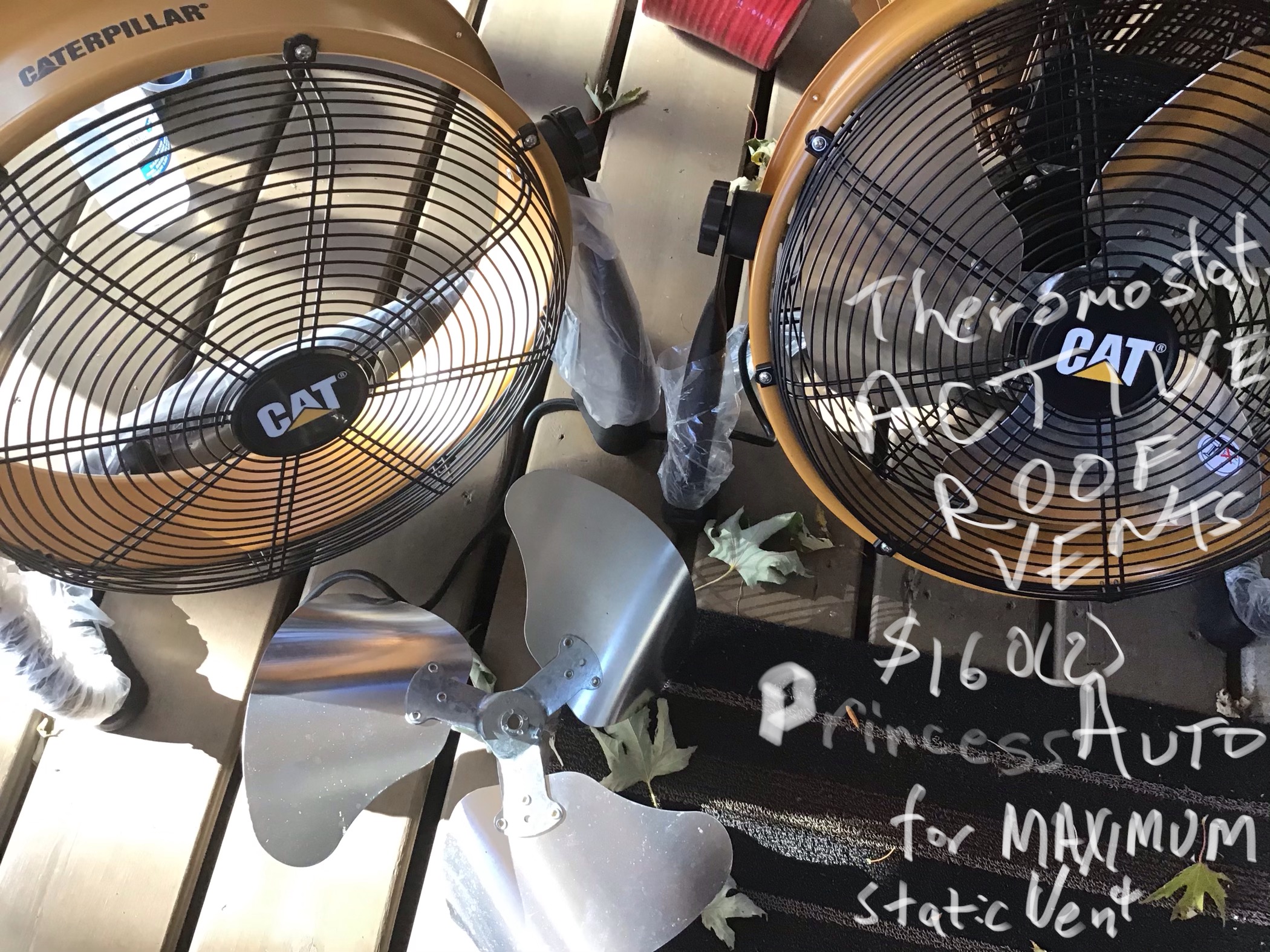
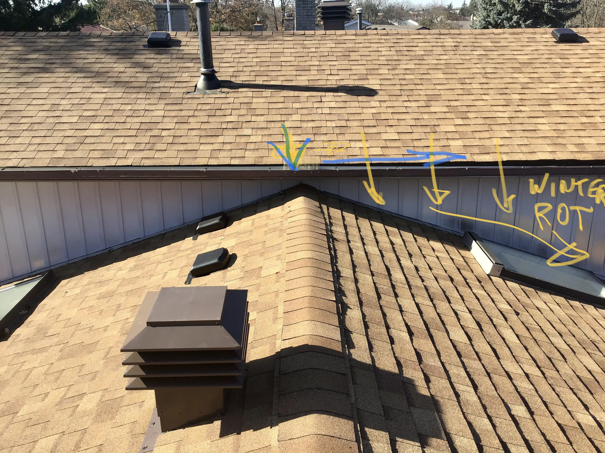
- Last year I modified a 5000 CFM 3-phase 100W fan to operate in the reverse direction and installed in my attic just under the chimney type static roof vent for removing solar heat effects on a 3 ton Air conditioner in hot summer days in a older mid 80’s house with inadequate insulation. I added >R50 blown fibreglass 16 to 24” deep and it did’t help. The problem was the static vents couldn’t remove the hot air fast enough and the Whirleybird vent didn’t move on a calm hot day.
- Background
- The solution required me to reverse-engineer the STM uC control of the drivers and Hall sensors and ended up bringing out the variable speed control voltage and 5V, 0V and a temp sensor on Cat5 cable along with the 120V Ac cord for remote control of attic temp. One only had to choose the right pair to swap of 3 Hall sensors with any select pair swapped of the 3ph motor lines. Then reshape the 3 blades for a reverse angle and then I could strip the casing and insert it to pull air out of the roof vent , rather than push without a means to attach it to the static vent. It was a challenge to get the 14” fan to fit inside the 12” square roof hole , it worked like a charm, quiet, but powerful like a cyclone. ( at least pulling the volume of insulation reduced volume of air every second or so.)
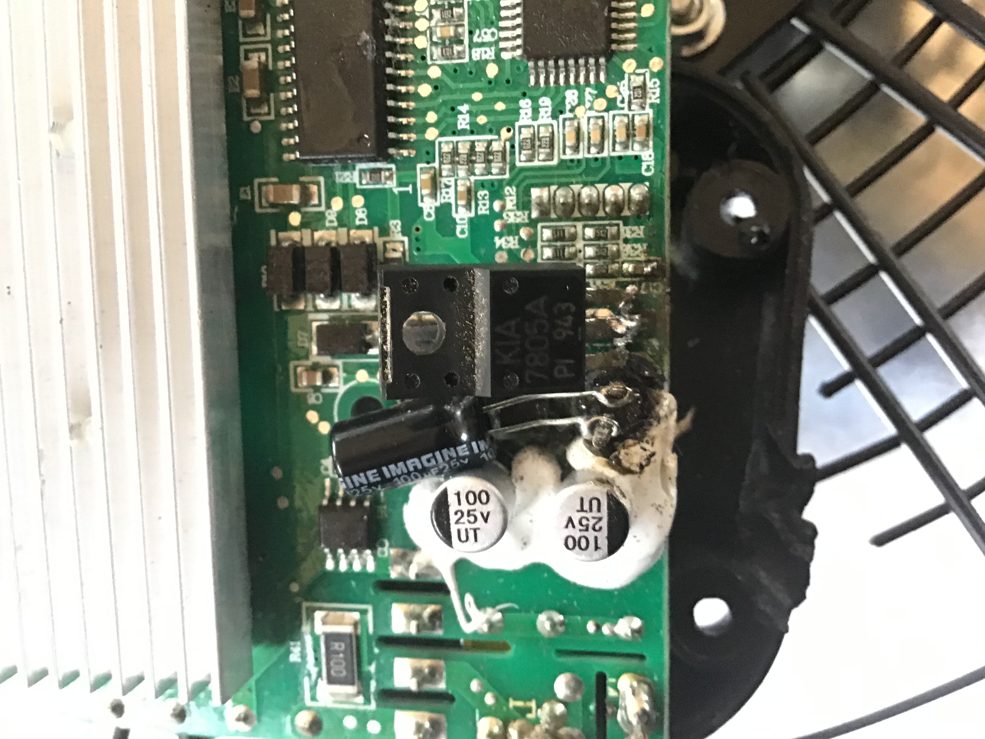
- They used a non-isolated AC to DC-DC converter to -74V w.r.t. gnd so 5V was actually -69V and 0V for some logic was -74V.
- e-Caps
- -
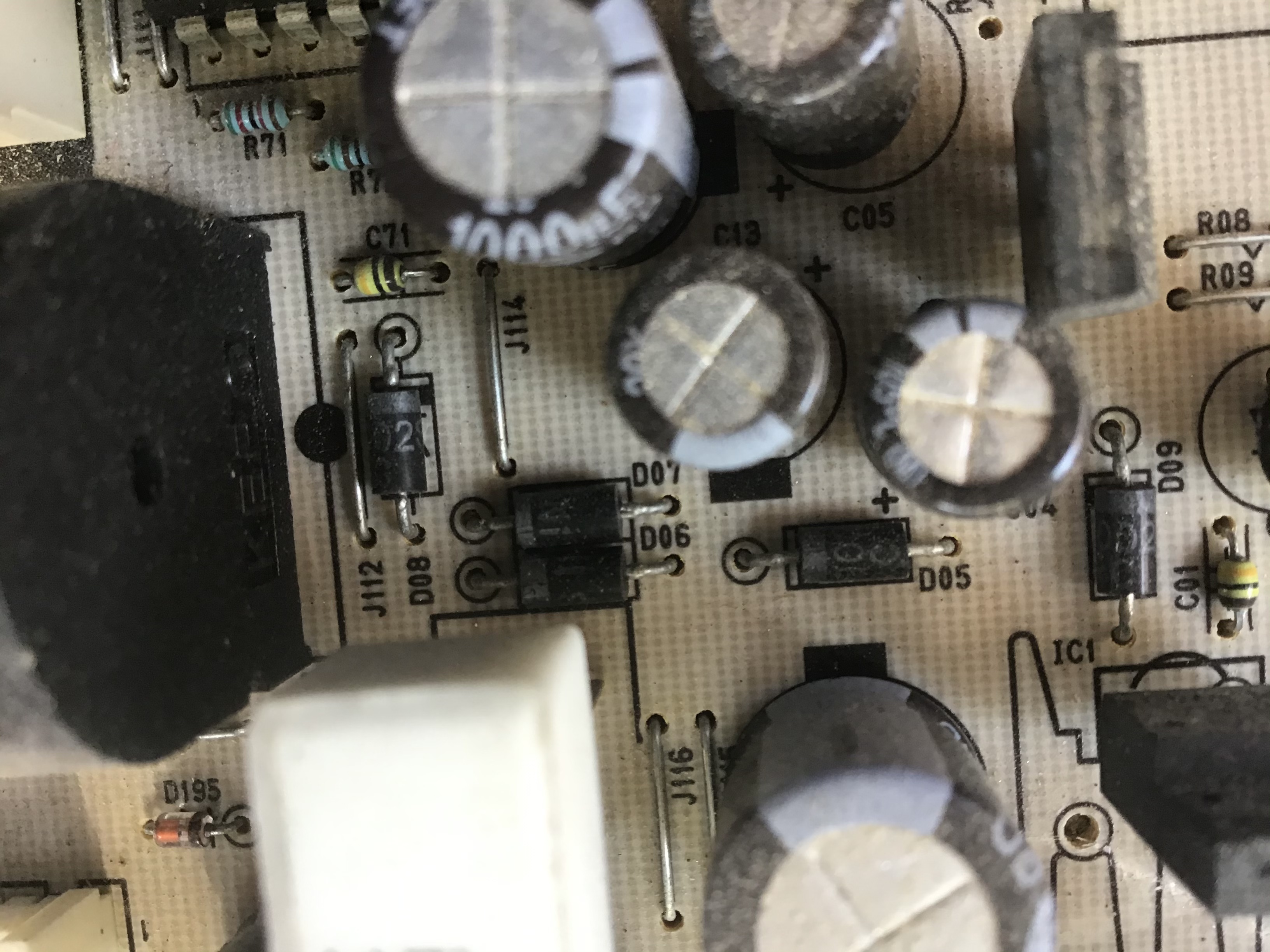
- They did use Nichicon bulk caps to rectify the line but I don’t have the p/n’s. They were used to rectify Ac and smooth the DCDC bulk output ripple with ~1.4A DC and low ripple voltage. I estimate ripple current was low in this case but ESRxC is <10us for low ESR types and ~150 us for standard e-caps.
- The STM uC used the pot voltage 0 to 5V to control the 3 phase sine waves PWM modulated and a V/f transfer function with a slew-rate controlled fan speed so the peak current starting never exceeding rated current for 100W unlike a full start that would take 1kW. This made the power source matched to the load and made it extremely efficient and quiet ramping up in a couple seconds. The FET array was heatsink and of course forced air cooled.;) but never got warm .
- 
- 
- 
- 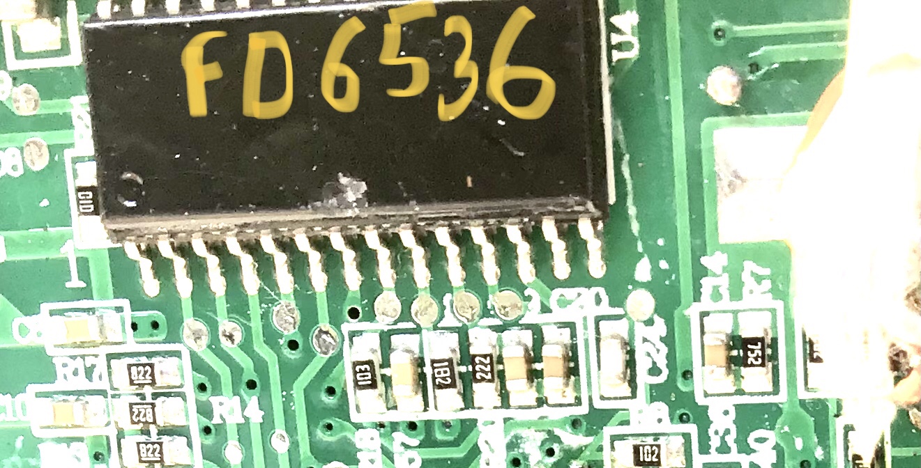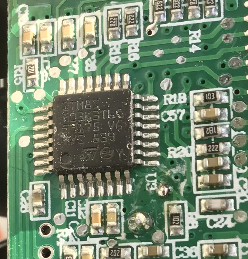
- I don’t have the partial schematic handy or the cap p/n’s but could get if nec. They tried to sand off all the critical p/n’s on ICs but I could still read them to figure out how it worked.
- .
- To answer some of your questions:
- Cable inductance:
- -
- - approx 1uH/m +/-50% depends slightly on l/d ratio , while cable impedance from sqrt(L/C) depends on twists/ft 50pF/m while coax is ~100pF/m
- Bulk storage Cap
- -
- - C value should store Energy Ec for load power x sag time between pulses with the ripple current rating spec derated >50% or ESR computed for same with ripple voltage spec and heat loss or D.F. @ f Thus compute Ec max x Ec min for ripple voltage max,min. to provide power between PWM pulses.
- - For AC the peak/avg current ratio is the inverse of % voltage ripple , i.e. 10% V ripple means about 10x peak current to sustain average load current max.
- - For very low ripple or very high current, multi-phase PWM converters are used.
- Anecdotal
- ==========
- FWIW this is just anecdotal experience of modifying a variable AC/DC 100W 3ph 74Vdc fan powered by 120Vac.
- —————————————-
- Last year I modified a 5000 CFM 3-phase 100W fan to operate in the reverse direction and installed in my attic just under the chimney type static roof vent for removing solar heat effects on a 3 ton Air conditioner in hot summer days in a older mid 80’s house with inadequate insulation. I added >R50 blown fibreglass 16 to 24” deep and it did’t help. The problem was the static vents couldn’t remove the hot air fast enough and the Whirleybird vent didn’t move on a calm hot day.
- Background
- The solution required me to reverse-engineer the STM uC control of the drivers and Hall sensors and ended up bringing out the variable speed control voltage and 5V, 0V and a temp sensor on Cat5 cable along with the 120V Ac cord for remote control of attic temp. One only had to choose the right pair to swap of 3 Hall sensors with any select pair swapped of the 3ph motor lines. Then reshape the 3 blades for a reverse angle and then I could strip the casing and insert it to pull air out of the roof vent , rather than push without a means to attach it to the static vent. It was a challenge to get the 14” fan to fit inside the 12” square roof hole , it worked like a charm, quiet, but powerful like a cyclone. ( at least pulling the volume of insulation reduced volume of air every second or so.)
- They used a non-isolated AC to DC-DC converter to -74V w.r.t. gnd so 5V was actually -69V and 0V for some logic was -74V.
- e-Caps
- -
- They did use Nichicon bulk caps to rectify the line but I don’t have the p/n’s. They were used to rectify Ac and smooth the DCDC bulk output ripple with ~1.4A DC and low ripple voltage. I estimate ripple current was low in this case but ESRxC is <10us for low ESR types and ~150 us for standard e-caps.
- The STM uC used the pot voltage 0 to 5V to control the 3 phase sine waves PWM modulated and a V/f transfer function with a slew-rate controlled fan speed so the peak current starting never exceeding rated current for 100W unlike a full start that would take 1kW. This made the power source matched to the load and made it extremely efficient and quiet ramping up in a couple seconds. The FET array was heatsink and of course forced air cooled.;) but never got warm .
- 
- 
- 
- 
- I don’t have the partial schematic handy or the cap p/n’s but could get if nec. They tried to sand off all the critical p/n’s on ICs but I could still read them to figure out how it worked.
- .
#2: Post edited
by
TonyStewart
·
2021-05-04T19:29:49Z (about 4 years ago)
- FWIW this is just anecdotal experience of modifying a variable AC/DC 100W 3ph 74Vdc fan powered by 120Vac.
Last year I modified a 5000 CFM 3-phase 100W fan to operate in the reverse direction and installed in my attic just under the chimney type static roof vent for removing solar heat effects on a 3 ton Air conditioner in hot summer days in a older mid 80’s noise with inadequate insulation. I added >R50 blown fibreglass 16 to 24” deep and it did’t help. The problem was the static vents couldn’t remove the hot air fast enough and the Whirleybird vent didn’t move on a calm hot day.- Background
- The solution required me to reverse-engineer the STM uC control of the drivers and Hall sensors and ended up bringing out the variable speed control voltage and 5V, 0V and a temp sensor on Cat5 cable along with the 120V Ac cord for remote control of attic temp. One only had to choose the right pair to swap of 3 Hall sensors with any select pair swapped of the 3ph motor lines. Then reshape the 3 blades for a reverse angle and then I could strip the casing and insert it to pull air out of the roof vent , rather than push without a means to attach it to the static vent. It was a challenge to get the 14” fan to fit inside the 12” square roof hole , it worked like a charm, quiet, but powerful like a cyclone. ( at least pulling the volume of insulation reduced volume of air every second or so.)
- They used a non-isolated AC to DC-DC converter to -74V w.r.t. gnd so 5V was actually -69V and 0V for some logic was -74V.
- e-Caps
- -
- They did use Nichicon bulk caps to rectify the line but I don’t have the p/n’s. They were used to rectify Ac and smooth the DCDC bulk output ripple with ~1.4A DC and low ripple voltage. I estimate ripple current was low in this case but ESRxC is <10us for low ESR types and ~150 us for standard e-caps.
- The STM uC used the pot voltage 0 to 5V to control the 3 phase sine waves PWM modulated and a V/f transfer function with a slew-rate controlled fan speed so the peak current starting never exceeding rated current for 100W unlike a full start that would take 1kW. This made the power source matched to the load and made it extremely efficient and quiet ramping up in a couple seconds. The FET array was heatsink and of course forced air cooled.;) but never got warm .
- 
- 
- 
- 
- I don’t have the partial schematic handy or the cap p/n’s but could get if nec. They tried to sand off all the critical p/n’s on ICs but I could still read them to figure out how it worked.
- .
- FWIW this is just anecdotal experience of modifying a variable AC/DC 100W 3ph 74Vdc fan powered by 120Vac.
- Last year I modified a 5000 CFM 3-phase 100W fan to operate in the reverse direction and installed in my attic just under the chimney type static roof vent for removing solar heat effects on a 3 ton Air conditioner in hot summer days in a older mid 80’s house with inadequate insulation. I added >R50 blown fibreglass 16 to 24” deep and it did’t help. The problem was the static vents couldn’t remove the hot air fast enough and the Whirleybird vent didn’t move on a calm hot day.
- Background
- The solution required me to reverse-engineer the STM uC control of the drivers and Hall sensors and ended up bringing out the variable speed control voltage and 5V, 0V and a temp sensor on Cat5 cable along with the 120V Ac cord for remote control of attic temp. One only had to choose the right pair to swap of 3 Hall sensors with any select pair swapped of the 3ph motor lines. Then reshape the 3 blades for a reverse angle and then I could strip the casing and insert it to pull air out of the roof vent , rather than push without a means to attach it to the static vent. It was a challenge to get the 14” fan to fit inside the 12” square roof hole , it worked like a charm, quiet, but powerful like a cyclone. ( at least pulling the volume of insulation reduced volume of air every second or so.)
- They used a non-isolated AC to DC-DC converter to -74V w.r.t. gnd so 5V was actually -69V and 0V for some logic was -74V.
- e-Caps
- -
- They did use Nichicon bulk caps to rectify the line but I don’t have the p/n’s. They were used to rectify Ac and smooth the DCDC bulk output ripple with ~1.4A DC and low ripple voltage. I estimate ripple current was low in this case but ESRxC is <10us for low ESR types and ~150 us for standard e-caps.
- The STM uC used the pot voltage 0 to 5V to control the 3 phase sine waves PWM modulated and a V/f transfer function with a slew-rate controlled fan speed so the peak current starting never exceeding rated current for 100W unlike a full start that would take 1kW. This made the power source matched to the load and made it extremely efficient and quiet ramping up in a couple seconds. The FET array was heatsink and of course forced air cooled.;) but never got warm .
- 
- 
- 
- 
- I don’t have the partial schematic handy or the cap p/n’s but could get if nec. They tried to sand off all the critical p/n’s on ICs but I could still read them to figure out how it worked.
- .
#1: Initial revision
by
TonyStewart
·
2021-05-04T19:26:31Z (about 4 years ago)
FWIW this is just anecdotal experience of modifying a variable AC/DC 100W 3ph 74Vdc fan powered by 120Vac. Last year I modified a 5000 CFM 3-phase 100W fan to operate in the reverse direction and installed in my attic just under the chimney type static roof vent for removing solar heat effects on a 3 ton Air conditioner in hot summer days in a older mid 80’s noise with inadequate insulation. I added >R50 blown fibreglass 16 to 24” deep and it did’t help. The problem was the static vents couldn’t remove the hot air fast enough and the Whirleybird vent didn’t move on a calm hot day. Background The solution required me to reverse-engineer the STM uC control of the drivers and Hall sensors and ended up bringing out the variable speed control voltage and 5V, 0V and a temp sensor on Cat5 cable along with the 120V Ac cord for remote control of attic temp. One only had to choose the right pair to swap of 3 Hall sensors with any select pair swapped of the 3ph motor lines. Then reshape the 3 blades for a reverse angle and then I could strip the casing and insert it to pull air out of the roof vent , rather than push without a means to attach it to the static vent. It was a challenge to get the 14” fan to fit inside the 12” square roof hole , it worked like a charm, quiet, but powerful like a cyclone. ( at least pulling the volume of insulation reduced volume of air every second or so.) They used a non-isolated AC to DC-DC converter to -74V w.r.t. gnd so 5V was actually -69V and 0V for some logic was -74V. e-Caps - They did use Nichicon bulk caps to rectify the line but I don’t have the p/n’s. They were used to rectify Ac and smooth the DCDC bulk output ripple with ~1.4A DC and low ripple voltage. I estimate ripple current was low in this case but ESRxC is <10us for low ESR types and ~150 us for standard e-caps. The STM uC used the pot voltage 0 to 5V to control the 3 phase sine waves PWM modulated and a V/f transfer function with a slew-rate controlled fan speed so the peak current starting never exceeding rated current for 100W unlike a full start that would take 1kW. This made the power source matched to the load and made it extremely efficient and quiet ramping up in a couple seconds. The FET array was heatsink and of course forced air cooled.;) but never got warm .     I don’t have the partial schematic handy or the cap p/n’s but could get if nec. They tried to sand off all the critical p/n’s on ICs but I could still read them to figure out how it worked. .