Post History
I'll try first to give a general introduction to the problem, then I'll switch to your particular questions. Passive linear components, like capacitors, inductors or resistors are not ideal. For t...
#3: Post edited
by
 coquelicot
·
2021-05-10T05:18:19Z (about 4 years ago)
coquelicot
·
2021-05-10T05:18:19Z (about 4 years ago)
- I'll try first to give a general introduction to the problem, then I'll switch to your particular questions.
- Passive linear components, like capacitors, inductors or resistors are not ideal. For this reason, they are often modeled electrically as a more or less complex circuit involving resistances, capacitances and inductances. For example, a capacitor is often modeled as a capacitor in series with a resistor (the so called ESR) and an inductor (the so called ESL).
- But even this model fails to represent the electrical behavior of the capacitor at very high frequencies, and must be refined to this end.
- The same could be said about resistors, inductors etc.
- Dealing with complex electrical models would be difficult, but fortunately, there is a much simpler way to understand the behavior of these passive components: the notion of complex impedance (I assume you know it, otherwise, you may want to try [this Wikipedia article](https://en.wikipedia.org/wiki/Electrical_impedance)).
- So, at a given frequency $f$, you have
- $$ V = Z I,$$
- Where $Z$ is the complex impedance of the component at frequency $f$, $V$ is the complex voltage, and $I$ is the complex current.
- As a complex number, $Z$ can be written
- $$ Z = a + j b, $$
- with $a$ and $b$ real. For passive components, $a$ is always positive and represents a resistance.
- On the other hand, $b$ may be positive or negative: if it is positive, that means that the component exhibits an "inductive" behavior at this frequency; if it is negative, it exhibits a "capacitive" behavior.
- That's because the complex impedance of an ideal inductor is
- $$Z = jb = 2 \pi f L \cdot j, $$ (hence $b>0$) and that of an ideal capacitor is $$Z = jb = -{1\over 2 \pi f C} j$$ (hence $b<0$).
- At this point, I would like to formulate the following remarks:
- * As we've just seen, the "good" way to understand passive linear components is through their complex impedance: don't think too much about capacitance, inductance, dielectric loss etc. (unless, of course, you have good reasons to do so). The real point is that at a given frequency, you have something that **exhibits** an inductive or capacitive behavior, in addition to its resistance.
- * All what have been said concerns a particular frequency $f$, but as the frequency $f$ varies, the behavior of the components varies as well: at some frequencies, the component may exhibit a capacitive behavior. At another higher frequency, it may exhibit an inductive behavior etc. (more about that below).
- Mathematically, you have
- $$Z = Z(f).$$
- * At DC (the limit case where $f = 0$), the component is nearly ideal (usually at a very high degree of accuracy): a capacitor is an open circuit, and an inductor is a short. Since this is always the case, this need not be dealt in the datasheet: only the AC behavior is interesting.
- * It should also be added that there are dedicated instruments that allow measuring the complex impedance of components as a function of the frequency: the so-called network analyzers, and especially vector network analyzers (VNA). Usually, there is a whole accompanying theory of S_ij parameters, equivalent to the complex impedance theory, but that's another story.
- After this introduction, let examine your graphs:
- 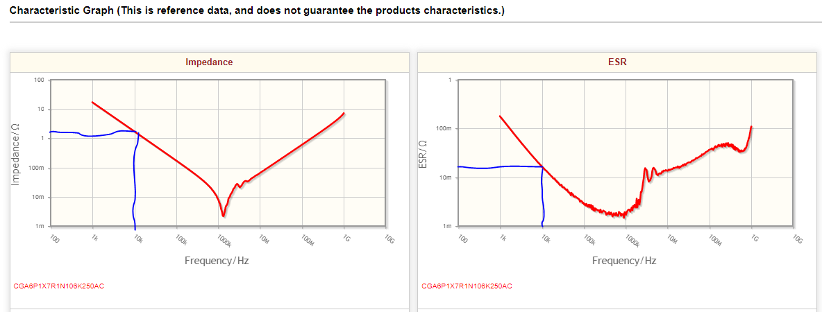
- The first graph is a typical capacitor graph:
- It does not tell you what is the complex impedance $Z = Z(f)$ of the cap, but only its module $|Z(f)|$, which has also the dimension of "Ohm".
- With some experience, you are supposed to identify the shape of this graph, and to understand that the cap exhibits a capacitive behavior up to a bit more than 1000kHz, where it becomes purely resistive. From this point and up to 1GHz, the component exhibits an inductive behavior.
- So, half graph is capacitive, and the second half is inductive. But how much is each half capacitive/inductive? That's where the second graph comes into play.
- Recall that you have $Z = a + jb$, where $a = ESR$ (given in the second graph).
- The first graph gives you $|Z| = \sqrt{a^2 + b^2}$, hence, with some math, you have
- $$|b| = \sqrt{|Z|^2 - a^2}.$$
- More practically, at 10kHz, you see that the first graph gives you an impedance $|Z| = 1\Omega$, while the second graph gives you $a = 20 m\Omega$ (say). Since $1 \Omega$ is much larger than $20m\Omega$, you see that quantity $b$ dominates widely. In other words, at 10kHz, there is a very small ESR resistance (compared to the capacitive reactance), hence you have something that behaves almost like an ideal capacitor. Near 100kHz, the behavior is still widely capacitive. But the more you approach the resonance frequency, the more the component becomes resistive and the less it behaves like a capacitor. At the resonance frequency (about 1MHz) it is purely resistive. After the resonance, it becomes more and more inductive (and the way to compute the ESL is the same as previously). This continues up to 1 GHz or more. Then, if the graph had been continued, it would be observed that the component becomes again capacitive.
- **A final note**: you may ask yourselves what to do if capacitors become inductive above the resonance frequency; Indeed, I've tested many ceramic capacitors with a VNA and have observed that most of them have their resonance point below 50MHz, not so high a frequency!
- Well, the truth is that in general, who care? most often, you use a cap to eliminate the DC component in a signal and pass only the AC component. From this point of view, the capacitor does always its work, no matter if it becomes an inductor at high frequencies or not. Since in most applications, you deal only with a given frequency in the signal, the only thing that matters is the absolute value of the impedance $|Z|$.
Of course, if you are designing an application that is supposed to preserve the AC component of a signal in an ultra wide band (like an oscilloscope), that's another story. Fortunately, we usually leave this task to great masters and gurus in electronics :-)
- I'll try first to give a general introduction to the problem, then I'll switch to your particular questions.
- Passive linear components, like capacitors, inductors or resistors are not ideal. For this reason, they are often modeled electrically as a more or less complex circuit involving resistances, capacitances and inductances. For example, a capacitor is often modeled as a capacitor in series with a resistor (the so called ESR) and an inductor (the so called ESL).
- But even this model fails to represent the electrical behavior of the capacitor at very high frequencies, and must be refined to this end.
- The same could be said about resistors, inductors etc.
- Dealing with complex electrical models would be difficult, but fortunately, there is a much simpler way to understand the behavior of these passive components: the notion of complex impedance (I assume you know it, otherwise, you may want to try [this Wikipedia article](https://en.wikipedia.org/wiki/Electrical_impedance)).
- So, at a given frequency $f$, you have
- $$ V = Z I,$$
- Where $Z$ is the complex impedance of the component at frequency $f$, $V$ is the complex voltage, and $I$ is the complex current.
- As a complex number, $Z$ can be written
- $$ Z = a + j b, $$
- with $a$ and $b$ real. For passive components, $a$ is always positive and represents a resistance.
- On the other hand, $b$ may be positive or negative: if it is positive, that means that the component exhibits an "inductive" behavior at this frequency; if it is negative, it exhibits a "capacitive" behavior.
- That's because the complex impedance of an ideal inductor is
- $$Z = jb = 2 \pi f L \cdot j, $$ (hence $b>0$) and that of an ideal capacitor is $$Z = jb = -{1\over 2 \pi f C} j$$ (hence $b<0$).
- At this point, I would like to formulate the following remarks:
- * As we've just seen, the "good" way to understand passive linear components is through their complex impedance: don't think too much about capacitance, inductance, dielectric loss etc. (unless, of course, you have good reasons to do so). The real point is that at a given frequency, you have something that **exhibits** an inductive or capacitive behavior, in addition to its resistance.
- * All what have been said concerns a particular frequency $f$, but as the frequency $f$ varies, the behavior of the components varies as well: at some frequencies, the component may exhibit a capacitive behavior. At another higher frequency, it may exhibit an inductive behavior etc. (more about that below).
- Mathematically, you have
- $$Z = Z(f).$$
- * At DC (the limit case where $f = 0$), the component is nearly ideal (usually at a very high degree of accuracy): a capacitor is an open circuit, and an inductor is a short. Since this is always the case, this need not be dealt in the datasheet: only the AC behavior is interesting.
- * It should also be added that there are dedicated instruments that allow measuring the complex impedance of components as a function of the frequency: the so-called network analyzers, and especially vector network analyzers (VNA). Usually, there is a whole accompanying theory of S_ij parameters, equivalent to the complex impedance theory, but that's another story.
- After this introduction, let examine your graphs:
- 
- The first graph is a typical capacitor graph:
- It does not tell you what is the complex impedance $Z = Z(f)$ of the cap, but only its module $|Z(f)|$, which has also the dimension of "Ohm".
- With some experience, you are supposed to identify the shape of this graph, and to understand that the cap exhibits a capacitive behavior up to a bit more than 1000kHz, where it becomes purely resistive. From this point and up to 1GHz, the component exhibits an inductive behavior.
- So, half graph is capacitive, and the second half is inductive. But how much is each half capacitive/inductive? That's where the second graph comes into play.
- Recall that you have $Z = a + jb$, where $a = ESR$ (given in the second graph).
- The first graph gives you $|Z| = \sqrt{a^2 + b^2}$, hence, with some math, you have
- $$|b| = \sqrt{|Z|^2 - a^2}.$$
- More practically, at 10kHz, you see that the first graph gives you an impedance $|Z| = 1\Omega$, while the second graph gives you $a = 20 m\Omega$ (say). Since $1 \Omega$ is much larger than $20m\Omega$, you see that quantity $b$ dominates widely. In other words, at 10kHz, there is a very small ESR resistance (compared to the capacitive reactance), hence you have something that behaves almost like an ideal capacitor. Near 100kHz, the behavior is still widely capacitive. But the more you approach the resonance frequency, the more the component becomes resistive and the less it behaves like a capacitor. At the resonance frequency (about 1MHz) it is purely resistive. After the resonance, it becomes more and more inductive (and the way to compute the ESL is the same as previously). This continues up to 1 GHz or more. Then, if the graph had been continued, it would be observed that the component becomes again capacitive.
- **A final note**: you may ask yourselves what to do if capacitors become inductive above the resonance frequency; Indeed, I've tested many ceramic capacitors with a VNA and have observed that most of them have their resonance point below 50MHz, not so high a frequency!
- Well, the truth is that in general, who care? most often, you use a cap to eliminate the DC component in a signal and pass only the AC component. From this point of view, the capacitor does always its work, no matter if it becomes an inductor at high frequencies or not. Since in most applications, you deal only with a given frequency in the signal, the only thing that matters is the absolute value of the impedance $|Z|$.
- Of course, if you are designing an application that is supposed to preserve the AC component of a signal in an ultra wide band (like an oscilloscope), that's another story. Fortunately, we usually leave these tasks to great masters and gurus in electronics :-)
#2: Post edited
by
coquelicot
·
2021-05-10T05:16:37Z (about 4 years ago)
- I'll try first to give a general introduction to the problem, then I'll switch to your particular questions.
- Passive linear components, like capacitors, inductors or resistors are not ideal. For this reason, they are often modeled electrically as a more or less complex circuit involving resistances, capacitances and inductances. For example, a capacitor is often modeled as a capacitor in series with a resistor (the so called ESR) and an inductor (the so called ESL).
- But even this model fails to represent the electrical behavior of the capacitor at very high frequencies, and must be refined to this end.
- The same could be said about resistors, inductors etc.
- Dealing with complex electrical models would be difficult, but fortunately, there is a much simpler way to understand the behavior of these passive components: the notion of complex impedance (I assume you know it, otherwise, you may want to try [this Wikipedia article](https://en.wikipedia.org/wiki/Electrical_impedance)).
- So, at a given frequency $f$, you have
- $$ V = Z I,$$
- Where $Z$ is the complex impedance of the component at frequency $f$, $V$ is the complex voltage, and $I$ is the complex current.
- As a complex number, $Z$ can be written
- $$ Z = a + j b, $$
- with $a$ and $b$ real. For passive components, $a$ is always positive and represents a resistance.
- On the other hand, $b$ may be positive or negative: if it is positive, that means that the component exhibits an "inductive" behavior at this frequency; if it is negative, it exhibits a "capacitive" behavior.
- That's because the complex impedance of an ideal inductor is
- $$Z = jb = 2 \pi f L \cdot j, $$ (hence $b>0$) and that of an ideal capacitor is $$Z = jb = -{1\over 2 \pi f C} j$$ (hence $b<0$).
- At this point, I would like to formulate the following remarks:
- * As we've just seen, the "good" way to understand passive linear components is through their complex impedance: don't think too much about capacitance, inductance, dielectric loss etc. (unless, of course, you have good reasons to do so). The real point is that at a given frequency, you have something that **exhibits** an inductive or capacitive behavior, in addition to its resistance.
- * All what have been said concerns a particular frequency $f$, but as the frequency $f$ varies, the behavior of the components varies as well: at some frequencies, the component may exhibit a capacitive behavior. At another higher frequency, it may exhibit an inductive behavior etc. (more about that below).
- Mathematically, you have
- $$Z = Z(f).$$
- * At DC (the limit case where $f = 0$), the component is nearly ideal (usually at a very high degree of accuracy): a capacitor is an open circuit, and an inductor is a short. Since this is always the case, this need not be dealt in the datasheet: only the AC behavior is interesting.
- * It should also be added that there are dedicated instruments that allow measuring the complex impedance of components as a function of the frequency: the so-called network analyzers, and especially vector network analyzers (VNA). Usually, there is a whole accompanying theory of S_ij parameters, equivalent to the complex impedance theory, but that's another story.
- After this introduction, let examine your graphs:
- 
- The first graph is a typical capacitor graph:
- It does not tell you what is the complex impedance $Z = Z(f)$ of the cap, but only its module $|Z(f)|$, which has also the dimension of "Ohm".
- With some experience, you are supposed to identify the shape of this graph, and to understand that the cap exhibits a capacitive behavior up to a bit more than 1000kHz, where it becomes purely resistive. From this point and up to 1GHz, the component exhibits an inductive behavior.
- So, half graph is capacitive, and the second half is inductive. But how much is each half capacitive/inductive? That's where the second graph comes into play.
- Recall that you have $Z = a + jb$, where $a = ESR$ (given in the second graph).
- The first graph gives you $|Z| = \sqrt{a^2 + b^2}$, hence, with some math, you have
- $$|b| = \sqrt{|Z|^2 - a^2}.$$
More practically, at 10kHz, you see that the first graph gives you an impedance $|Z| = 1\Omega$, while the second graph gives you $a = 20 m\Omega$ (say). Since $1 \Omega$ is much larger than $20m\Omega$, you see that quantity $b$ dominates widely. In other words, at 10kHz, there is a very small ESR resistance (compared to the capacitance), hence you have something that behaves almost like an ideal capacitor. Near 100kHz, the behavior is still widely capacitive. But the more you approach the resonance frequency, the more the component becomes resistive and the less it behaves like a capacitor. At the resonance frequency (about 1MHz) it is purely resistive. After the resonance, it becomes more and more inductive (and the way to compute the ESL is the same as previously). This continues up to 1 GHz or more. Then, if the graph had been continued, it would be observed that the component becomes again capacitive.- **A final note**: you may ask yourselves what to do if capacitors become inductive above the resonance frequency; Indeed, I've tested many ceramic capacitors with a VNA and have observed that most of them have their resonance point below 50MHz, not so high a frequency!
- Well, the truth is that in general, who care? most often, you use a cap to eliminate the DC component in a signal and pass only the AC component. From this point of view, the capacitor does always its work, no matter if it becomes an inductor at high frequencies or not. Since in most applications, you deal only with a given frequency in the signal, the only thing that matters is the absolute value of the impedance $|Z|$.
- Of course, if you are designing an application that is supposed to preserve the AC component of a signal in an ultra wide band (like an oscilloscope), that's another story. Fortunately, we usually leave this task to great masters and gurus in electronics :-)
- I'll try first to give a general introduction to the problem, then I'll switch to your particular questions.
- Passive linear components, like capacitors, inductors or resistors are not ideal. For this reason, they are often modeled electrically as a more or less complex circuit involving resistances, capacitances and inductances. For example, a capacitor is often modeled as a capacitor in series with a resistor (the so called ESR) and an inductor (the so called ESL).
- But even this model fails to represent the electrical behavior of the capacitor at very high frequencies, and must be refined to this end.
- The same could be said about resistors, inductors etc.
- Dealing with complex electrical models would be difficult, but fortunately, there is a much simpler way to understand the behavior of these passive components: the notion of complex impedance (I assume you know it, otherwise, you may want to try [this Wikipedia article](https://en.wikipedia.org/wiki/Electrical_impedance)).
- So, at a given frequency $f$, you have
- $$ V = Z I,$$
- Where $Z$ is the complex impedance of the component at frequency $f$, $V$ is the complex voltage, and $I$ is the complex current.
- As a complex number, $Z$ can be written
- $$ Z = a + j b, $$
- with $a$ and $b$ real. For passive components, $a$ is always positive and represents a resistance.
- On the other hand, $b$ may be positive or negative: if it is positive, that means that the component exhibits an "inductive" behavior at this frequency; if it is negative, it exhibits a "capacitive" behavior.
- That's because the complex impedance of an ideal inductor is
- $$Z = jb = 2 \pi f L \cdot j, $$ (hence $b>0$) and that of an ideal capacitor is $$Z = jb = -{1\over 2 \pi f C} j$$ (hence $b<0$).
- At this point, I would like to formulate the following remarks:
- * As we've just seen, the "good" way to understand passive linear components is through their complex impedance: don't think too much about capacitance, inductance, dielectric loss etc. (unless, of course, you have good reasons to do so). The real point is that at a given frequency, you have something that **exhibits** an inductive or capacitive behavior, in addition to its resistance.
- * All what have been said concerns a particular frequency $f$, but as the frequency $f$ varies, the behavior of the components varies as well: at some frequencies, the component may exhibit a capacitive behavior. At another higher frequency, it may exhibit an inductive behavior etc. (more about that below).
- Mathematically, you have
- $$Z = Z(f).$$
- * At DC (the limit case where $f = 0$), the component is nearly ideal (usually at a very high degree of accuracy): a capacitor is an open circuit, and an inductor is a short. Since this is always the case, this need not be dealt in the datasheet: only the AC behavior is interesting.
- * It should also be added that there are dedicated instruments that allow measuring the complex impedance of components as a function of the frequency: the so-called network analyzers, and especially vector network analyzers (VNA). Usually, there is a whole accompanying theory of S_ij parameters, equivalent to the complex impedance theory, but that's another story.
- After this introduction, let examine your graphs:
- 
- The first graph is a typical capacitor graph:
- It does not tell you what is the complex impedance $Z = Z(f)$ of the cap, but only its module $|Z(f)|$, which has also the dimension of "Ohm".
- With some experience, you are supposed to identify the shape of this graph, and to understand that the cap exhibits a capacitive behavior up to a bit more than 1000kHz, where it becomes purely resistive. From this point and up to 1GHz, the component exhibits an inductive behavior.
- So, half graph is capacitive, and the second half is inductive. But how much is each half capacitive/inductive? That's where the second graph comes into play.
- Recall that you have $Z = a + jb$, where $a = ESR$ (given in the second graph).
- The first graph gives you $|Z| = \sqrt{a^2 + b^2}$, hence, with some math, you have
- $$|b| = \sqrt{|Z|^2 - a^2}.$$
- More practically, at 10kHz, you see that the first graph gives you an impedance $|Z| = 1\Omega$, while the second graph gives you $a = 20 m\Omega$ (say). Since $1 \Omega$ is much larger than $20m\Omega$, you see that quantity $b$ dominates widely. In other words, at 10kHz, there is a very small ESR resistance (compared to the capacitive reactance), hence you have something that behaves almost like an ideal capacitor. Near 100kHz, the behavior is still widely capacitive. But the more you approach the resonance frequency, the more the component becomes resistive and the less it behaves like a capacitor. At the resonance frequency (about 1MHz) it is purely resistive. After the resonance, it becomes more and more inductive (and the way to compute the ESL is the same as previously). This continues up to 1 GHz or more. Then, if the graph had been continued, it would be observed that the component becomes again capacitive.
- **A final note**: you may ask yourselves what to do if capacitors become inductive above the resonance frequency; Indeed, I've tested many ceramic capacitors with a VNA and have observed that most of them have their resonance point below 50MHz, not so high a frequency!
- Well, the truth is that in general, who care? most often, you use a cap to eliminate the DC component in a signal and pass only the AC component. From this point of view, the capacitor does always its work, no matter if it becomes an inductor at high frequencies or not. Since in most applications, you deal only with a given frequency in the signal, the only thing that matters is the absolute value of the impedance $|Z|$.
- Of course, if you are designing an application that is supposed to preserve the AC component of a signal in an ultra wide band (like an oscilloscope), that's another story. Fortunately, we usually leave this task to great masters and gurus in electronics :-)
#1: Initial revision
by
coquelicot
·
2021-05-09T22:01:04Z (about 4 years ago)
I'll try first to give a general introduction to the problem, then I'll switch to your particular questions.
Passive linear components, like capacitors, inductors or resistors are not ideal. For this reason, they are often modeled electrically as a more or less complex circuit involving resistances, capacitances and inductances. For example, a capacitor is often modeled as a capacitor in series with a resistor (the so called ESR) and an inductor (the so called ESL).
But even this model fails to represent the electrical behavior of the capacitor at very high frequencies, and must be refined to this end.
The same could be said about resistors, inductors etc.
Dealing with complex electrical models would be difficult, but fortunately, there is a much simpler way to understand the behavior of these passive components: the notion of complex impedance (I assume you know it, otherwise, you may want to try [this Wikipedia article](https://en.wikipedia.org/wiki/Electrical_impedance)).
So, at a given frequency $f$, you have
$$ V = Z I,$$
Where $Z$ is the complex impedance of the component at frequency $f$, $V$ is the complex voltage, and $I$ is the complex current.
As a complex number, $Z$ can be written
$$ Z = a + j b, $$
with $a$ and $b$ real. For passive components, $a$ is always positive and represents a resistance.
On the other hand, $b$ may be positive or negative: if it is positive, that means that the component exhibits an "inductive" behavior at this frequency; if it is negative, it exhibits a "capacitive" behavior.
That's because the complex impedance of an ideal inductor is
$$Z = jb = 2 \pi f L \cdot j, $$ (hence $b>0$) and that of an ideal capacitor is $$Z = jb = -{1\over 2 \pi f C} j$$ (hence $b<0$).
At this point, I would like to formulate the following remarks:
* As we've just seen, the "good" way to understand passive linear components is through their complex impedance: don't think too much about capacitance, inductance, dielectric loss etc. (unless, of course, you have good reasons to do so). The real point is that at a given frequency, you have something that **exhibits** an inductive or capacitive behavior, in addition to its resistance.
* All what have been said concerns a particular frequency $f$, but as the frequency $f$ varies, the behavior of the components varies as well: at some frequencies, the component may exhibit a capacitive behavior. At another higher frequency, it may exhibit an inductive behavior etc. (more about that below).
Mathematically, you have
$$Z = Z(f).$$
* At DC (the limit case where $f = 0$), the component is nearly ideal (usually at a very high degree of accuracy): a capacitor is an open circuit, and an inductor is a short. Since this is always the case, this need not be dealt in the datasheet: only the AC behavior is interesting.
* It should also be added that there are dedicated instruments that allow measuring the complex impedance of components as a function of the frequency: the so-called network analyzers, and especially vector network analyzers (VNA). Usually, there is a whole accompanying theory of S_ij parameters, equivalent to the complex impedance theory, but that's another story.
After this introduction, let examine your graphs:

The first graph is a typical capacitor graph:
It does not tell you what is the complex impedance $Z = Z(f)$ of the cap, but only its module $|Z(f)|$, which has also the dimension of "Ohm".
With some experience, you are supposed to identify the shape of this graph, and to understand that the cap exhibits a capacitive behavior up to a bit more than 1000kHz, where it becomes purely resistive. From this point and up to 1GHz, the component exhibits an inductive behavior.
So, half graph is capacitive, and the second half is inductive. But how much is each half capacitive/inductive? That's where the second graph comes into play.
Recall that you have $Z = a + jb$, where $a = ESR$ (given in the second graph).
The first graph gives you $|Z| = \sqrt{a^2 + b^2}$, hence, with some math, you have
$$|b| = \sqrt{|Z|^2 - a^2}.$$
More practically, at 10kHz, you see that the first graph gives you an impedance $|Z| = 1\Omega$, while the second graph gives you $a = 20 m\Omega$ (say). Since $1 \Omega$ is much larger than $20m\Omega$, you see that quantity $b$ dominates widely. In other words, at 10kHz, there is a very small ESR resistance (compared to the capacitance), hence you have something that behaves almost like an ideal capacitor. Near 100kHz, the behavior is still widely capacitive. But the more you approach the resonance frequency, the more the component becomes resistive and the less it behaves like a capacitor. At the resonance frequency (about 1MHz) it is purely resistive. After the resonance, it becomes more and more inductive (and the way to compute the ESL is the same as previously). This continues up to 1 GHz or more. Then, if the graph had been continued, it would be observed that the component becomes again capacitive.
**A final note**: you may ask yourselves what to do if capacitors become inductive above the resonance frequency; Indeed, I've tested many ceramic capacitors with a VNA and have observed that most of them have their resonance point below 50MHz, not so high a frequency!
Well, the truth is that in general, who care? most often, you use a cap to eliminate the DC component in a signal and pass only the AC component. From this point of view, the capacitor does always its work, no matter if it becomes an inductor at high frequencies or not. Since in most applications, you deal only with a given frequency in the signal, the only thing that matters is the absolute value of the impedance $|Z|$.
Of course, if you are designing an application that is supposed to preserve the AC component of a signal in an ultra wide band (like an oscilloscope), that's another story. Fortunately, we usually leave this task to great masters and gurus in electronics :-)