Post History
I have a battery pack that consists of 18650 battery cells(14 cells in series max.). Hence, the voltage of the battery pack will be between 35V and 60V(to be on the safe side) I am designing a BMS...
#3: Post edited
by
 Lorenzo Donati
·
2023-08-12T11:41:05Z (almost 2 years ago)
Lorenzo Donati
·
2023-08-12T11:41:05Z (almost 2 years ago)
Retagged.
#2: Post edited
by
 2kind
·
2021-06-09T21:11:17Z (almost 4 years ago)
2kind
·
2021-06-09T21:11:17Z (almost 4 years ago)
- I have a battery pack that consists of 18650 battery cells(14 cells in series max.). Hence, the voltage of the battery pack will be between 35V and 60V(to be on the safe side)
- I am designing a BMS in order to control it with cell monitoring, analog measurements, contactor control, etc. features built-in.
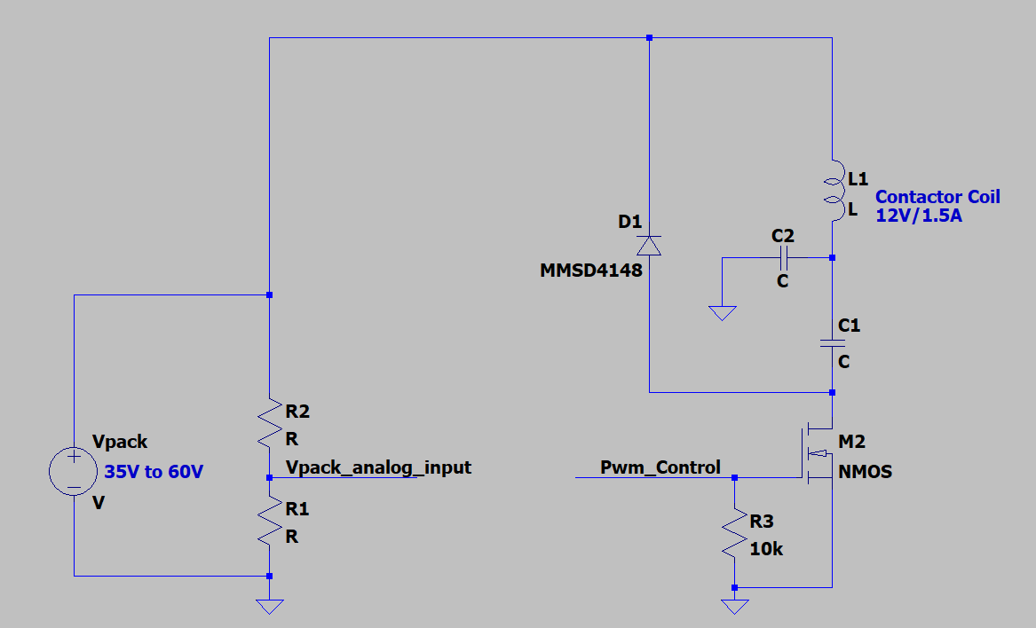
- Using the battery HV pack voltage(35-60V), I would like to control a 12V/1.5A coil of a contactor. The reason for that being the fact that the rest of the circuitry could be powered with a 5V/500mA buck converter and not having a 12V/2A supply only for the sake of contactor control would be nice.
- Would the following architecture for that purpose work in real life? Is there a better way of doing this?
- 
- -----
- Here is how the circuit should work. Vpack_analog_input is fed into the micro analog input. The circuit around L1, C1, and D1 serves as a flipped buck converter having an NMOS instead of a PMOS. C2 is providing a low impedance for the switching node because I fear the ringing would cause a significant amount of emissions on the input cable.
The idea is to sense the Vpack and initially allow M1 to be opened for no more than t=L1*Icoil/Vpack , and after that apply PWM to Pwm_Control and limit the duty cycle in order to never have more than a certain threshold of current flowing through L1(to be done through experimenting).
- I have a battery pack that consists of 18650 battery cells(14 cells in series max.). Hence, the voltage of the battery pack will be between 35V and 60V(to be on the safe side)
- I am designing a BMS in order to control it with cell monitoring, analog measurements, contactor control, etc. features built-in.
- Using the battery HV pack voltage(35-60V), I would like to control a 12V/1.5A coil of a contactor. The reason for that being the fact that the rest of the circuitry could be powered with a 5V/500mA buck converter and not having a 12V/2A supply only for the sake of contactor control would be nice.
- Would the following architecture for that purpose work in real life? Is there a better way of doing this?
- 
- -----
- Here is how the circuit should work. Vpack_analog_input is fed into the micro analog input. The circuit around L1, C1, and D1 serves as a flipped buck converter having an NMOS instead of a PMOS. C2 is providing a low impedance for the switching node because I fear the ringing would cause a significant amount of emissions on the input cable.
- The idea is to sense the Vpack and initially allow M2 to be opened for no more than t=L1*Icoil/Vpack , and after that apply PWM to Pwm_Control and limit the duty cycle in order to never have more than a certain threshold of current flowing through L1(to be done through experimenting).
#1: Initial revision
by
2kind
·
2021-06-09T21:10:11Z (almost 4 years ago)
Contactor control - Higher voltage PWM
I have a battery pack that consists of 18650 battery cells(14 cells in series max.). Hence, the voltage of the battery pack will be between 35V and 60V(to be on the safe side) I am designing a BMS in order to control it with cell monitoring, analog measurements, contactor control, etc. features built-in. Using the battery HV pack voltage(35-60V), I would like to control a 12V/1.5A coil of a contactor. The reason for that being the fact that the rest of the circuitry could be powered with a 5V/500mA buck converter and not having a 12V/2A supply only for the sake of contactor control would be nice. Would the following architecture for that purpose work in real life? Is there a better way of doing this?  ----- Here is how the circuit should work. Vpack_analog_input is fed into the micro analog input. The circuit around L1, C1, and D1 serves as a flipped buck converter having an NMOS instead of a PMOS. C2 is providing a low impedance for the switching node because I fear the ringing would cause a significant amount of emissions on the input cable. The idea is to sense the Vpack and initially allow M1 to be opened for no more than t=L1*Icoil/Vpack , and after that apply PWM to Pwm_Control and limit the duty cycle in order to never have more than a certain threshold of current flowing through L1(to be done through experimenting).