Post History
While your basic idea seems fine, I will not enter into this matter, especially after Olin has said he will. Instead, I will give some other ways to do that, that may be useful in other circumstan...
#5: Post edited
by
 coquelicot
·
2021-06-11T15:20:09Z (almost 4 years ago)
coquelicot
·
2021-06-11T15:20:09Z (almost 4 years ago)
If I understand right your question (please comment if that's not the case), you want to use the coil of the contactor as a part of a "tinkered" buck convertor, in order to abase the voltage of the battery pack that is way too large for powering this coil.While this idea seems licit, I will not enter into this matter, especially after Olin has said he will.The reason is that I think there are much better, or at least, much more practical and clean, ways to do that.First of all, you seem to believe that the only way to abase the voltage efficiently is to use inductor based buck convertor topologies; but there are inductorless convertors, working with capacitors, that are much cheaper and much less noisy.- This one for example, is one of the infinitely many convertors you can found on the market for very cheap.
- 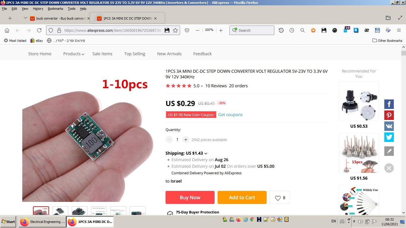
- And they are ready to use, no need to experiment, which can be a mess for a person not well used with convertors.
So, my first advice is:- _if you have no particular reason to build a buck convertor, buy one; after all, why doing by yourself what you can buy at low price._
And if you are not satisfied with bought convertors (e.g. if your supply voltage is too high), my second advice is:- _Take the schematic of a convertor another person has built and tested, and build exactly the same one, adapting if necessary few components._
- In fact, for very simple tasks **where the load is fixed** (as in your question), even a simple LM555 can do, a fact that seems not to be well known. Here is how (I assume you know how to mount 555 oscillators):
- * If the supply voltage is too high, power the 555 with a resistor + zener. The output should have a voltage of 10V (say) in order to switch a mosfet;
- * Mount the 555 as a square wave generator with variable duty cycle;
- * Then use the output of the 555 to switch a Mosfet feeding the load (the coil in your case) from the main supply;
- * add a capacitor in parallel to the load to smooth the voltage;
- * set the duty cycle of the 555 to obtain the desired voltage at the load.
- Please, note also the following: you say you have a battery pack where batteries are mounted in series, and it should provide a voltage between 35 and 60V.
- So, why not manage to introduce a terminal at half the battery chain, or even 1/3 of it? In this way, the voltage would be between 17V - 30V or 12V - 24V, which is easier to deal with.
After you have many ways to abase the voltage efficiently without having to design complicated things by yourselves, here is a power saver circuit I "invented" once and that worked well for me (in this schematic, I assume there is a 1$ small buck convertor with fixed 5V output, but any other solution mentioned above to obtain a fixed voltage will do):- 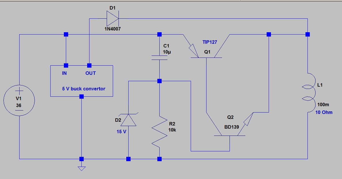
- The principle of operation is simple: at startup, the cap is not charged and the Sziklai pair Q1-Q2 conducts the current from the main supply, restricting it to somewhat below 15V because of the Zener D2.
- As cap C1 is charging, the voltage decreases, until it comes below 5V (and eventually stop conducting). At this point, diode D1 that was preventing the buck convertor to feed the load opens, and the buck convertor feeds the contactor coil at 5V, which is sufficient because of its hysteresis.
- Here is a simulation of the above circuit:
- 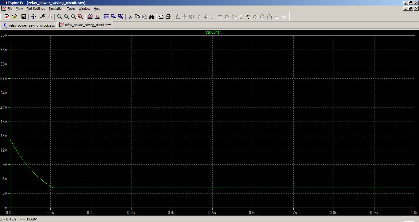
- An advantage of this power saver circuit is that you can control everything easily; in particular, by increasing the value of the cap, you can increase the switching delay time.
- While your basic idea seems fine, I will not enter into this matter, especially after Olin has said he will.
- Instead, I will give some other ways to do that, that may be useful in other circumstances.
- First of all, there are also inductorless convertors, working with capacitors, that are much cheaper and much less noisy.
- This one for example, is one of the infinitely many convertors you can found on the market for very cheap.
- 
- And they are ready to use, no need to experiment, which can be a mess for a person not well used with convertors.
- So, my first advice would be:
- _if you have no particular reason to build a buck convertor, buy one; after all, why doing by yourself what you can buy at low price._
- And if you are not satisfied with bought convertors (e.g. if your supply voltage is too high), my second advice would be:
- _Take the schematic of a convertor another person has built and tested, and build exactly the same one, adapting if necessary few components._
- In fact, for very simple tasks **where the load is fixed** (as in your question), even a simple LM555 can do, a fact that seems not to be well known. Here is how (I assume you know how to mount 555 oscillators):
- * If the supply voltage is too high, power the 555 with a resistor + zener. The output should have a voltage of 10V (say) in order to switch a mosfet;
- * Mount the 555 as a square wave generator with variable duty cycle;
- * Then use the output of the 555 to switch a Mosfet feeding the load (the coil in your case) from the main supply;
- * add a capacitor in parallel to the load to smooth the voltage;
- * set the duty cycle of the 555 to obtain the desired voltage at the load.
- Please, note also the following: you say you have a battery pack where batteries are mounted in series, and it should provide a voltage between 35 and 60V.
- So, why not manage to introduce a terminal at half the battery chain, or even 1/3 of it? In this way, the voltage would be between 17V - 30V or 12V - 24V, which is easier to deal with.
- After there are many ways to abase the voltage efficiently without having to design complicated things, here is a power saver circuit I "invented" once and that worked well for me (in this schematic, I assume there is a 1$ small buck convertor with fixed 5V output, but any other solution mentioned above to obtain a fixed voltage will do):
- 
- The principle of operation is simple: at startup, the cap is not charged and the Sziklai pair Q1-Q2 conducts the current from the main supply, restricting it to somewhat below 15V because of the Zener D2.
- As cap C1 is charging, the voltage decreases, until it comes below 5V (and eventually stop conducting). At this point, diode D1 that was preventing the buck convertor to feed the load opens, and the buck convertor feeds the contactor coil at 5V, which is sufficient because of its hysteresis.
- Here is a simulation of the above circuit:
- 
- An advantage of this power saver circuit is that you can control everything easily; in particular, by increasing the value of the cap, you can increase the switching delay time.
#4: Post edited
by
coquelicot
·
2021-06-11T06:45:04Z (almost 4 years ago)
- If I understand right your question (please comment if that's not the case), you want to use the coil of the contactor as a part of a "tinkered" buck convertor, in order to abase the voltage of the battery pack that is way too large for powering this coil.
- While this idea seems licit, I will not enter into this matter, especially after Olin has said he will.
- The reason is that I think there are much better, or at least, much more practical and clean, ways to do that.
- First of all, you seem to believe that the only way to abase the voltage efficiently is to use inductor based buck convertor topologies; but there are inductorless convertors, working with capacitors, that are much cheaper and much less noisy.
- This one for example, is one of the infinitely many convertors you can found on the market for very cheap.
- 
- And they are ready to use, no need to experiment, which can be a mess for a person not well used with convertors.
- So, my first advice is:
- _if you have no particular reason to build a buck convertor, buy one; after all, why doing by yourself what you can buy at low price._
- And if you are not satisfied with bought convertors (e.g. if your supply voltage is too high), my second advice is:
- _Take the schematic of a convertor another person has built and tested, and build exactly the same one, adapting if necessary few components._
- In fact, for very simple tasks **where the load is fixed** (as in your question), even a simple LM555 can do, a fact that seems not to be well known. Here is how (I assume you know how to mount 555 oscillators):
- * If the supply voltage is too high, power the 555 with a resistor + zener. The output should have a voltage of 10V (say) in order to switch a mosfet;
- * Mount the 555 as a square wave generator with variable duty cycle;
- * Then use the output of the 555 to switch a Mosfet feeding the load (the coil in your case) from the main supply;
- * add a capacitor in parallel to the load to smooth the voltage;
- * set the duty cycle of the 555 to obtain the desired voltage at the load.
- Please, note also the following: you say you have a battery pack where batteries are mounted in series, and it should provide a voltage between 35 and 60V.
- So, why not manage to introduce a terminal at half the battery chain, or even 1/3 of it? In this way, the voltage would be between 17V - 30V or 12V - 24V, which is easier to deal with.
- After you have many ways to abase the voltage efficiently without having to design complicated things by yourselves, here is a power saver circuit I "invented" once and that worked well for me (in this schematic, I assume there is a 1$ small buck convertor with fixed 5V output, but any other solution mentioned above to obtain a fixed voltage will do):
- 
- The principle of operation is simple: at startup, the cap is not charged and the Sziklai pair Q1-Q2 conducts the current from the main supply, restricting it to somewhat below 15V because of the Zener D2.
- As cap C1 is charging, the voltage decreases, until it comes below 5V (and eventually stop conducting). At this point, diode D1 that was preventing the buck convertor to feed the load opens, and the buck convertor feeds the contactor coil at 5V, which is sufficient because of its hysteresis.
- Here is a simulation of the above circuit:
- 
- An advantage of this power saver circuit is that you can control everything easily; in particular, by increasing the value of the cap, you can increase the switching delay time.
#3: Post edited
by
coquelicot
·
2021-06-11T06:37:32Z (almost 4 years ago)
- If I understand right your question (please comment if that's not the case), you want to use the coil of the contactor as a part of a "tinkered" buck convertor, in order to abase the voltage of the battery pack that is way too large for powering this coil.
- While this idea seems licit, I will not enter into this matter, especially after Olin has said he will.
- The reason is that I think there are much better, or at least, much more practical and clean, ways to do that.
- First of all, you seem to believe that the only way to abase the voltage efficiently is to use inductor based buck convertor topologies; but there are inductorless convertors, working with capacitors, that are much cheaper and much less noisy.
- This one for example, is one of the infinitely many convertors you can found on the market for very cheap.
- 
- And they are ready to use, no need to experiment, which can be a mess for a person not well used with convertors.
- So, my first advice is:
- _if you have no particular reason to build a buck convertor, buy one; after all, why doing by yourself what you can buy at low price._
- And if you are not satisfied with bought convertors (e.g. if your supply voltage is too high), my second advice is:
- _Take the schematic of a convertor another person has built and tested, and build exactly the same one, adapting if necessary few components._
- In fact, for very simple tasks **where the load is fixed** (as in your question), even a simple LM555 can do, a fact that seems not to be well known. Here is how (I assume you know how to mount 555 oscillators):
- * If the supply voltage is too high, power the 555 with a resistor + zener. The output should have a voltage of 10V (say) in order to switch a mosfet;
- * Mount the 555 as a square wave generator with variable duty cycle;
- * Then use the output of the 555 to switch a Mosfet feeding the load (the coil in your case) from the main supply;
- * add a capacitor in parallel to the load to smooth the voltage;
- * set the duty cycle of the 555 to obtain the desired voltage at the load.
Please, not also the following: you say you have a battery pack where batteries are mounted in series, and it should provide a voltage between 35 and 60V.- So, why not manage to introduce a terminal at half the battery chain, or even 1/3 of it? In this way, the voltage would be between 17V - 30V or 12V - 24V, which is easier to deal with.
- After you have many ways to abase the voltage efficiently without having to design complicated things by yourselves, here is a power saver circuit I "invented" once and that worked well for me (in this schematic, I assume there is a 1$ small buck convertor with fixed 5V output, but any other solution mentioned above to obtain a fixed voltage will do):
- 
- The principle of operation is simple: at startup, the cap is not charged and the Sziklai pair Q1-Q2 conducts the current from the main supply, restricting it to somewhat below 15V because of the Zener D2.
- As cap C1 is charging, the voltage decreases, until it comes below 5V (and eventually stop conducting). At this point, diode D1 that was preventing the buck convertor to feed the load opens, and the buck convertor feeds the contactor coil at 5V, which is sufficient because of its hysteresis.
- Here is a simulation of the above circuit:
- 
- If I understand right your question (please comment if that's not the case), you want to use the coil of the contactor as a part of a "tinkered" buck convertor, in order to abase the voltage of the battery pack that is way too large for powering this coil.
- While this idea seems licit, I will not enter into this matter, especially after Olin has said he will.
- The reason is that I think there are much better, or at least, much more practical and clean, ways to do that.
- First of all, you seem to believe that the only way to abase the voltage efficiently is to use inductor based buck convertor topologies; but there are inductorless convertors, working with capacitors, that are much cheaper and much less noisy.
- This one for example, is one of the infinitely many convertors you can found on the market for very cheap.
- 
- And they are ready to use, no need to experiment, which can be a mess for a person not well used with convertors.
- So, my first advice is:
- _if you have no particular reason to build a buck convertor, buy one; after all, why doing by yourself what you can buy at low price._
- And if you are not satisfied with bought convertors (e.g. if your supply voltage is too high), my second advice is:
- _Take the schematic of a convertor another person has built and tested, and build exactly the same one, adapting if necessary few components._
- In fact, for very simple tasks **where the load is fixed** (as in your question), even a simple LM555 can do, a fact that seems not to be well known. Here is how (I assume you know how to mount 555 oscillators):
- * If the supply voltage is too high, power the 555 with a resistor + zener. The output should have a voltage of 10V (say) in order to switch a mosfet;
- * Mount the 555 as a square wave generator with variable duty cycle;
- * Then use the output of the 555 to switch a Mosfet feeding the load (the coil in your case) from the main supply;
- * add a capacitor in parallel to the load to smooth the voltage;
- * set the duty cycle of the 555 to obtain the desired voltage at the load.
- Please, note also the following: you say you have a battery pack where batteries are mounted in series, and it should provide a voltage between 35 and 60V.
- So, why not manage to introduce a terminal at half the battery chain, or even 1/3 of it? In this way, the voltage would be between 17V - 30V or 12V - 24V, which is easier to deal with.
- After you have many ways to abase the voltage efficiently without having to design complicated things by yourselves, here is a power saver circuit I "invented" once and that worked well for me (in this schematic, I assume there is a 1$ small buck convertor with fixed 5V output, but any other solution mentioned above to obtain a fixed voltage will do):
- 
- The principle of operation is simple: at startup, the cap is not charged and the Sziklai pair Q1-Q2 conducts the current from the main supply, restricting it to somewhat below 15V because of the Zener D2.
- As cap C1 is charging, the voltage decreases, until it comes below 5V (and eventually stop conducting). At this point, diode D1 that was preventing the buck convertor to feed the load opens, and the buck convertor feeds the contactor coil at 5V, which is sufficient because of its hysteresis.
- Here is a simulation of the above circuit:
- 
#2: Post edited
by
coquelicot
·
2021-06-11T06:35:35Z (almost 4 years ago)
- If I understand right your question (please comment if that's not the case), you want to use the coil of the contactor as a part of a "tinkered" buck convertor, in order to abase the voltage of the battery pack that is way too large for powering this coil.
- While this idea seems licit, I will not enter into this matter, especially after Olin has said he will.
- The reason is that I think there are much better, or at least, much more practical and clean, ways to do that.
- First of all, you seem to believe that the only way to abase the voltage efficiently is to use inductor based buck convertor topologies; but there are inductorless convertors, working with capacitors, that are much cheaper and much less noisy.
This one for example, is one of the infinitely many convertor you can found on the market for very cheap.- 
- And they are ready to use, no need to experiment, which can be a mess for a person not well used with convertors.
- So, my first advice is:
- _if you have no particular reason to build a buck convertor, buy one; after all, why doing by yourself what you can buy at low price._
- And if you are not satisfied with bought convertors (e.g. if your supply voltage is too high), my second advice is:
- _Take the schematic of a convertor another person has built and tested, and build exactly the same one, adapting if necessary few components._
- In fact, for very simple tasks **where the load is fixed** (as in your question), even a simple LM555 can do, a fact that seems not to be well known. Here is how (I assume you know how to mount 555 oscillators):
- * If the supply voltage is too high, power the 555 with a resistor + zener. The output should have a voltage of 10V (say) in order to switch a mosfet;
- * Mount the 555 as a square wave generator with variable duty cycle;
- * Then use the output of the 555 to switch a Mosfet feeding the load (the coil in your case) from the main supply;
- * add a capacitor in parallel to the load to smooth the voltage;
- * set the duty cycle of the 555 to obtain the desired voltage at the load.
- Please, not also the following: you say you have a battery pack where batteries are mounted in series, and it should provide a voltage between 35 and 60V.
- So, why not manage to introduce a terminal at half the battery chain, or even 1/3 of it? In this way, the voltage would be between 17V - 30V or 12V - 24V, which is easier to deal with.
- After you have many ways to abase the voltage efficiently without having to design complicated things by yourselves, here is a power saver circuit I "invented" once and that worked well for me (in this schematic, I assume there is a 1$ small buck convertor with fixed 5V output, but any other solution mentioned above to obtain a fixed voltage will do):
- 
- The principle of operation is simple: at startup, the cap is not charged and the Sziklai pair Q1-Q2 conducts the current from the main supply, restricting it to somewhat below 15V because of the Zener D2.
- As cap C1 is charging, the voltage decreases, until it comes below 5V (and eventually stop conducting). At this point, diode D1 that was preventing the buck convertor to feed the load opens, and the buck convertor feeds the contactor coil at 5V, which is sufficient because of its hysteresis.
- Here is a simulation of the above circuit:
- 
- If I understand right your question (please comment if that's not the case), you want to use the coil of the contactor as a part of a "tinkered" buck convertor, in order to abase the voltage of the battery pack that is way too large for powering this coil.
- While this idea seems licit, I will not enter into this matter, especially after Olin has said he will.
- The reason is that I think there are much better, or at least, much more practical and clean, ways to do that.
- First of all, you seem to believe that the only way to abase the voltage efficiently is to use inductor based buck convertor topologies; but there are inductorless convertors, working with capacitors, that are much cheaper and much less noisy.
- This one for example, is one of the infinitely many convertors you can found on the market for very cheap.
- 
- And they are ready to use, no need to experiment, which can be a mess for a person not well used with convertors.
- So, my first advice is:
- _if you have no particular reason to build a buck convertor, buy one; after all, why doing by yourself what you can buy at low price._
- And if you are not satisfied with bought convertors (e.g. if your supply voltage is too high), my second advice is:
- _Take the schematic of a convertor another person has built and tested, and build exactly the same one, adapting if necessary few components._
- In fact, for very simple tasks **where the load is fixed** (as in your question), even a simple LM555 can do, a fact that seems not to be well known. Here is how (I assume you know how to mount 555 oscillators):
- * If the supply voltage is too high, power the 555 with a resistor + zener. The output should have a voltage of 10V (say) in order to switch a mosfet;
- * Mount the 555 as a square wave generator with variable duty cycle;
- * Then use the output of the 555 to switch a Mosfet feeding the load (the coil in your case) from the main supply;
- * add a capacitor in parallel to the load to smooth the voltage;
- * set the duty cycle of the 555 to obtain the desired voltage at the load.
- Please, not also the following: you say you have a battery pack where batteries are mounted in series, and it should provide a voltage between 35 and 60V.
- So, why not manage to introduce a terminal at half the battery chain, or even 1/3 of it? In this way, the voltage would be between 17V - 30V or 12V - 24V, which is easier to deal with.
- After you have many ways to abase the voltage efficiently without having to design complicated things by yourselves, here is a power saver circuit I "invented" once and that worked well for me (in this schematic, I assume there is a 1$ small buck convertor with fixed 5V output, but any other solution mentioned above to obtain a fixed voltage will do):
- 
- The principle of operation is simple: at startup, the cap is not charged and the Sziklai pair Q1-Q2 conducts the current from the main supply, restricting it to somewhat below 15V because of the Zener D2.
- As cap C1 is charging, the voltage decreases, until it comes below 5V (and eventually stop conducting). At this point, diode D1 that was preventing the buck convertor to feed the load opens, and the buck convertor feeds the contactor coil at 5V, which is sufficient because of its hysteresis.
- Here is a simulation of the above circuit:
- 
#1: Initial revision
by
coquelicot
·
2021-06-11T06:29:59Z (almost 4 years ago)
If I understand right your question (please comment if that's not the case), you want to use the coil of the contactor as a part of a "tinkered" buck convertor, in order to abase the voltage of the battery pack that is way too large for powering this coil. While this idea seems licit, I will not enter into this matter, especially after Olin has said he will. The reason is that I think there are much better, or at least, much more practical and clean, ways to do that. First of all, you seem to believe that the only way to abase the voltage efficiently is to use inductor based buck convertor topologies; but there are inductorless convertors, working with capacitors, that are much cheaper and much less noisy. This one for example, is one of the infinitely many convertor you can found on the market for very cheap.  And they are ready to use, no need to experiment, which can be a mess for a person not well used with convertors. So, my first advice is: _if you have no particular reason to build a buck convertor, buy one; after all, why doing by yourself what you can buy at low price._ And if you are not satisfied with bought convertors (e.g. if your supply voltage is too high), my second advice is: _Take the schematic of a convertor another person has built and tested, and build exactly the same one, adapting if necessary few components._ In fact, for very simple tasks **where the load is fixed** (as in your question), even a simple LM555 can do, a fact that seems not to be well known. Here is how (I assume you know how to mount 555 oscillators): * If the supply voltage is too high, power the 555 with a resistor + zener. The output should have a voltage of 10V (say) in order to switch a mosfet; * Mount the 555 as a square wave generator with variable duty cycle; * Then use the output of the 555 to switch a Mosfet feeding the load (the coil in your case) from the main supply; * add a capacitor in parallel to the load to smooth the voltage; * set the duty cycle of the 555 to obtain the desired voltage at the load. Please, not also the following: you say you have a battery pack where batteries are mounted in series, and it should provide a voltage between 35 and 60V. So, why not manage to introduce a terminal at half the battery chain, or even 1/3 of it? In this way, the voltage would be between 17V - 30V or 12V - 24V, which is easier to deal with. After you have many ways to abase the voltage efficiently without having to design complicated things by yourselves, here is a power saver circuit I "invented" once and that worked well for me (in this schematic, I assume there is a 1$ small buck convertor with fixed 5V output, but any other solution mentioned above to obtain a fixed voltage will do):  The principle of operation is simple: at startup, the cap is not charged and the Sziklai pair Q1-Q2 conducts the current from the main supply, restricting it to somewhat below 15V because of the Zener D2. As cap C1 is charging, the voltage decreases, until it comes below 5V (and eventually stop conducting). At this point, diode D1 that was preventing the buck convertor to feed the load opens, and the buck convertor feeds the contactor coil at 5V, which is sufficient because of its hysteresis. Here is a simulation of the above circuit: 