Post History
I don't know how to attach images to a comment thread, so I will just open up an answer for this. I redrew the schematic for you to reference. I think that symbol at the top of your drawing prob...
#2: Post edited
by
 cosined
·
2021-07-08T20:16:50Z (almost 4 years ago)
cosined
·
2021-07-08T20:16:50Z (almost 4 years ago)
- I don't know how to attach images to a comment thread, so I will just open up an answer for this. I redrew the schematic for you to reference.
- 
- I _think_ that symbol at the top of your drawing probably represents a switch. We are likely looking at damping when the switch closes. We want to see what happens when the capacitor has a 2V difference across it (fully charged), and then the switch suddenly opens.
- I myself am terrible at math and derivations, but I think I found the [goal formula](https://www.coilgun.info/theoryinductors/critical_damping.htm) for you to [aim for](http://www.nessengr.com/technical-data/series-rlc-circuit-equations/): the current
Someone who is actually good at math should be able to guide you to the derivation, but hoped this helped a little bit.
- I don't know how to attach images to a comment thread, so I will just open up an answer for this. I redrew the schematic for you to reference.
- 
- I _think_ that symbol at the top of your drawing probably represents a switch. We are likely looking at damping when the switch closes. We want to see what happens when the capacitor has a 2V difference across it (fully charged), and then the switch suddenly opens.
- I myself am terrible at math and derivations, but I think I found the [goal formula](https://www.coilgun.info/theoryinductors/critical_damping.htm) for you to [aim for](http://www.nessengr.com/technical-data/series-rlc-circuit-equations/): the current
- Someone who is actually good at math should be able to guide you to the derivation, but hoped this helped a little bit.
- -----
- **UPDATE**
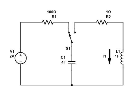
- Dave Tweed helpfully pointed out that my schematic above is probably wrong in terms of what the OP wanted. It _definitely_ is wrong with my own interpretation of what the OP wanted, though... Lol. Dave understands me better than I do.
- I fixed the circuit schematic below:
- 
#1: Initial revision
by
cosined
·
2021-07-08T06:59:59Z (almost 4 years ago)
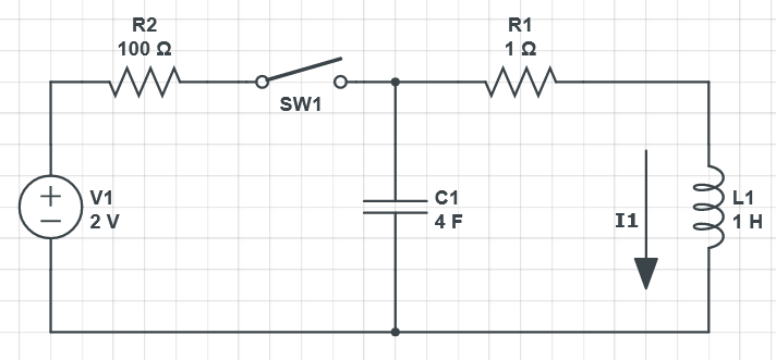
I don't know how to attach images to a comment thread, so I will just open up an answer for this. I redrew the schematic for you to reference.

I _think_ that symbol at the top of your drawing probably represents a switch. We are likely looking at damping when the switch closes. We want to see what happens when the capacitor has a 2V difference across it (fully charged), and then the switch suddenly opens.
I myself am terrible at math and derivations, but I think I found the [goal formula](https://www.coilgun.info/theoryinductors/critical_damping.htm) for you to [aim for](http://www.nessengr.com/technical-data/series-rlc-circuit-equations/): the current $I1$ in a critically-damped, series RLC circuit. I used MathJax as recommended by Olin.
$$I(t)=\frac{V_0}{L}te^\frac{-Rt}{2L}$$
$$\frac{R}{2L} = \alpha$$
$\alpha$ is the attenuation for this particular circuit configuration (series RLC).
Someone who is actually good at math should be able to guide you to the derivation, but hoped this helped a little bit.