Post History
You can use various methods for it, one way would be to simply use the ideal transfer function and make it in parallel with $R_o$: $$\begin{align} A(s)&=R_{th}+\dfrac{1}{sC_{th}} \tag{1} \\ ...
#1: Initial revision
by
 a concerned citizen
·
2021-08-21T17:10:30Z (almost 4 years ago)
a concerned citizen
·
2021-08-21T17:10:30Z (almost 4 years ago)
You can use various methods for it, one way would be to simply use the ideal transfer function and make it in parallel with \$R_o\$:
$$\begin{align}
A(s)&=R_{th}+\dfrac{1}{sC_{th}} \tag{1} \\\\
B(s)&=A(s)||C_{thp} \\\\
{}&=\dfrac{1}{\dfrac{1}{R_{th}+\dfrac{1}{sC_{th}}}+sC_{thp}} \\\\
{}&=\dfrac{1}{sC_{thp}}\dfrac{s+\dfrac{1}{R_{th}C_{th}}}{s+\dfrac{1}{R_{th}(C_{th}||C_{thp})}} \tag{2} \\\\
H(s)&=B(s)||R_o \\\\
{}&=\dfrac{1}{C_{thp}}\dfrac{s+\dfrac{1}{R_{th}C_{th}}}{s^2+\left[\dfrac{1}{R_oC_{thp}}+\dfrac{1}{R_{th}(C_{th}||C_{thp})}\right]s+\dfrac{1}{R_oR_{th}C_{th}C_{thp}}} \tag{3}
\end{align}$$
(2) would be the ideal transfer function, with the perfect zero at DC, while (3) is the final transfer function, as derived. Note that you are not using the correct poles/zeroes, and in their paper they are using \$\dfrac{1}{R_{th}C_{th}}\$ for \$s_{po}\$, but that's before adding the rest, so some modifications are needed. To test it, use your preferred SPICE, or whatever mathematical solver. I used the modified transfer function for the paper equivalent, while for the derived t.f. I used the more compact version (it's the same, you can verify it):
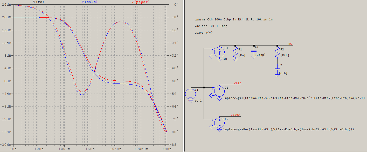
The values are bogus but the results are what matter: the traces are very close. They should be overlapping, I'll check it again later, but even if they don't, they come very close, particularly since what really matters is the phase.
As for calculating the output impedance, it depends on the values of the elements but, no, only \$C_{th}\$ is not enough. The most simple reason is that \$C_{th}\$ is used to calculate both a pole (\$C_{th}||C_{thp}\$) and a zero (and this disregarding the series \$R_{th}\$), therefore the whole response changes. So you have to consider the whole transfer function, but it should be (fairly) easier since it's a transconductance, therefore a function of current and voltage.