Post History
It all depends on the values of the components:If the system will very slowly decay until the energy of the system reaches 0. If the system undergoes something which will look like a part of...
#3: Post edited
by
 MissMulan
·
2021-09-08T16:07:51Z (over 3 years ago)
MissMulan
·
2021-09-08T16:07:51Z (over 3 years ago)
- It all depends on the values of the components:If
- 
- the system will very slowly decay until the energy of the system reaches 0.
- If
- 
- the system undergoes something which will look like a part of a oscillation and loses its energy very quickly
- If
- 
- it oscillates with decreasing amplitude until its energy reaches 0.
- In our case:
- 
- 
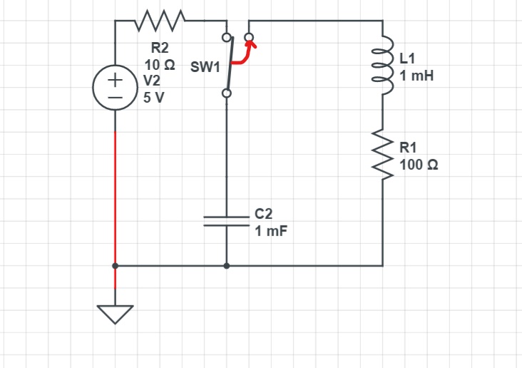
- it will very slowly decay without any oscillation.In order to find the equation of current of this RLC circuit we must be introduced to 2 things:
- Neper angular frequency -> a feature of damped systems
- In the case of the series RLC circuit it is:
- 
- The natural angular frequency -> the frequency response of the system under no damping
- In a RLC circuit it is equal to:
- 
- The equation of current of this overdamped system takes this form:
- 
- where :
- 
- (1)
- and:
- 
- Now lets go calculate s1 and s2:
- 
- After the switch is closed:
- 
- and due to L1:
- 
- so the voltage between L1 is:
- 
- By substituting the values of s1,s2 VL1(0+),L1 and IL1(0+) to (1) and solving the system we get:
- 
This is the equation of the current of the loop consisting of C1,L1,R2 after the switch is closed.
- It all depends on the values of the components:If
- 
- the system will very slowly decay until the energy of the system reaches 0.
- If
- 
- the system undergoes something which will look like a part of a oscillation and loses its energy very quickly
- If
- 
- it oscillates with decreasing amplitude until its energy reaches 0.
- In our case:
- 
- 
- it will very slowly decay without any oscillation.In order to find the equation of current of this RLC circuit we must be introduced to 2 things:
- Neper angular frequency -> a feature of damped systems
- In the case of the series RLC circuit it is:
- 
- The natural angular frequency -> the frequency response of the system under no damping
- In a RLC circuit it is equal to:
- 
- The equation of current of this overdamped system takes this form:
- 
- where :
- 
- (1)
- and:
- 
- Now lets go calculate s1 and s2:
- 
- After the switch is closed:
- 
- and due to L1:
- 
- so the voltage between L1 is:
- 
- By substituting the values of s1,s2 VL1(0+),L1 and IL1(0+) to (1) and solving the system we get:
- 
- This is the equation of the current of the loop consisting of C1,L1,R1 after the switch is closed.
#2: Post edited
by
MissMulan
·
2021-09-06T19:16:59Z (over 3 years ago)
- It all depends on the values of the components:If
- 
- the system will very slowly decay until the energy of the system reaches 0.
- If
- 
- the system undergoes something which will look like a part of a oscillation and loses its energy very quickly
- If
- 
- it oscillates with decreasing amplitude until its energy reaches 0.
- In our case:
since:- 
- it will very slowly decay without any oscillation.In order to find the equation of current of this RLC circuit we must be introduced to 2 things:
- Neper angular frequency -> a feature of damped systems
- In the case of the series RLC circuit it is:
- The natural angular frequency -> the frequency response of the system under no damping
- In a RLC circuit it is equal to:
- 
- The equation of current of this overdamped system takes this form:
- 
- where :
- 
- (1)
- and:
- 
- Now lets go calculate s1 and s2:
- 
- After the switch is closed:
- 
- and due to L1:
- 
- so the voltage between L1 is:
- 
By substituting the values of s1,s2 VL1(0+),L1 to (1) and solving the system we get:- 
- This is the equation of the current of the loop consisting of C1,L1,R2 after the switch is closed.
- It all depends on the values of the components:If
- 
- the system will very slowly decay until the energy of the system reaches 0.
- If
- 
- the system undergoes something which will look like a part of a oscillation and loses its energy very quickly
- If
- 
- it oscillates with decreasing amplitude until its energy reaches 0.
- In our case:
- 
- 
- it will very slowly decay without any oscillation.In order to find the equation of current of this RLC circuit we must be introduced to 2 things:
- Neper angular frequency -> a feature of damped systems
- In the case of the series RLC circuit it is:
- 
- The natural angular frequency -> the frequency response of the system under no damping
- In a RLC circuit it is equal to:
- 
- The equation of current of this overdamped system takes this form:
- 
- where :
- 
- (1)
- and:
- 
- Now lets go calculate s1 and s2:
- 
- After the switch is closed:
- 
- and due to L1:
- 
- so the voltage between L1 is:
- 
- By substituting the values of s1,s2 VL1(0+),L1 and IL1(0+) to (1) and solving the system we get:
- 
- This is the equation of the current of the loop consisting of C1,L1,R2 after the switch is closed.
#1: Initial revision
by
MissMulan
·
2021-09-06T17:03:40Z (over 3 years ago)
It all depends on the values of the components:If  the system will very slowly decay until the energy of the system reaches 0. If  the system undergoes something which will look like a part of a oscillation and loses its energy very quickly If  it oscillates with decreasing amplitude until its energy reaches 0. In our case:  since:  it will very slowly decay without any oscillation.In order to find the equation of current of this RLC circuit we must be introduced to 2 things: Neper angular frequency -> a feature of damped systems In the case of the series RLC circuit it is:  The natural angular frequency -> the frequency response of the system under no damping In a RLC circuit it is equal to:  The equation of current of this overdamped system takes this form:  where :  (1) and:  Now lets go calculate s1 and s2:  After the switch is closed:  and due to L1:  so the voltage between L1 is:  By substituting the values of s1,s2 VL1(0+),L1 to (1) and solving the system we get:  This is the equation of the current of the loop consisting of C1,L1,R2 after the switch is closed.