Post History
Modern CAN transceivers like MCP2561FD that support CAN FD with high baudrates come with an optional feature called SPLIT, which is to my understanding a reference voltage output pin used to give a...
#1: Initial revision
by
 Lundin
·
2021-09-24T09:21:28Z (over 3 years ago)
Lundin
·
2021-09-24T09:21:28Z (over 3 years ago)
CAN "split" pin, bus termination and common mode stabilization
Modern CAN transceivers like [MCP2561FD](https://www.microchip.com/en-us/product/MCP2561FD) that support CAN FD with high baudrates come with an optional feature called SPLIT, which is to my understanding a reference voltage output pin used to give a common mode stabilization and thereby reduce radiated emissions. It gives out 0.5V<sub>dd</sub> so that would be the 2.5V idle voltage of CAN. Example application from the above linked datasheet: 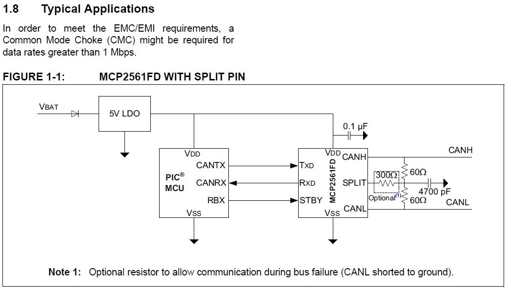 They don't show where the mentioned common mode choke should be placed. I've always used one and usually place it between the transceiver and the 120R terminating resistor. But it would seem that they've placed the SPLIT pin at the centre of the terminating resistors? Can anyone explain the theory behind this pin and at what speeds it might become useful? Am I correct in assuming the 60R + 60R are the terminating resistors? If so, what if the node is not the last one on the bus? How to connect this pin then? And where to place the common mode choke?