Post History
This answer is regarding the resonance issue that C2 is fixing, and how it could be done with a smaller cap. There are two aspects of it. To start, consider the 5.6uH vs the 10uF capacitors. It ca...
#12: Post edited
by
 Pete W
·
2021-10-29T02:07:23Z (over 3 years ago)
Pete W
·
2021-10-29T02:07:23Z (over 3 years ago)
- This answer is regarding the resonance issue that C2 is fixing, and how it could be done with a smaller cap.
- There are two aspects of it. To start, consider the 5.6uH vs the 10uF capacitors. It can be stopped from resonating with the addition of a series resistor. With the modest DC current (powering only the micro) and plenty of voltage to spare, it shouldn't cause trouble.
- Once the resonance from the 5.6uH is out of the picture, it becomes easier to examine the 24V node. This node vs the inductance of the incoming +24V supply (and return) wires will also be very underdamped. Even if the resonance is not excited by the circuit's operation, it will still produce an overshoot upon turn-on. It can be damped with a parallel (R+C) shunting the low-ESR capacitance on the +24V. This is what the 2200uF cap with its larger ESR is doing, but we can get the same damping with less capacitance. It is the R in the parallel damping network that really matters, the C in the parallel damping network only has to be big enough so that the parallel (R+C) has significantly lower impedance (at the resonant frequency) compared to the low-ESR C we are "fixing". I found that 5x the low-ESR C seems to work well.
- ----
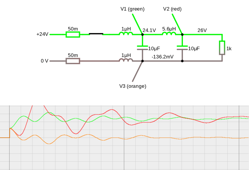
- Here is a crude (qualitative purposes) simulation without the damping. V1 is the 24V node. I assumed the minimal 10uF capacitance on the 24V node. 1uH "wire inductance" arbitrarily chosen to illustrate the concept as I think is relevant here, not really a properly modeled wire.
- (graphs: 10V/div and 10us/div, click for link)
- [](https://www.falstad.com/circuit/circuitjs.html?ctz=CQAgjOCmC0CcIGYAcA6AbLNAWbBWLYATFrGGFiIQiLiFtbjGQFADOI0Ch4WFXPFAAwhhAMwCGAG1aRmAJQ5Jh5CtCJIBIrVmHEtwwSlzNJibivBFNBlILt2IB5gGNL53m8qCNN+3dgBgUHB8IZ+go62fmDMAO5mXhqc3ITeIvKKumlqhBqpPtoG+iJGJpoW+dYl4bho+nGeFk0ehC6JmpWVvn4hvYHV0QP2MfGdaWQpaa2j4x4IghQVDfMUY3lpgswATogLmivtyvbbmZrJVWHGO+eV0EqH1cam-JUTD2GDTqkA7I0e9-cKAA1MAAHVYAAoAOZbSCQAB2AEpmD92k1vnVASAgYRwRDYQATZGot6Ve6Eb7cYEIPEAey24nhUMgyNpIF+hFqWgAHkgwBFuPcPoJvnzOVpqPytFKjlpQuAnEA)
- And next, here is with some damping (again 10V/div, 10us/div, clickable). Note the series damping added to the 5.6uH and parallel damping (R+C) added to the 10uF on the "V1" (+24V node).
- [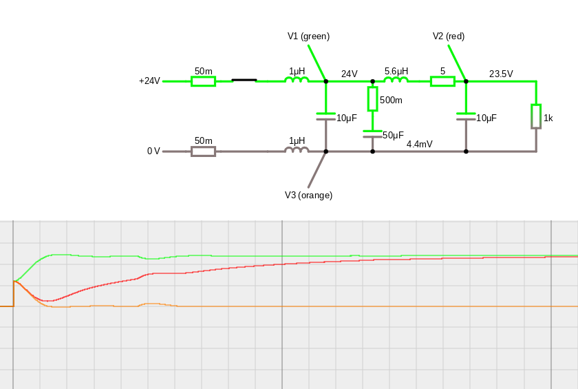
- ](https://www.falstad.com/circuit/circuitjs.html?ctz=CQAgjOCmC0CcIGYAcA6AbLNAWbBWLYATFrGGFiIQiLiFtbjGQFADOI0Ch4WFXPFAAwhhAMwCGAG1aRmAJQ5Jh5CtCJIBIrVmHEtwwSlzNJibivBFNBlILt2IB5gGNL53m8o79t+4NgBgUHB8IZ+go6+9mDMAO5mXsKc3MROCtBKiRzqWQZ0eQVGJuAA7GiaqdYiUXa45U7xZO4UYGUVLoiCLR4IXbnV4SFDgQN+keEx8b0Ula3llYRxnd0UOsoei-FrWdO5zABO+eurdv1g9geKxxz8FjaCxofJWRm63vfGpvyzVpX3Y-pmIRBCVPBZMpkKAA1MAAHVYAAoAOb7SCQAB2AEogSDlhUStxISAoYR4QjUQATbHA0FNLKZXbQhBkgD2+3E6KRkGxh12FlmHmExkabR+KXeHTmWSlYFg3H+dhIwxC9V84wilxlctK5Tu1WMLJAoMIdS0AA8kOcrJkwnYSpaTVpqOctC7lHlQuAnEA
- )
- ----
Since we shouldn't rely on a particular +24V/return wire being connected, it's not possible to pick the ideal parallel damping R. So I think a suppression diode (not shown) is really a good idea, to limit any overvoltages that remain. An avalanche diode with Vrwm=28V (Vbr=32V) should be about right. Another note is that the caps may be derated significantly at the +24V operating voltage, depending on the exact type.- Finally, to be clear, all the values (apart from suppression diode) above are illustrative, and don't take into account the needs of the "business end" of the circuit, although the resistive heater should be relatively benign.
- This answer is regarding the resonance issue that C2 is fixing, and how it could be done with a smaller cap.
- There are two aspects of it. To start, consider the 5.6uH vs the 10uF capacitors. It can be stopped from resonating with the addition of a series resistor. With the modest DC current (powering only the micro) and plenty of voltage to spare, it shouldn't cause trouble.
- Once the resonance from the 5.6uH is out of the picture, it becomes easier to examine the 24V node. This node vs the inductance of the incoming +24V supply (and return) wires will also be very underdamped. Even if the resonance is not excited by the circuit's operation, it will still produce an overshoot upon turn-on. It can be damped with a parallel (R+C) shunting the low-ESR capacitance on the +24V. This is what the 2200uF cap with its larger ESR is doing, but we can get the same damping with less capacitance. It is the R in the parallel damping network that really matters, the C in the parallel damping network only has to be big enough so that the parallel (R+C) has significantly lower impedance (at the resonant frequency) compared to the low-ESR C we are "fixing". I found that 5x the low-ESR C seems to work well.
- ----
- Here is a crude (qualitative purposes) simulation without the damping. V1 is the 24V node. I assumed the minimal 10uF capacitance on the 24V node. 1uH "wire inductance" arbitrarily chosen to illustrate the concept as I think is relevant here, not really a properly modeled wire.
- (graphs: 10V/div and 10us/div, click for link)
- [](https://www.falstad.com/circuit/circuitjs.html?ctz=CQAgjOCmC0CcIGYAcA6AbLNAWbBWLYATFrGGFiIQiLiFtbjGQFADOI0Ch4WFXPFAAwhhAMwCGAG1aRmAJQ5Jh5CtCJIBIrVmHEtwwSlzNJibivBFNBlILt2IB5gGNL53m8qCNN+3dgBgUHB8IZ+go62fmDMAO5mXhqc3ITeIvKKumlqhBqpPtoG+iJGJpoW+dYl4bho+nGeFk0ehC6JmpWVvn4hvYHV0QP2MfGdaWQpaa2j4x4IghQVDfMUY3lpgswATogLmivtyvbbmZrJVWHGO+eV0EqH1cam-JUTD2GDTqkA7I0e9-cKAA1MAAHVYAAoAOZbSCQAB2AEpmD92k1vnVASAgYRwRDYQATZGot6Ve6Eb7cYEIPEAey24nhUMgyNpIF+hFqWgAHkgwBFuPcPoJvnzOVpqPytFKjlpQuAnEA)
- And next, here is with some damping (again 10V/div, 10us/div, clickable). Note the series damping added to the 5.6uH and parallel damping (R+C) added to the 10uF on the "V1" (+24V node).
- [
- ](https://www.falstad.com/circuit/circuitjs.html?ctz=CQAgjOCmC0CcIGYAcA6AbLNAWbBWLYATFrGGFiIQiLiFtbjGQFADOI0Ch4WFXPFAAwhhAMwCGAG1aRmAJQ5Jh5CtCJIBIrVmHEtwwSlzNJibivBFNBlILt2IB5gGNL53m8o79t+4NgBgUHB8IZ+go6+9mDMAO5mXsKc3MROCtBKiRzqWQZ0eQVGJuAA7GiaqdYiUXa45U7xZO4UYGUVLoiCLR4IXbnV4SFDgQN+keEx8b0Ula3llYRxnd0UOsoei-FrWdO5zABO+eurdv1g9geKxxz8FjaCxofJWRm63vfGpvyzVpX3Y-pmIRBCVPBZMpkKAA1MAAHVYAAoAOb7SCQAB2AEogSDlhUStxISAoYR4QjUQATbHA0FNLKZXbQhBkgD2+3E6KRkGxh12FlmHmExkabR+KXeHTmWSlYFg3H+dhIwxC9V84wilxlctK5Tu1WMLJAoMIdS0AA8kOcrJkwnYSpaTVpqOctC7lHlQuAnEA
- )
- ----
- Since we shouldn't rely on a particular +24V/return wire being connected, it's not possible to pick the ideal parallel damping R. So I think a suppression diode (not shown) is really a good idea, to limit any overvoltages that remain. An avalanche diode with Vrwm=28V (Vbr=32V typ) should be about right. Another note is that the caps may be derated significantly at the +24V operating voltage, depending on the exact type.
- Finally, to be clear, all the values (apart from suppression diode) above are illustrative, and don't take into account the needs of the "business end" of the circuit, although the resistive heater should be relatively benign.
#11: Post edited
by
Pete W
·
2021-10-29T02:06:49Z (over 3 years ago)
- This answer is regarding the resonance issue that C2 is fixing, and how it could be done with a smaller cap.
- There are two aspects of it. To start, consider the 5.6uH vs the 10uF capacitors. It can be stopped from resonating with the addition of a series resistor. With the modest DC current (powering only the micro) and plenty of voltage to spare, it shouldn't cause trouble.
- Once the resonance from the 5.6uH is out of the picture, it becomes easier to examine the 24V node. This node vs the inductance of the incoming +24V supply (and return) wires will also be very underdamped. Even if the resonance is not excited by the circuit's operation, it will still produce an overshoot upon turn-on. It can be damped with a parallel (R+C) shunting the low-ESR capacitance on the +24V. This is what the 2200uF cap with its larger ESR is doing, but we can get the same damping with less capacitance. It is the R in the parallel damping network that really matters, the C in the parallel damping network only has to be big enough so that the parallel (R+C) has significantly lower impedance (at the resonant frequency) compared to the low-ESR C we are "fixing". I found that 5x the low-ESR C seems to work well.
- ----
- Here is a crude (qualitative purposes) simulation without the damping. V1 is the 24V node. I assumed the minimal 10uF capacitance on the 24V node. 1uH "wire inductance" arbitrarily chosen to illustrate the concept as I think is relevant here, not really a properly modeled wire.
- (graphs: 10V/div and 10us/div, click for link)
- [](https://www.falstad.com/circuit/circuitjs.html?ctz=CQAgjOCmC0CcIGYAcA6AbLNAWbBWLYATFrGGFiIQiLiFtbjGQFADOI0Ch4WFXPFAAwhhAMwCGAG1aRmAJQ5Jh5CtCJIBIrVmHEtwwSlzNJibivBFNBlILt2IB5gGNL53m8qCNN+3dgBgUHB8IZ+go62fmDMAO5mXhqc3ITeIvKKumlqhBqpPtoG+iJGJpoW+dYl4bho+nGeFk0ehC6JmpWVvn4hvYHV0QP2MfGdaWQpaa2j4x4IghQVDfMUY3lpgswATogLmivtyvbbmZrJVWHGO+eV0EqH1cam-JUTD2GDTqkA7I0e9-cKAA1MAAHVYAAoAOZbSCQAB2AEpmD92k1vnVASAgYRwRDYQATZGot6Ve6Eb7cYEIPEAey24nhUMgyNpIF+hFqWgAHkgwBFuPcPoJvnzOVpqPytFKjlpQuAnEA)
- And next, here is with some damping (again 10V/div, 10us/div, clickable). Note the series damping added to the 5.6uH and parallel damping (R+C) added to the 10uF on the "V1" (+24V node).
- [
- ](https://www.falstad.com/circuit/circuitjs.html?ctz=CQAgjOCmC0CcIGYAcA6AbLNAWbBWLYATFrGGFiIQiLiFtbjGQFADOI0Ch4WFXPFAAwhhAMwCGAG1aRmAJQ5Jh5CtCJIBIrVmHEtwwSlzNJibivBFNBlILt2IB5gGNL53m8o79t+4NgBgUHB8IZ+go6+9mDMAO5mXsKc3MROCtBKiRzqWQZ0eQVGJuAA7GiaqdYiUXa45U7xZO4UYGUVLoiCLR4IXbnV4SFDgQN+keEx8b0Ula3llYRxnd0UOsoei-FrWdO5zABO+eurdv1g9geKxxz8FjaCxofJWRm63vfGpvyzVpX3Y-pmIRBCVPBZMpkKAA1MAAHVYAAoAOb7SCQAB2AEogSDlhUStxISAoYR4QjUQATbHA0FNLKZXbQhBkgD2+3E6KRkGxh12FlmHmExkabR+KXeHTmWSlYFg3H+dhIwxC9V84wilxlctK5Tu1WMLJAoMIdS0AA8kOcrJkwnYSpaTVpqOctC7lHlQuAnEA
- )
- ----
- Since we shouldn't rely on a particular +24V/return wire being connected, it's not possible to pick the ideal parallel damping R. So I think a suppression diode (not shown) is really a good idea, to limit any overvoltages that remain. An avalanche diode with Vrwm=28V (Vbr=32V) should be about right. Another note is that the caps may be derated significantly at the +24V operating voltage, depending on the exact type.
Finally, to be clear, all the values above are illustrative, and don't take into account the needs of the "business end" of the circuit, although the resistive heater should be relatively benign.
- This answer is regarding the resonance issue that C2 is fixing, and how it could be done with a smaller cap.
- There are two aspects of it. To start, consider the 5.6uH vs the 10uF capacitors. It can be stopped from resonating with the addition of a series resistor. With the modest DC current (powering only the micro) and plenty of voltage to spare, it shouldn't cause trouble.
- Once the resonance from the 5.6uH is out of the picture, it becomes easier to examine the 24V node. This node vs the inductance of the incoming +24V supply (and return) wires will also be very underdamped. Even if the resonance is not excited by the circuit's operation, it will still produce an overshoot upon turn-on. It can be damped with a parallel (R+C) shunting the low-ESR capacitance on the +24V. This is what the 2200uF cap with its larger ESR is doing, but we can get the same damping with less capacitance. It is the R in the parallel damping network that really matters, the C in the parallel damping network only has to be big enough so that the parallel (R+C) has significantly lower impedance (at the resonant frequency) compared to the low-ESR C we are "fixing". I found that 5x the low-ESR C seems to work well.
- ----
- Here is a crude (qualitative purposes) simulation without the damping. V1 is the 24V node. I assumed the minimal 10uF capacitance on the 24V node. 1uH "wire inductance" arbitrarily chosen to illustrate the concept as I think is relevant here, not really a properly modeled wire.
- (graphs: 10V/div and 10us/div, click for link)
- [](https://www.falstad.com/circuit/circuitjs.html?ctz=CQAgjOCmC0CcIGYAcA6AbLNAWbBWLYATFrGGFiIQiLiFtbjGQFADOI0Ch4WFXPFAAwhhAMwCGAG1aRmAJQ5Jh5CtCJIBIrVmHEtwwSlzNJibivBFNBlILt2IB5gGNL53m8qCNN+3dgBgUHB8IZ+go62fmDMAO5mXhqc3ITeIvKKumlqhBqpPtoG+iJGJpoW+dYl4bho+nGeFk0ehC6JmpWVvn4hvYHV0QP2MfGdaWQpaa2j4x4IghQVDfMUY3lpgswATogLmivtyvbbmZrJVWHGO+eV0EqH1cam-JUTD2GDTqkA7I0e9-cKAA1MAAHVYAAoAOZbSCQAB2AEpmD92k1vnVASAgYRwRDYQATZGot6Ve6Eb7cYEIPEAey24nhUMgyNpIF+hFqWgAHkgwBFuPcPoJvnzOVpqPytFKjlpQuAnEA)
- And next, here is with some damping (again 10V/div, 10us/div, clickable). Note the series damping added to the 5.6uH and parallel damping (R+C) added to the 10uF on the "V1" (+24V node).
- [
- ](https://www.falstad.com/circuit/circuitjs.html?ctz=CQAgjOCmC0CcIGYAcA6AbLNAWbBWLYATFrGGFiIQiLiFtbjGQFADOI0Ch4WFXPFAAwhhAMwCGAG1aRmAJQ5Jh5CtCJIBIrVmHEtwwSlzNJibivBFNBlILt2IB5gGNL53m8o79t+4NgBgUHB8IZ+go6+9mDMAO5mXsKc3MROCtBKiRzqWQZ0eQVGJuAA7GiaqdYiUXa45U7xZO4UYGUVLoiCLR4IXbnV4SFDgQN+keEx8b0Ula3llYRxnd0UOsoei-FrWdO5zABO+eurdv1g9geKxxz8FjaCxofJWRm63vfGpvyzVpX3Y-pmIRBCVPBZMpkKAA1MAAHVYAAoAOb7SCQAB2AEogSDlhUStxISAoYR4QjUQATbHA0FNLKZXbQhBkgD2+3E6KRkGxh12FlmHmExkabR+KXeHTmWSlYFg3H+dhIwxC9V84wilxlctK5Tu1WMLJAoMIdS0AA8kOcrJkwnYSpaTVpqOctC7lHlQuAnEA
- )
- ----
- Since we shouldn't rely on a particular +24V/return wire being connected, it's not possible to pick the ideal parallel damping R. So I think a suppression diode (not shown) is really a good idea, to limit any overvoltages that remain. An avalanche diode with Vrwm=28V (Vbr=32V) should be about right. Another note is that the caps may be derated significantly at the +24V operating voltage, depending on the exact type.
- Finally, to be clear, all the values (apart from suppression diode) above are illustrative, and don't take into account the needs of the "business end" of the circuit, although the resistive heater should be relatively benign.
#10: Post edited
by
Pete W
·
2021-10-29T02:06:16Z (over 3 years ago)
- This answer is regarding the resonance issue that C2 is fixing, and how it could be done with a smaller cap.
- There are two aspects of it. To start, consider the 5.6uH vs the 10uF capacitors. It can be stopped from resonating with the addition of a series resistor. With the modest DC current (powering only the micro) and plenty of voltage to spare, it shouldn't cause trouble.
- Once the resonance from the 5.6uH is out of the picture, it becomes easier to examine the 24V node. This node vs the inductance of the incoming +24V supply (and return) wires will also be very underdamped. Even if the resonance is not excited by the circuit's operation, it will still produce an overshoot upon turn-on. It can be damped with a parallel (R+C) shunting the low-ESR capacitance on the +24V. This is what the 2200uF cap with its larger ESR is doing, but we can get the same damping with less capacitance. It is the R in the parallel damping network that really matters, the C in the parallel damping network only has to be big enough so that the parallel (R+C) has significantly lower impedance (at the resonant frequency) compared to the low-ESR C we are "fixing". I found that 5x the low-ESR C seems to work well.
- ----
- Here is a crude (qualitative purposes) simulation without the damping. V1 is the 24V node. I assumed the minimal 10uF capacitance on the 24V node. 1uH "wire inductance" arbitrarily chosen to illustrate the concept as I think is relevant here, not really a properly modeled wire.
- (graphs: 10V/div and 10us/div, click for link)
- [](https://www.falstad.com/circuit/circuitjs.html?ctz=CQAgjOCmC0CcIGYAcA6AbLNAWbBWLYATFrGGFiIQiLiFtbjGQFADOI0Ch4WFXPFAAwhhAMwCGAG1aRmAJQ5Jh5CtCJIBIrVmHEtwwSlzNJibivBFNBlILt2IB5gGNL53m8qCNN+3dgBgUHB8IZ+go62fmDMAO5mXhqc3ITeIvKKumlqhBqpPtoG+iJGJpoW+dYl4bho+nGeFk0ehC6JmpWVvn4hvYHV0QP2MfGdaWQpaa2j4x4IghQVDfMUY3lpgswATogLmivtyvbbmZrJVWHGO+eV0EqH1cam-JUTD2GDTqkA7I0e9-cKAA1MAAHVYAAoAOZbSCQAB2AEpmD92k1vnVASAgYRwRDYQATZGot6Ve6Eb7cYEIPEAey24nhUMgyNpIF+hFqWgAHkgwBFuPcPoJvnzOVpqPytFKjlpQuAnEA)
- And next, here is with some damping (again 10V/div, 10us/div, clickable). Note the series damping added to the 5.6uH and parallel damping (R+C) added to the 10uF on the "V1" (+24V node).
- [
- ](https://www.falstad.com/circuit/circuitjs.html?ctz=CQAgjOCmC0CcIGYAcA6AbLNAWbBWLYATFrGGFiIQiLiFtbjGQFADOI0Ch4WFXPFAAwhhAMwCGAG1aRmAJQ5Jh5CtCJIBIrVmHEtwwSlzNJibivBFNBlILt2IB5gGNL53m8o79t+4NgBgUHB8IZ+go6+9mDMAO5mXsKc3MROCtBKiRzqWQZ0eQVGJuAA7GiaqdYiUXa45U7xZO4UYGUVLoiCLR4IXbnV4SFDgQN+keEx8b0Ula3llYRxnd0UOsoei-FrWdO5zABO+eurdv1g9geKxxz8FjaCxofJWRm63vfGpvyzVpX3Y-pmIRBCVPBZMpkKAA1MAAHVYAAoAOb7SCQAB2AEogSDlhUStxISAoYR4QjUQATbHA0FNLKZXbQhBkgD2+3E6KRkGxh12FlmHmExkabR+KXeHTmWSlYFg3H+dhIwxC9V84wilxlctK5Tu1WMLJAoMIdS0AA8kOcrJkwnYSpaTVpqOctC7lHlQuAnEA
- )
- ----
Since we shouldn't rely on a particular +24V/return wire being connected, it's not possible to pick the ideal parallel damping R. So I think a suppression diode (not shown) is really a good idea, to limit any overvoltages that remain. An avalanche diode with Vrwm=28V (Vbr=32V) should be about right. Another note is that the caps may be derated significantly at the +24V operating voltage, depending on the exact type.
- This answer is regarding the resonance issue that C2 is fixing, and how it could be done with a smaller cap.
- There are two aspects of it. To start, consider the 5.6uH vs the 10uF capacitors. It can be stopped from resonating with the addition of a series resistor. With the modest DC current (powering only the micro) and plenty of voltage to spare, it shouldn't cause trouble.
- Once the resonance from the 5.6uH is out of the picture, it becomes easier to examine the 24V node. This node vs the inductance of the incoming +24V supply (and return) wires will also be very underdamped. Even if the resonance is not excited by the circuit's operation, it will still produce an overshoot upon turn-on. It can be damped with a parallel (R+C) shunting the low-ESR capacitance on the +24V. This is what the 2200uF cap with its larger ESR is doing, but we can get the same damping with less capacitance. It is the R in the parallel damping network that really matters, the C in the parallel damping network only has to be big enough so that the parallel (R+C) has significantly lower impedance (at the resonant frequency) compared to the low-ESR C we are "fixing". I found that 5x the low-ESR C seems to work well.
- ----
- Here is a crude (qualitative purposes) simulation without the damping. V1 is the 24V node. I assumed the minimal 10uF capacitance on the 24V node. 1uH "wire inductance" arbitrarily chosen to illustrate the concept as I think is relevant here, not really a properly modeled wire.
- (graphs: 10V/div and 10us/div, click for link)
- [](https://www.falstad.com/circuit/circuitjs.html?ctz=CQAgjOCmC0CcIGYAcA6AbLNAWbBWLYATFrGGFiIQiLiFtbjGQFADOI0Ch4WFXPFAAwhhAMwCGAG1aRmAJQ5Jh5CtCJIBIrVmHEtwwSlzNJibivBFNBlILt2IB5gGNL53m8qCNN+3dgBgUHB8IZ+go62fmDMAO5mXhqc3ITeIvKKumlqhBqpPtoG+iJGJpoW+dYl4bho+nGeFk0ehC6JmpWVvn4hvYHV0QP2MfGdaWQpaa2j4x4IghQVDfMUY3lpgswATogLmivtyvbbmZrJVWHGO+eV0EqH1cam-JUTD2GDTqkA7I0e9-cKAA1MAAHVYAAoAOZbSCQAB2AEpmD92k1vnVASAgYRwRDYQATZGot6Ve6Eb7cYEIPEAey24nhUMgyNpIF+hFqWgAHkgwBFuPcPoJvnzOVpqPytFKjlpQuAnEA)
- And next, here is with some damping (again 10V/div, 10us/div, clickable). Note the series damping added to the 5.6uH and parallel damping (R+C) added to the 10uF on the "V1" (+24V node).
- [
- ](https://www.falstad.com/circuit/circuitjs.html?ctz=CQAgjOCmC0CcIGYAcA6AbLNAWbBWLYATFrGGFiIQiLiFtbjGQFADOI0Ch4WFXPFAAwhhAMwCGAG1aRmAJQ5Jh5CtCJIBIrVmHEtwwSlzNJibivBFNBlILt2IB5gGNL53m8o79t+4NgBgUHB8IZ+go6+9mDMAO5mXsKc3MROCtBKiRzqWQZ0eQVGJuAA7GiaqdYiUXa45U7xZO4UYGUVLoiCLR4IXbnV4SFDgQN+keEx8b0Ula3llYRxnd0UOsoei-FrWdO5zABO+eurdv1g9geKxxz8FjaCxofJWRm63vfGpvyzVpX3Y-pmIRBCVPBZMpkKAA1MAAHVYAAoAOb7SCQAB2AEogSDlhUStxISAoYR4QjUQATbHA0FNLKZXbQhBkgD2+3E6KRkGxh12FlmHmExkabR+KXeHTmWSlYFg3H+dhIwxC9V84wilxlctK5Tu1WMLJAoMIdS0AA8kOcrJkwnYSpaTVpqOctC7lHlQuAnEA
- )
- ----
- Since we shouldn't rely on a particular +24V/return wire being connected, it's not possible to pick the ideal parallel damping R. So I think a suppression diode (not shown) is really a good idea, to limit any overvoltages that remain. An avalanche diode with Vrwm=28V (Vbr=32V) should be about right. Another note is that the caps may be derated significantly at the +24V operating voltage, depending on the exact type.
- Finally, to be clear, all the values above are illustrative, and don't take into account the needs of the "business end" of the circuit, although the resistive heater should be relatively benign.
#9: Post edited
by
Pete W
·
2021-10-29T01:58:51Z (over 3 years ago)
- This answer is regarding the resonance issue that C2 is fixing, and how it could be done with a smaller cap.
- There are two aspects of it. To start, consider the 5.6uH vs the 10uF capacitors. It can be stopped from resonating with the addition of a series resistor. With the modest DC current (powering only the micro) and plenty of voltage to spare, it shouldn't cause trouble.
Once the resonance from the 5.6uH is out of the picture, it becomes easier to examine the 24V node. This node vs the inductance of the incoming +24V supply (and return) wires will also be very underdamped. Even if the resonance is not excited by the circuit's operation, it will still produce an overshoot upon turn-on. It can be damped with a parallel (R+C) shunting the low-ESR capacitance on the +24V. This is what the 2200uF cap with its larger ESR is doing, but we can get the same damping with less capacitance. It is the R in the parallel damping network that really matters, the C in the parallel damping network only has to be big enough so that the parallel (R+C) has significantly lower impedance (at the resonant frequency) compared to the low-ESR C we are "fixing". I found that 5x the low-ESR capacitance seems to work well.- ----
- Here is a crude (qualitative purposes) simulation without the damping. V1 is the 24V node. I assumed the minimal 10uF capacitance on the 24V node. 1uH "wire inductance" arbitrarily chosen to illustrate the concept as I think is relevant here, not really a properly modeled wire.
- (graphs: 10V/div and 10us/div, click for link)
- [](https://www.falstad.com/circuit/circuitjs.html?ctz=CQAgjOCmC0CcIGYAcA6AbLNAWbBWLYATFrGGFiIQiLiFtbjGQFADOI0Ch4WFXPFAAwhhAMwCGAG1aRmAJQ5Jh5CtCJIBIrVmHEtwwSlzNJibivBFNBlILt2IB5gGNL53m8qCNN+3dgBgUHB8IZ+go62fmDMAO5mXhqc3ITeIvKKumlqhBqpPtoG+iJGJpoW+dYl4bho+nGeFk0ehC6JmpWVvn4hvYHV0QP2MfGdaWQpaa2j4x4IghQVDfMUY3lpgswATogLmivtyvbbmZrJVWHGO+eV0EqH1cam-JUTD2GDTqkA7I0e9-cKAA1MAAHVYAAoAOZbSCQAB2AEpmD92k1vnVASAgYRwRDYQATZGot6Ve6Eb7cYEIPEAey24nhUMgyNpIF+hFqWgAHkgwBFuPcPoJvnzOVpqPytFKjlpQuAnEA)
- And next, here is with some damping (again 10V/div, 10us/div, clickable). Note the series damping added to the 5.6uH and parallel damping (R+C) added to the 10uF on the "V1" (+24V node).
- [
- ](https://www.falstad.com/circuit/circuitjs.html?ctz=CQAgjOCmC0CcIGYAcA6AbLNAWbBWLYATFrGGFiIQiLiFtbjGQFADOI0Ch4WFXPFAAwhhAMwCGAG1aRmAJQ5Jh5CtCJIBIrVmHEtwwSlzNJibivBFNBlILt2IB5gGNL53m8o79t+4NgBgUHB8IZ+go6+9mDMAO5mXsKc3MROCtBKiRzqWQZ0eQVGJuAA7GiaqdYiUXa45U7xZO4UYGUVLoiCLR4IXbnV4SFDgQN+keEx8b0Ula3llYRxnd0UOsoei-FrWdO5zABO+eurdv1g9geKxxz8FjaCxofJWRm63vfGpvyzVpX3Y-pmIRBCVPBZMpkKAA1MAAHVYAAoAOb7SCQAB2AEogSDlhUStxISAoYR4QjUQATbHA0FNLKZXbQhBkgD2+3E6KRkGxh12FlmHmExkabR+KXeHTmWSlYFg3H+dhIwxC9V84wilxlctK5Tu1WMLJAoMIdS0AA8kOcrJkwnYSpaTVpqOctC7lHlQuAnEA
- )
- ----
- Since we shouldn't rely on a particular +24V/return wire being connected, it's not possible to pick the ideal parallel damping R. So I think a suppression diode (not shown) is really a good idea, to limit any overvoltages that remain. An avalanche diode with Vrwm=28V (Vbr=32V) should be about right. Another note is that the caps may be derated significantly at the +24V operating voltage, depending on the exact type.
- This answer is regarding the resonance issue that C2 is fixing, and how it could be done with a smaller cap.
- There are two aspects of it. To start, consider the 5.6uH vs the 10uF capacitors. It can be stopped from resonating with the addition of a series resistor. With the modest DC current (powering only the micro) and plenty of voltage to spare, it shouldn't cause trouble.
- Once the resonance from the 5.6uH is out of the picture, it becomes easier to examine the 24V node. This node vs the inductance of the incoming +24V supply (and return) wires will also be very underdamped. Even if the resonance is not excited by the circuit's operation, it will still produce an overshoot upon turn-on. It can be damped with a parallel (R+C) shunting the low-ESR capacitance on the +24V. This is what the 2200uF cap with its larger ESR is doing, but we can get the same damping with less capacitance. It is the R in the parallel damping network that really matters, the C in the parallel damping network only has to be big enough so that the parallel (R+C) has significantly lower impedance (at the resonant frequency) compared to the low-ESR C we are "fixing". I found that 5x the low-ESR C seems to work well.
- ----
- Here is a crude (qualitative purposes) simulation without the damping. V1 is the 24V node. I assumed the minimal 10uF capacitance on the 24V node. 1uH "wire inductance" arbitrarily chosen to illustrate the concept as I think is relevant here, not really a properly modeled wire.
- (graphs: 10V/div and 10us/div, click for link)
- [](https://www.falstad.com/circuit/circuitjs.html?ctz=CQAgjOCmC0CcIGYAcA6AbLNAWbBWLYATFrGGFiIQiLiFtbjGQFADOI0Ch4WFXPFAAwhhAMwCGAG1aRmAJQ5Jh5CtCJIBIrVmHEtwwSlzNJibivBFNBlILt2IB5gGNL53m8qCNN+3dgBgUHB8IZ+go62fmDMAO5mXhqc3ITeIvKKumlqhBqpPtoG+iJGJpoW+dYl4bho+nGeFk0ehC6JmpWVvn4hvYHV0QP2MfGdaWQpaa2j4x4IghQVDfMUY3lpgswATogLmivtyvbbmZrJVWHGO+eV0EqH1cam-JUTD2GDTqkA7I0e9-cKAA1MAAHVYAAoAOZbSCQAB2AEpmD92k1vnVASAgYRwRDYQATZGot6Ve6Eb7cYEIPEAey24nhUMgyNpIF+hFqWgAHkgwBFuPcPoJvnzOVpqPytFKjlpQuAnEA)
- And next, here is with some damping (again 10V/div, 10us/div, clickable). Note the series damping added to the 5.6uH and parallel damping (R+C) added to the 10uF on the "V1" (+24V node).
- [
- ](https://www.falstad.com/circuit/circuitjs.html?ctz=CQAgjOCmC0CcIGYAcA6AbLNAWbBWLYATFrGGFiIQiLiFtbjGQFADOI0Ch4WFXPFAAwhhAMwCGAG1aRmAJQ5Jh5CtCJIBIrVmHEtwwSlzNJibivBFNBlILt2IB5gGNL53m8o79t+4NgBgUHB8IZ+go6+9mDMAO5mXsKc3MROCtBKiRzqWQZ0eQVGJuAA7GiaqdYiUXa45U7xZO4UYGUVLoiCLR4IXbnV4SFDgQN+keEx8b0Ula3llYRxnd0UOsoei-FrWdO5zABO+eurdv1g9geKxxz8FjaCxofJWRm63vfGpvyzVpX3Y-pmIRBCVPBZMpkKAA1MAAHVYAAoAOb7SCQAB2AEogSDlhUStxISAoYR4QjUQATbHA0FNLKZXbQhBkgD2+3E6KRkGxh12FlmHmExkabR+KXeHTmWSlYFg3H+dhIwxC9V84wilxlctK5Tu1WMLJAoMIdS0AA8kOcrJkwnYSpaTVpqOctC7lHlQuAnEA
- )
- ----
- Since we shouldn't rely on a particular +24V/return wire being connected, it's not possible to pick the ideal parallel damping R. So I think a suppression diode (not shown) is really a good idea, to limit any overvoltages that remain. An avalanche diode with Vrwm=28V (Vbr=32V) should be about right. Another note is that the caps may be derated significantly at the +24V operating voltage, depending on the exact type.
#8: Post edited
by
Pete W
·
2021-10-29T01:58:01Z (over 3 years ago)
- This answer is regarding the resonance issue that C2 is fixing, and how it could be done with a smaller cap.
- There are two aspects of it. To start, consider the 5.6uH vs the 10uF capacitors. It can be stopped from resonating with the addition of a series resistor. With the modest DC current (powering only the micro) and plenty of voltage to spare, it shouldn't cause trouble.
Once this resonance is out of the picture, it becomes easier to examine the 24V node. This node vs the inductance of the incoming +24V supply (and return) wires will also be very underdamped. Even if the resonance is not excited by the circuit's operation, it will still produce an overshoot upon turn-on. It can be damped with a parallel (R+C) shunting the low-ESR capacitance on the +24V. This is what the 2200uF cap with its larger ESR is doing, but we can get the same damping with less capacitance. It is the R in the parallel damping network that really matters, the C in the parallel damping network only has to be big enough so that the parallel (R+C) has significantly lower impedance (at the resonant frequency) compared to the low-ESR C we are "fixing". I found that 5x the low-ESR capacitance seems to work well.- ----
- Here is a crude (qualitative purposes) simulation without the damping. V1 is the 24V node. I assumed the minimal 10uF capacitance on the 24V node. 1uH "wire inductance" arbitrarily chosen to illustrate the concept as I think is relevant here, not really a properly modeled wire.
- (graphs: 10V/div and 10us/div, click for link)
- [](https://www.falstad.com/circuit/circuitjs.html?ctz=CQAgjOCmC0CcIGYAcA6AbLNAWbBWLYATFrGGFiIQiLiFtbjGQFADOI0Ch4WFXPFAAwhhAMwCGAG1aRmAJQ5Jh5CtCJIBIrVmHEtwwSlzNJibivBFNBlILt2IB5gGNL53m8qCNN+3dgBgUHB8IZ+go62fmDMAO5mXhqc3ITeIvKKumlqhBqpPtoG+iJGJpoW+dYl4bho+nGeFk0ehC6JmpWVvn4hvYHV0QP2MfGdaWQpaa2j4x4IghQVDfMUY3lpgswATogLmivtyvbbmZrJVWHGO+eV0EqH1cam-JUTD2GDTqkA7I0e9-cKAA1MAAHVYAAoAOZbSCQAB2AEpmD92k1vnVASAgYRwRDYQATZGot6Ve6Eb7cYEIPEAey24nhUMgyNpIF+hFqWgAHkgwBFuPcPoJvnzOVpqPytFKjlpQuAnEA)
- And next, here is with some damping (again 10V/div, 10us/div, clickable). Note the series damping added to the 5.6uH and parallel damping (R+C) added to the 10uF on the "V1" (+24V node).
- [
- ](https://www.falstad.com/circuit/circuitjs.html?ctz=CQAgjOCmC0CcIGYAcA6AbLNAWbBWLYATFrGGFiIQiLiFtbjGQFADOI0Ch4WFXPFAAwhhAMwCGAG1aRmAJQ5Jh5CtCJIBIrVmHEtwwSlzNJibivBFNBlILt2IB5gGNL53m8o79t+4NgBgUHB8IZ+go6+9mDMAO5mXsKc3MROCtBKiRzqWQZ0eQVGJuAA7GiaqdYiUXa45U7xZO4UYGUVLoiCLR4IXbnV4SFDgQN+keEx8b0Ula3llYRxnd0UOsoei-FrWdO5zABO+eurdv1g9geKxxz8FjaCxofJWRm63vfGpvyzVpX3Y-pmIRBCVPBZMpkKAA1MAAHVYAAoAOb7SCQAB2AEogSDlhUStxISAoYR4QjUQATbHA0FNLKZXbQhBkgD2+3E6KRkGxh12FlmHmExkabR+KXeHTmWSlYFg3H+dhIwxC9V84wilxlctK5Tu1WMLJAoMIdS0AA8kOcrJkwnYSpaTVpqOctC7lHlQuAnEA
- )
- ----
- Since we shouldn't rely on a particular +24V/return wire being connected, it's not possible to pick the ideal parallel damping R. So I think a suppression diode (not shown) is really a good idea, to limit any overvoltages that remain. An avalanche diode with Vrwm=28V (Vbr=32V) should be about right. Another note is that the caps may be derated significantly at the +24V operating voltage, depending on the exact type.
- This answer is regarding the resonance issue that C2 is fixing, and how it could be done with a smaller cap.
- There are two aspects of it. To start, consider the 5.6uH vs the 10uF capacitors. It can be stopped from resonating with the addition of a series resistor. With the modest DC current (powering only the micro) and plenty of voltage to spare, it shouldn't cause trouble.
- Once the resonance from the 5.6uH is out of the picture, it becomes easier to examine the 24V node. This node vs the inductance of the incoming +24V supply (and return) wires will also be very underdamped. Even if the resonance is not excited by the circuit's operation, it will still produce an overshoot upon turn-on. It can be damped with a parallel (R+C) shunting the low-ESR capacitance on the +24V. This is what the 2200uF cap with its larger ESR is doing, but we can get the same damping with less capacitance. It is the R in the parallel damping network that really matters, the C in the parallel damping network only has to be big enough so that the parallel (R+C) has significantly lower impedance (at the resonant frequency) compared to the low-ESR C we are "fixing". I found that 5x the low-ESR capacitance seems to work well.
- ----
- Here is a crude (qualitative purposes) simulation without the damping. V1 is the 24V node. I assumed the minimal 10uF capacitance on the 24V node. 1uH "wire inductance" arbitrarily chosen to illustrate the concept as I think is relevant here, not really a properly modeled wire.
- (graphs: 10V/div and 10us/div, click for link)
- [](https://www.falstad.com/circuit/circuitjs.html?ctz=CQAgjOCmC0CcIGYAcA6AbLNAWbBWLYATFrGGFiIQiLiFtbjGQFADOI0Ch4WFXPFAAwhhAMwCGAG1aRmAJQ5Jh5CtCJIBIrVmHEtwwSlzNJibivBFNBlILt2IB5gGNL53m8qCNN+3dgBgUHB8IZ+go62fmDMAO5mXhqc3ITeIvKKumlqhBqpPtoG+iJGJpoW+dYl4bho+nGeFk0ehC6JmpWVvn4hvYHV0QP2MfGdaWQpaa2j4x4IghQVDfMUY3lpgswATogLmivtyvbbmZrJVWHGO+eV0EqH1cam-JUTD2GDTqkA7I0e9-cKAA1MAAHVYAAoAOZbSCQAB2AEpmD92k1vnVASAgYRwRDYQATZGot6Ve6Eb7cYEIPEAey24nhUMgyNpIF+hFqWgAHkgwBFuPcPoJvnzOVpqPytFKjlpQuAnEA)
- And next, here is with some damping (again 10V/div, 10us/div, clickable). Note the series damping added to the 5.6uH and parallel damping (R+C) added to the 10uF on the "V1" (+24V node).
- [
- ](https://www.falstad.com/circuit/circuitjs.html?ctz=CQAgjOCmC0CcIGYAcA6AbLNAWbBWLYATFrGGFiIQiLiFtbjGQFADOI0Ch4WFXPFAAwhhAMwCGAG1aRmAJQ5Jh5CtCJIBIrVmHEtwwSlzNJibivBFNBlILt2IB5gGNL53m8o79t+4NgBgUHB8IZ+go6+9mDMAO5mXsKc3MROCtBKiRzqWQZ0eQVGJuAA7GiaqdYiUXa45U7xZO4UYGUVLoiCLR4IXbnV4SFDgQN+keEx8b0Ula3llYRxnd0UOsoei-FrWdO5zABO+eurdv1g9geKxxz8FjaCxofJWRm63vfGpvyzVpX3Y-pmIRBCVPBZMpkKAA1MAAHVYAAoAOb7SCQAB2AEogSDlhUStxISAoYR4QjUQATbHA0FNLKZXbQhBkgD2+3E6KRkGxh12FlmHmExkabR+KXeHTmWSlYFg3H+dhIwxC9V84wilxlctK5Tu1WMLJAoMIdS0AA8kOcrJkwnYSpaTVpqOctC7lHlQuAnEA
- )
- ----
- Since we shouldn't rely on a particular +24V/return wire being connected, it's not possible to pick the ideal parallel damping R. So I think a suppression diode (not shown) is really a good idea, to limit any overvoltages that remain. An avalanche diode with Vrwm=28V (Vbr=32V) should be about right. Another note is that the caps may be derated significantly at the +24V operating voltage, depending on the exact type.
#7: Post edited
by
Pete W
·
2021-10-29T01:57:05Z (over 3 years ago)
- This answer is regarding the resonance issue that C2 is fixing, and how it could be done with a smaller cap.
- There are two aspects of it. To start, consider the 5.6uH vs the 10uF capacitors. It can be stopped from resonating with the addition of a series resistor. With the modest DC current (powering only the micro) and plenty of voltage to spare, it shouldn't cause trouble.
- Once this resonance is out of the picture, it becomes easier to examine the 24V node. This node vs the inductance of the incoming +24V supply (and return) wires will also be very underdamped. Even if the resonance is not excited by the circuit's operation, it will still produce an overshoot upon turn-on. It can be damped with a parallel (R+C) shunting the low-ESR capacitance on the +24V. This is what the 2200uF cap with its larger ESR is doing, but we can get the same damping with less capacitance. It is the R in the parallel damping network that really matters, the C in the parallel damping network only has to be big enough so that the parallel (R+C) has significantly lower impedance (at the resonant frequency) compared to the low-ESR C we are "fixing". I found that 5x the low-ESR capacitance seems to work well.
- ----
- Here is a crude (qualitative purposes) simulation without the damping. V1 is the 24V node. I assumed the minimal 10uF capacitance on the 24V node. 1uH "wire inductance" arbitrarily chosen to illustrate the concept as I think is relevant here, not really a properly modeled wire.
- (graphs: 10V/div and 10us/div, click for link)
- [](https://www.falstad.com/circuit/circuitjs.html?ctz=CQAgjOCmC0CcIGYAcA6AbLNAWbBWLYATFrGGFiIQiLiFtbjGQFADOI0Ch4WFXPFAAwhhAMwCGAG1aRmAJQ5Jh5CtCJIBIrVmHEtwwSlzNJibivBFNBlILt2IB5gGNL53m8qCNN+3dgBgUHB8IZ+go62fmDMAO5mXhqc3ITeIvKKumlqhBqpPtoG+iJGJpoW+dYl4bho+nGeFk0ehC6JmpWVvn4hvYHV0QP2MfGdaWQpaa2j4x4IghQVDfMUY3lpgswATogLmivtyvbbmZrJVWHGO+eV0EqH1cam-JUTD2GDTqkA7I0e9-cKAA1MAAHVYAAoAOZbSCQAB2AEpmD92k1vnVASAgYRwRDYQATZGot6Ve6Eb7cYEIPEAey24nhUMgyNpIF+hFqWgAHkgwBFuPcPoJvnzOVpqPytFKjlpQuAnEA)
- And next, here is with some damping (again 10V/div, 10us/div, clickable). Note the series damping added to the 5.6uH and parallel damping (R+C) added to the 10uF on the "V1" (+24V node).
- [
- ](https://www.falstad.com/circuit/circuitjs.html?ctz=CQAgjOCmC0CcIGYAcA6AbLNAWbBWLYATFrGGFiIQiLiFtbjGQFADOI0Ch4WFXPFAAwhhAMwCGAG1aRmAJQ5Jh5CtCJIBIrVmHEtwwSlzNJibivBFNBlILt2IB5gGNL53m8o79t+4NgBgUHB8IZ+go6+9mDMAO5mXsKc3MROCtBKiRzqWQZ0eQVGJuAA7GiaqdYiUXa45U7xZO4UYGUVLoiCLR4IXbnV4SFDgQN+keEx8b0Ula3llYRxnd0UOsoei-FrWdO5zABO+eurdv1g9geKxxz8FjaCxofJWRm63vfGpvyzVpX3Y-pmIRBCVPBZMpkKAA1MAAHVYAAoAOb7SCQAB2AEogSDlhUStxISAoYR4QjUQATbHA0FNLKZXbQhBkgD2+3E6KRkGxh12FlmHmExkabR+KXeHTmWSlYFg3H+dhIwxC9V84wilxlctK5Tu1WMLJAoMIdS0AA8kOcrJkwnYSpaTVpqOctC7lHlQuAnEA
- )
- ----
Since we shouldn't rely on a particular +24V/return wire being connected, it's not possible to pick the ideal parallel damping R. So I think a suppression diode (not shown) is really a good idea, to limit any overvoltages that remain. An avalanche diode with Vrwm=28V (Vbr=32V) should be about right. Another note is that the caps may be derated significantly due to voltage depending on the type.
- This answer is regarding the resonance issue that C2 is fixing, and how it could be done with a smaller cap.
- There are two aspects of it. To start, consider the 5.6uH vs the 10uF capacitors. It can be stopped from resonating with the addition of a series resistor. With the modest DC current (powering only the micro) and plenty of voltage to spare, it shouldn't cause trouble.
- Once this resonance is out of the picture, it becomes easier to examine the 24V node. This node vs the inductance of the incoming +24V supply (and return) wires will also be very underdamped. Even if the resonance is not excited by the circuit's operation, it will still produce an overshoot upon turn-on. It can be damped with a parallel (R+C) shunting the low-ESR capacitance on the +24V. This is what the 2200uF cap with its larger ESR is doing, but we can get the same damping with less capacitance. It is the R in the parallel damping network that really matters, the C in the parallel damping network only has to be big enough so that the parallel (R+C) has significantly lower impedance (at the resonant frequency) compared to the low-ESR C we are "fixing". I found that 5x the low-ESR capacitance seems to work well.
- ----
- Here is a crude (qualitative purposes) simulation without the damping. V1 is the 24V node. I assumed the minimal 10uF capacitance on the 24V node. 1uH "wire inductance" arbitrarily chosen to illustrate the concept as I think is relevant here, not really a properly modeled wire.
- (graphs: 10V/div and 10us/div, click for link)
- [](https://www.falstad.com/circuit/circuitjs.html?ctz=CQAgjOCmC0CcIGYAcA6AbLNAWbBWLYATFrGGFiIQiLiFtbjGQFADOI0Ch4WFXPFAAwhhAMwCGAG1aRmAJQ5Jh5CtCJIBIrVmHEtwwSlzNJibivBFNBlILt2IB5gGNL53m8qCNN+3dgBgUHB8IZ+go62fmDMAO5mXhqc3ITeIvKKumlqhBqpPtoG+iJGJpoW+dYl4bho+nGeFk0ehC6JmpWVvn4hvYHV0QP2MfGdaWQpaa2j4x4IghQVDfMUY3lpgswATogLmivtyvbbmZrJVWHGO+eV0EqH1cam-JUTD2GDTqkA7I0e9-cKAA1MAAHVYAAoAOZbSCQAB2AEpmD92k1vnVASAgYRwRDYQATZGot6Ve6Eb7cYEIPEAey24nhUMgyNpIF+hFqWgAHkgwBFuPcPoJvnzOVpqPytFKjlpQuAnEA)
- And next, here is with some damping (again 10V/div, 10us/div, clickable). Note the series damping added to the 5.6uH and parallel damping (R+C) added to the 10uF on the "V1" (+24V node).
- [
- ](https://www.falstad.com/circuit/circuitjs.html?ctz=CQAgjOCmC0CcIGYAcA6AbLNAWbBWLYATFrGGFiIQiLiFtbjGQFADOI0Ch4WFXPFAAwhhAMwCGAG1aRmAJQ5Jh5CtCJIBIrVmHEtwwSlzNJibivBFNBlILt2IB5gGNL53m8o79t+4NgBgUHB8IZ+go6+9mDMAO5mXsKc3MROCtBKiRzqWQZ0eQVGJuAA7GiaqdYiUXa45U7xZO4UYGUVLoiCLR4IXbnV4SFDgQN+keEx8b0Ula3llYRxnd0UOsoei-FrWdO5zABO+eurdv1g9geKxxz8FjaCxofJWRm63vfGpvyzVpX3Y-pmIRBCVPBZMpkKAA1MAAHVYAAoAOb7SCQAB2AEogSDlhUStxISAoYR4QjUQATbHA0FNLKZXbQhBkgD2+3E6KRkGxh12FlmHmExkabR+KXeHTmWSlYFg3H+dhIwxC9V84wilxlctK5Tu1WMLJAoMIdS0AA8kOcrJkwnYSpaTVpqOctC7lHlQuAnEA
- )
- ----
- Since we shouldn't rely on a particular +24V/return wire being connected, it's not possible to pick the ideal parallel damping R. So I think a suppression diode (not shown) is really a good idea, to limit any overvoltages that remain. An avalanche diode with Vrwm=28V (Vbr=32V) should be about right. Another note is that the caps may be derated significantly at the +24V operating voltage, depending on the exact type.
#6: Post edited
by
Pete W
·
2021-10-29T01:56:22Z (over 3 years ago)
- This answer is regarding the resonance issue that C2 is fixing, and how it could be done with a smaller cap.
- There are two aspects of it. To start, consider the 5.6uH vs the 10uF capacitors. It can be stopped from resonating with the addition of a series resistor. With the modest DC current (powering only the micro) and plenty of voltage to spare, it shouldn't cause trouble.
- Once this resonance is out of the picture, it becomes easier to examine the 24V node. This node vs the inductance of the incoming +24V supply (and return) wires will also be very underdamped. Even if the resonance is not excited by the circuit's operation, it will still produce an overshoot upon turn-on. It can be damped with a parallel (R+C) shunting the low-ESR capacitance on the +24V. This is what the 2200uF cap with its larger ESR is doing, but we can get the same damping with less capacitance. It is the R in the parallel damping network that really matters, the C in the parallel damping network only has to be big enough so that the parallel (R+C) has significantly lower impedance (at the resonant frequency) compared to the low-ESR C we are "fixing". I found that 5x the low-ESR capacitance seems to work well.
- ----
- Here is a crude (qualitative purposes) simulation without the damping. V1 is the 24V node. I assumed the minimal 10uF capacitance on the 24V node. 1uH "wire inductance" arbitrarily chosen to illustrate the concept as I think is relevant here, not really a properly modeled wire.
- (graphs: 10V/div and 10us/div, click for link)
- [](https://www.falstad.com/circuit/circuitjs.html?ctz=CQAgjOCmC0CcIGYAcA6AbLNAWbBWLYATFrGGFiIQiLiFtbjGQFADOI0Ch4WFXPFAAwhhAMwCGAG1aRmAJQ5Jh5CtCJIBIrVmHEtwwSlzNJibivBFNBlILt2IB5gGNL53m8qCNN+3dgBgUHB8IZ+go62fmDMAO5mXhqc3ITeIvKKumlqhBqpPtoG+iJGJpoW+dYl4bho+nGeFk0ehC6JmpWVvn4hvYHV0QP2MfGdaWQpaa2j4x4IghQVDfMUY3lpgswATogLmivtyvbbmZrJVWHGO+eV0EqH1cam-JUTD2GDTqkA7I0e9-cKAA1MAAHVYAAoAOZbSCQAB2AEpmD92k1vnVASAgYRwRDYQATZGot6Ve6Eb7cYEIPEAey24nhUMgyNpIF+hFqWgAHkgwBFuPcPoJvnzOVpqPytFKjlpQuAnEA)
- And next, here is with some damping (again 10V/div, 10us/div, clickable). Note the series damping added to the 5.6uH and parallel damping (R+C) added to the 10uF on the "V1" (+24V node).
- [
- ](https://www.falstad.com/circuit/circuitjs.html?ctz=CQAgjOCmC0CcIGYAcA6AbLNAWbBWLYATFrGGFiIQiLiFtbjGQFADOI0Ch4WFXPFAAwhhAMwCGAG1aRmAJQ5Jh5CtCJIBIrVmHEtwwSlzNJibivBFNBlILt2IB5gGNL53m8o79t+4NgBgUHB8IZ+go6+9mDMAO5mXsKc3MROCtBKiRzqWQZ0eQVGJuAA7GiaqdYiUXa45U7xZO4UYGUVLoiCLR4IXbnV4SFDgQN+keEx8b0Ula3llYRxnd0UOsoei-FrWdO5zABO+eurdv1g9geKxxz8FjaCxofJWRm63vfGpvyzVpX3Y-pmIRBCVPBZMpkKAA1MAAHVYAAoAOb7SCQAB2AEogSDlhUStxISAoYR4QjUQATbHA0FNLKZXbQhBkgD2+3E6KRkGxh12FlmHmExkabR+KXeHTmWSlYFg3H+dhIwxC9V84wilxlctK5Tu1WMLJAoMIdS0AA8kOcrJkwnYSpaTVpqOctC7lHlQuAnEA
- )
- ----
Since we shouldn't rely on a particular +24V/return wire being connected, it's not possible to pick the ideal parallel damping R. So I think a suppression diode is really a good idea. An avalanche diode with Vrwm=28V (Vbr=32V) should be about right. Another note is that the caps may be derated significantly due to voltage depending on the type.
- This answer is regarding the resonance issue that C2 is fixing, and how it could be done with a smaller cap.
- There are two aspects of it. To start, consider the 5.6uH vs the 10uF capacitors. It can be stopped from resonating with the addition of a series resistor. With the modest DC current (powering only the micro) and plenty of voltage to spare, it shouldn't cause trouble.
- Once this resonance is out of the picture, it becomes easier to examine the 24V node. This node vs the inductance of the incoming +24V supply (and return) wires will also be very underdamped. Even if the resonance is not excited by the circuit's operation, it will still produce an overshoot upon turn-on. It can be damped with a parallel (R+C) shunting the low-ESR capacitance on the +24V. This is what the 2200uF cap with its larger ESR is doing, but we can get the same damping with less capacitance. It is the R in the parallel damping network that really matters, the C in the parallel damping network only has to be big enough so that the parallel (R+C) has significantly lower impedance (at the resonant frequency) compared to the low-ESR C we are "fixing". I found that 5x the low-ESR capacitance seems to work well.
- ----
- Here is a crude (qualitative purposes) simulation without the damping. V1 is the 24V node. I assumed the minimal 10uF capacitance on the 24V node. 1uH "wire inductance" arbitrarily chosen to illustrate the concept as I think is relevant here, not really a properly modeled wire.
- (graphs: 10V/div and 10us/div, click for link)
- [](https://www.falstad.com/circuit/circuitjs.html?ctz=CQAgjOCmC0CcIGYAcA6AbLNAWbBWLYATFrGGFiIQiLiFtbjGQFADOI0Ch4WFXPFAAwhhAMwCGAG1aRmAJQ5Jh5CtCJIBIrVmHEtwwSlzNJibivBFNBlILt2IB5gGNL53m8qCNN+3dgBgUHB8IZ+go62fmDMAO5mXhqc3ITeIvKKumlqhBqpPtoG+iJGJpoW+dYl4bho+nGeFk0ehC6JmpWVvn4hvYHV0QP2MfGdaWQpaa2j4x4IghQVDfMUY3lpgswATogLmivtyvbbmZrJVWHGO+eV0EqH1cam-JUTD2GDTqkA7I0e9-cKAA1MAAHVYAAoAOZbSCQAB2AEpmD92k1vnVASAgYRwRDYQATZGot6Ve6Eb7cYEIPEAey24nhUMgyNpIF+hFqWgAHkgwBFuPcPoJvnzOVpqPytFKjlpQuAnEA)
- And next, here is with some damping (again 10V/div, 10us/div, clickable). Note the series damping added to the 5.6uH and parallel damping (R+C) added to the 10uF on the "V1" (+24V node).
- [
- ](https://www.falstad.com/circuit/circuitjs.html?ctz=CQAgjOCmC0CcIGYAcA6AbLNAWbBWLYATFrGGFiIQiLiFtbjGQFADOI0Ch4WFXPFAAwhhAMwCGAG1aRmAJQ5Jh5CtCJIBIrVmHEtwwSlzNJibivBFNBlILt2IB5gGNL53m8o79t+4NgBgUHB8IZ+go6+9mDMAO5mXsKc3MROCtBKiRzqWQZ0eQVGJuAA7GiaqdYiUXa45U7xZO4UYGUVLoiCLR4IXbnV4SFDgQN+keEx8b0Ula3llYRxnd0UOsoei-FrWdO5zABO+eurdv1g9geKxxz8FjaCxofJWRm63vfGpvyzVpX3Y-pmIRBCVPBZMpkKAA1MAAHVYAAoAOb7SCQAB2AEogSDlhUStxISAoYR4QjUQATbHA0FNLKZXbQhBkgD2+3E6KRkGxh12FlmHmExkabR+KXeHTmWSlYFg3H+dhIwxC9V84wilxlctK5Tu1WMLJAoMIdS0AA8kOcrJkwnYSpaTVpqOctC7lHlQuAnEA
- )
- ----
- Since we shouldn't rely on a particular +24V/return wire being connected, it's not possible to pick the ideal parallel damping R. So I think a suppression diode (not shown) is really a good idea, to limit any overvoltages that remain. An avalanche diode with Vrwm=28V (Vbr=32V) should be about right. Another note is that the caps may be derated significantly due to voltage depending on the type.
#5: Post edited
by
Pete W
·
2021-10-29T01:52:43Z (over 3 years ago)
- This answer is regarding the resonance issue that C2 is fixing, and how it could be done with a smaller cap.
- There are two aspects of it. To start, consider the 5.6uH vs the 10uF capacitors. It can be stopped from resonating with the addition of a series resistor. With the modest DC current (powering only the micro) and plenty of voltage to spare, it shouldn't cause trouble.
Once this resonance is out of the picture, it becomes easier to examine the 24V node. This node vs the inductance of the incoming +24V supply (and return) wires will also be very underdamped. Even if the resonance is not excited by the circuit's operation, it will still produce an overshoot upon turn-on. It can be damped with a parallel (R+C) shunting the low-ESR capacitance on the +24V. This is what the 2200uF cap with its larger ESR is doing, but we can get the same damping with less capacitance. It is the R in the parallel damping network that really matters, the C in the parallel damping network only has to be significantly lower impedance than the low-ESR C that we are "fixing". I found that 5x the low-ESR capacitance seems to work well.- ----
- Here is a crude (qualitative purposes) simulation without the damping. V1 is the 24V node. I assumed the minimal 10uF capacitance on the 24V node. 1uH "wire inductance" arbitrarily chosen to illustrate the concept as I think is relevant here, not really a properly modeled wire.
- (graphs: 10V/div and 10us/div, click for link)
- [](https://www.falstad.com/circuit/circuitjs.html?ctz=CQAgjOCmC0CcIGYAcA6AbLNAWbBWLYATFrGGFiIQiLiFtbjGQFADOI0Ch4WFXPFAAwhhAMwCGAG1aRmAJQ5Jh5CtCJIBIrVmHEtwwSlzNJibivBFNBlILt2IB5gGNL53m8qCNN+3dgBgUHB8IZ+go62fmDMAO5mXhqc3ITeIvKKumlqhBqpPtoG+iJGJpoW+dYl4bho+nGeFk0ehC6JmpWVvn4hvYHV0QP2MfGdaWQpaa2j4x4IghQVDfMUY3lpgswATogLmivtyvbbmZrJVWHGO+eV0EqH1cam-JUTD2GDTqkA7I0e9-cKAA1MAAHVYAAoAOZbSCQAB2AEpmD92k1vnVASAgYRwRDYQATZGot6Ve6Eb7cYEIPEAey24nhUMgyNpIF+hFqWgAHkgwBFuPcPoJvnzOVpqPytFKjlpQuAnEA)
- And next, here is with some damping (again 10V/div, 10us/div, clickable). Note the series damping added to the 5.6uH and parallel damping (R+C) added to the 10uF on the "V1" (+24V node).
- [
- ](https://www.falstad.com/circuit/circuitjs.html?ctz=CQAgjOCmC0CcIGYAcA6AbLNAWbBWLYATFrGGFiIQiLiFtbjGQFADOI0Ch4WFXPFAAwhhAMwCGAG1aRmAJQ5Jh5CtCJIBIrVmHEtwwSlzNJibivBFNBlILt2IB5gGNL53m8o79t+4NgBgUHB8IZ+go6+9mDMAO5mXsKc3MROCtBKiRzqWQZ0eQVGJuAA7GiaqdYiUXa45U7xZO4UYGUVLoiCLR4IXbnV4SFDgQN+keEx8b0Ula3llYRxnd0UOsoei-FrWdO5zABO+eurdv1g9geKxxz8FjaCxofJWRm63vfGpvyzVpX3Y-pmIRBCVPBZMpkKAA1MAAHVYAAoAOb7SCQAB2AEogSDlhUStxISAoYR4QjUQATbHA0FNLKZXbQhBkgD2+3E6KRkGxh12FlmHmExkabR+KXeHTmWSlYFg3H+dhIwxC9V84wilxlctK5Tu1WMLJAoMIdS0AA8kOcrJkwnYSpaTVpqOctC7lHlQuAnEA
- )
- ----
- Since we shouldn't rely on a particular +24V/return wire being connected, it's not possible to pick the ideal parallel damping R. So I think a suppression diode is really a good idea. An avalanche diode with Vrwm=28V (Vbr=32V) should be about right. Another note is that the caps may be derated significantly due to voltage depending on the type.
- This answer is regarding the resonance issue that C2 is fixing, and how it could be done with a smaller cap.
- There are two aspects of it. To start, consider the 5.6uH vs the 10uF capacitors. It can be stopped from resonating with the addition of a series resistor. With the modest DC current (powering only the micro) and plenty of voltage to spare, it shouldn't cause trouble.
- Once this resonance is out of the picture, it becomes easier to examine the 24V node. This node vs the inductance of the incoming +24V supply (and return) wires will also be very underdamped. Even if the resonance is not excited by the circuit's operation, it will still produce an overshoot upon turn-on. It can be damped with a parallel (R+C) shunting the low-ESR capacitance on the +24V. This is what the 2200uF cap with its larger ESR is doing, but we can get the same damping with less capacitance. It is the R in the parallel damping network that really matters, the C in the parallel damping network only has to be big enough so that the parallel (R+C) has significantly lower impedance (at the resonant frequency) compared to the low-ESR C we are "fixing". I found that 5x the low-ESR capacitance seems to work well.
- ----
- Here is a crude (qualitative purposes) simulation without the damping. V1 is the 24V node. I assumed the minimal 10uF capacitance on the 24V node. 1uH "wire inductance" arbitrarily chosen to illustrate the concept as I think is relevant here, not really a properly modeled wire.
- (graphs: 10V/div and 10us/div, click for link)
- [](https://www.falstad.com/circuit/circuitjs.html?ctz=CQAgjOCmC0CcIGYAcA6AbLNAWbBWLYATFrGGFiIQiLiFtbjGQFADOI0Ch4WFXPFAAwhhAMwCGAG1aRmAJQ5Jh5CtCJIBIrVmHEtwwSlzNJibivBFNBlILt2IB5gGNL53m8qCNN+3dgBgUHB8IZ+go62fmDMAO5mXhqc3ITeIvKKumlqhBqpPtoG+iJGJpoW+dYl4bho+nGeFk0ehC6JmpWVvn4hvYHV0QP2MfGdaWQpaa2j4x4IghQVDfMUY3lpgswATogLmivtyvbbmZrJVWHGO+eV0EqH1cam-JUTD2GDTqkA7I0e9-cKAA1MAAHVYAAoAOZbSCQAB2AEpmD92k1vnVASAgYRwRDYQATZGot6Ve6Eb7cYEIPEAey24nhUMgyNpIF+hFqWgAHkgwBFuPcPoJvnzOVpqPytFKjlpQuAnEA)
- And next, here is with some damping (again 10V/div, 10us/div, clickable). Note the series damping added to the 5.6uH and parallel damping (R+C) added to the 10uF on the "V1" (+24V node).
- [
- ](https://www.falstad.com/circuit/circuitjs.html?ctz=CQAgjOCmC0CcIGYAcA6AbLNAWbBWLYATFrGGFiIQiLiFtbjGQFADOI0Ch4WFXPFAAwhhAMwCGAG1aRmAJQ5Jh5CtCJIBIrVmHEtwwSlzNJibivBFNBlILt2IB5gGNL53m8o79t+4NgBgUHB8IZ+go6+9mDMAO5mXsKc3MROCtBKiRzqWQZ0eQVGJuAA7GiaqdYiUXa45U7xZO4UYGUVLoiCLR4IXbnV4SFDgQN+keEx8b0Ula3llYRxnd0UOsoei-FrWdO5zABO+eurdv1g9geKxxz8FjaCxofJWRm63vfGpvyzVpX3Y-pmIRBCVPBZMpkKAA1MAAHVYAAoAOb7SCQAB2AEogSDlhUStxISAoYR4QjUQATbHA0FNLKZXbQhBkgD2+3E6KRkGxh12FlmHmExkabR+KXeHTmWSlYFg3H+dhIwxC9V84wilxlctK5Tu1WMLJAoMIdS0AA8kOcrJkwnYSpaTVpqOctC7lHlQuAnEA
- )
- ----
- Since we shouldn't rely on a particular +24V/return wire being connected, it's not possible to pick the ideal parallel damping R. So I think a suppression diode is really a good idea. An avalanche diode with Vrwm=28V (Vbr=32V) should be about right. Another note is that the caps may be derated significantly due to voltage depending on the type.
#4: Post edited
by
Pete W
·
2021-10-29T01:50:33Z (over 3 years ago)
- This answer is regarding the resonance issue that C2 is fixing, and how it could be done with a smaller cap.
- There are two aspects of it. To start, consider the 5.6uH vs the 10uF capacitors. It can be stopped from resonating with the addition of a series resistor. With the modest DC current (powering only the micro) and plenty of voltage to spare, it shouldn't cause trouble.
- Once this resonance is out of the picture, it becomes easier to examine the 24V node. This node vs the inductance of the incoming +24V supply (and return) wires will also be very underdamped. Even if the resonance is not excited by the circuit's operation, it will still produce an overshoot upon turn-on. It can be damped with a parallel (R+C) shunting the low-ESR capacitance on the +24V. This is what the 2200uF cap with its larger ESR is doing, but we can get the same damping with less capacitance. It is the R in the parallel damping network that really matters, the C in the parallel damping network only has to be significantly lower impedance than the low-ESR C that we are "fixing". I found that 5x the low-ESR capacitance seems to work well.
- ----
- Here is a crude (qualitative purposes) simulation without the damping. V1 is the 24V node. I assumed the minimal 10uF capacitance on the 24V node. 1uH "wire inductance" arbitrarily chosen to illustrate the concept as I think is relevant here, not really a properly modeled wire.
- (graphs: 10V/div and 10us/div, click for link)
- [](https://www.falstad.com/circuit/circuitjs.html?ctz=CQAgjOCmC0CcIGYAcA6AbLNAWbBWLYATFrGGFiIQiLiFtbjGQFADOI0Ch4WFXPFAAwhhAMwCGAG1aRmAJQ5Jh5CtCJIBIrVmHEtwwSlzNJibivBFNBlILt2IB5gGNL53m8qCNN+3dgBgUHB8IZ+go62fmDMAO5mXhqc3ITeIvKKumlqhBqpPtoG+iJGJpoW+dYl4bho+nGeFk0ehC6JmpWVvn4hvYHV0QP2MfGdaWQpaa2j4x4IghQVDfMUY3lpgswATogLmivtyvbbmZrJVWHGO+eV0EqH1cam-JUTD2GDTqkA7I0e9-cKAA1MAAHVYAAoAOZbSCQAB2AEpmD92k1vnVASAgYRwRDYQATZGot6Ve6Eb7cYEIPEAey24nhUMgyNpIF+hFqWgAHkgwBFuPcPoJvnzOVpqPytFKjlpQuAnEA)
And next, here is with some damping (again 10V/div, 10us/div, clickable). Note the series damping on the- [
- ](https://www.falstad.com/circuit/circuitjs.html?ctz=CQAgjOCmC0CcIGYAcA6AbLNAWbBWLYATFrGGFiIQiLiFtbjGQFADOI0Ch4WFXPFAAwhhAMwCGAG1aRmAJQ5Jh5CtCJIBIrVmHEtwwSlzNJibivBFNBlILt2IB5gGNL53m8o79t+4NgBgUHB8IZ+go6+9mDMAO5mXsKc3MROCtBKiRzqWQZ0eQVGJuAA7GiaqdYiUXa45U7xZO4UYGUVLoiCLR4IXbnV4SFDgQN+keEx8b0Ula3llYRxnd0UOsoei-FrWdO5zABO+eurdv1g9geKxxz8FjaCxofJWRm63vfGpvyzVpX3Y-pmIRBCVPBZMpkKAA1MAAHVYAAoAOb7SCQAB2AEogSDlhUStxISAoYR4QjUQATbHA0FNLKZXbQhBkgD2+3E6KRkGxh12FlmHmExkabR+KXeHTmWSlYFg3H+dhIwxC9V84wilxlctK5Tu1WMLJAoMIdS0AA8kOcrJkwnYSpaTVpqOctC7lHlQuAnEA
- )
- ----
- Since we shouldn't rely on a particular +24V/return wire being connected, it's not possible to pick the ideal parallel damping R. So I think a suppression diode is really a good idea. An avalanche diode with Vrwm=28V (Vbr=32V) should be about right. Another note is that the caps may be derated significantly due to voltage depending on the type.
- This answer is regarding the resonance issue that C2 is fixing, and how it could be done with a smaller cap.
- There are two aspects of it. To start, consider the 5.6uH vs the 10uF capacitors. It can be stopped from resonating with the addition of a series resistor. With the modest DC current (powering only the micro) and plenty of voltage to spare, it shouldn't cause trouble.
- Once this resonance is out of the picture, it becomes easier to examine the 24V node. This node vs the inductance of the incoming +24V supply (and return) wires will also be very underdamped. Even if the resonance is not excited by the circuit's operation, it will still produce an overshoot upon turn-on. It can be damped with a parallel (R+C) shunting the low-ESR capacitance on the +24V. This is what the 2200uF cap with its larger ESR is doing, but we can get the same damping with less capacitance. It is the R in the parallel damping network that really matters, the C in the parallel damping network only has to be significantly lower impedance than the low-ESR C that we are "fixing". I found that 5x the low-ESR capacitance seems to work well.
- ----
- Here is a crude (qualitative purposes) simulation without the damping. V1 is the 24V node. I assumed the minimal 10uF capacitance on the 24V node. 1uH "wire inductance" arbitrarily chosen to illustrate the concept as I think is relevant here, not really a properly modeled wire.
- (graphs: 10V/div and 10us/div, click for link)
- [](https://www.falstad.com/circuit/circuitjs.html?ctz=CQAgjOCmC0CcIGYAcA6AbLNAWbBWLYATFrGGFiIQiLiFtbjGQFADOI0Ch4WFXPFAAwhhAMwCGAG1aRmAJQ5Jh5CtCJIBIrVmHEtwwSlzNJibivBFNBlILt2IB5gGNL53m8qCNN+3dgBgUHB8IZ+go62fmDMAO5mXhqc3ITeIvKKumlqhBqpPtoG+iJGJpoW+dYl4bho+nGeFk0ehC6JmpWVvn4hvYHV0QP2MfGdaWQpaa2j4x4IghQVDfMUY3lpgswATogLmivtyvbbmZrJVWHGO+eV0EqH1cam-JUTD2GDTqkA7I0e9-cKAA1MAAHVYAAoAOZbSCQAB2AEpmD92k1vnVASAgYRwRDYQATZGot6Ve6Eb7cYEIPEAey24nhUMgyNpIF+hFqWgAHkgwBFuPcPoJvnzOVpqPytFKjlpQuAnEA)
- And next, here is with some damping (again 10V/div, 10us/div, clickable). Note the series damping added to the 5.6uH and parallel damping (R+C) added to the 10uF on the "V1" (+24V node).
- [
- ](https://www.falstad.com/circuit/circuitjs.html?ctz=CQAgjOCmC0CcIGYAcA6AbLNAWbBWLYATFrGGFiIQiLiFtbjGQFADOI0Ch4WFXPFAAwhhAMwCGAG1aRmAJQ5Jh5CtCJIBIrVmHEtwwSlzNJibivBFNBlILt2IB5gGNL53m8o79t+4NgBgUHB8IZ+go6+9mDMAO5mXsKc3MROCtBKiRzqWQZ0eQVGJuAA7GiaqdYiUXa45U7xZO4UYGUVLoiCLR4IXbnV4SFDgQN+keEx8b0Ula3llYRxnd0UOsoei-FrWdO5zABO+eurdv1g9geKxxz8FjaCxofJWRm63vfGpvyzVpX3Y-pmIRBCVPBZMpkKAA1MAAHVYAAoAOb7SCQAB2AEogSDlhUStxISAoYR4QjUQATbHA0FNLKZXbQhBkgD2+3E6KRkGxh12FlmHmExkabR+KXeHTmWSlYFg3H+dhIwxC9V84wilxlctK5Tu1WMLJAoMIdS0AA8kOcrJkwnYSpaTVpqOctC7lHlQuAnEA
- )
- ----
- Since we shouldn't rely on a particular +24V/return wire being connected, it's not possible to pick the ideal parallel damping R. So I think a suppression diode is really a good idea. An avalanche diode with Vrwm=28V (Vbr=32V) should be about right. Another note is that the caps may be derated significantly due to voltage depending on the type.
#3: Post edited
by
Pete W
·
2021-10-29T01:48:19Z (over 3 years ago)
- This answer is regarding the resonance issue that C2 is fixing, and how it could be done with a smaller cap.
- There are two aspects of it. To start, consider the 5.6uH vs the 10uF capacitors. It can be stopped from resonating with the addition of a series resistor. With the modest DC current (powering only the micro) and plenty of voltage to spare, it shouldn't cause trouble.
Once this resonance is out of the picture, it becomes easier to examine the 24V node. This node vs the inductance of the incoming +24V supply (and return) wires will also be very underdamped. Even if the resonance is not excited by the circuit's operation, it will still produce an overshoot upon turn-on. It can be damped with a parallel (R+C) shunting the low-ESR capacitance on the +24V. This is what the 2200uF cap with its larger ESR is doing, but we can get the same damping with less capacitance. It is the R in the parallel damping network that really matters, the C in the parallel damping network only has to be significantly lower impedance than the low-ESR C that we are "fixing". I found that 5x the low-ESR capacitance works as a rule of thumb.- ----
- Here is a crude (qualitative purposes) simulation without the damping. V1 is the 24V node. I assumed the minimal 10uF capacitance on the 24V node. 1uH "wire inductance" arbitrarily chosen to illustrate the concept as I think is relevant here, not really a properly modeled wire.
- (graphs: 10V/div and 10us/div, click for link)
- [](https://www.falstad.com/circuit/circuitjs.html?ctz=CQAgjOCmC0CcIGYAcA6AbLNAWbBWLYATFrGGFiIQiLiFtbjGQFADOI0Ch4WFXPFAAwhhAMwCGAG1aRmAJQ5Jh5CtCJIBIrVmHEtwwSlzNJibivBFNBlILt2IB5gGNL53m8qCNN+3dgBgUHB8IZ+go62fmDMAO5mXhqc3ITeIvKKumlqhBqpPtoG+iJGJpoW+dYl4bho+nGeFk0ehC6JmpWVvn4hvYHV0QP2MfGdaWQpaa2j4x4IghQVDfMUY3lpgswATogLmivtyvbbmZrJVWHGO+eV0EqH1cam-JUTD2GDTqkA7I0e9-cKAA1MAAHVYAAoAOZbSCQAB2AEpmD92k1vnVASAgYRwRDYQATZGot6Ve6Eb7cYEIPEAey24nhUMgyNpIF+hFqWgAHkgwBFuPcPoJvnzOVpqPytFKjlpQuAnEA)
- And next, here is with some damping (again 10V/div, 10us/div, clickable). Note the series damping on the
- [
- ](https://www.falstad.com/circuit/circuitjs.html?ctz=CQAgjOCmC0CcIGYAcA6AbLNAWbBWLYATFrGGFiIQiLiFtbjGQFADOI0Ch4WFXPFAAwhhAMwCGAG1aRmAJQ5Jh5CtCJIBIrVmHEtwwSlzNJibivBFNBlILt2IB5gGNL53m8o79t+4NgBgUHB8IZ+go6+9mDMAO5mXsKc3MROCtBKiRzqWQZ0eQVGJuAA7GiaqdYiUXa45U7xZO4UYGUVLoiCLR4IXbnV4SFDgQN+keEx8b0Ula3llYRxnd0UOsoei-FrWdO5zABO+eurdv1g9geKxxz8FjaCxofJWRm63vfGpvyzVpX3Y-pmIRBCVPBZMpkKAA1MAAHVYAAoAOb7SCQAB2AEogSDlhUStxISAoYR4QjUQATbHA0FNLKZXbQhBkgD2+3E6KRkGxh12FlmHmExkabR+KXeHTmWSlYFg3H+dhIwxC9V84wilxlctK5Tu1WMLJAoMIdS0AA8kOcrJkwnYSpaTVpqOctC7lHlQuAnEA
- )
- ----
- Since we shouldn't rely on a particular +24V/return wire being connected, it's not possible to pick the ideal parallel damping R. So I think a suppression diode is really a good idea. An avalanche diode with Vrwm=28V (Vbr=32V) should be about right. Another note is that the caps may be derated significantly due to voltage depending on the type.
- This answer is regarding the resonance issue that C2 is fixing, and how it could be done with a smaller cap.
- There are two aspects of it. To start, consider the 5.6uH vs the 10uF capacitors. It can be stopped from resonating with the addition of a series resistor. With the modest DC current (powering only the micro) and plenty of voltage to spare, it shouldn't cause trouble.
- Once this resonance is out of the picture, it becomes easier to examine the 24V node. This node vs the inductance of the incoming +24V supply (and return) wires will also be very underdamped. Even if the resonance is not excited by the circuit's operation, it will still produce an overshoot upon turn-on. It can be damped with a parallel (R+C) shunting the low-ESR capacitance on the +24V. This is what the 2200uF cap with its larger ESR is doing, but we can get the same damping with less capacitance. It is the R in the parallel damping network that really matters, the C in the parallel damping network only has to be significantly lower impedance than the low-ESR C that we are "fixing". I found that 5x the low-ESR capacitance seems to work well.
- ----
- Here is a crude (qualitative purposes) simulation without the damping. V1 is the 24V node. I assumed the minimal 10uF capacitance on the 24V node. 1uH "wire inductance" arbitrarily chosen to illustrate the concept as I think is relevant here, not really a properly modeled wire.
- (graphs: 10V/div and 10us/div, click for link)
- [](https://www.falstad.com/circuit/circuitjs.html?ctz=CQAgjOCmC0CcIGYAcA6AbLNAWbBWLYATFrGGFiIQiLiFtbjGQFADOI0Ch4WFXPFAAwhhAMwCGAG1aRmAJQ5Jh5CtCJIBIrVmHEtwwSlzNJibivBFNBlILt2IB5gGNL53m8qCNN+3dgBgUHB8IZ+go62fmDMAO5mXhqc3ITeIvKKumlqhBqpPtoG+iJGJpoW+dYl4bho+nGeFk0ehC6JmpWVvn4hvYHV0QP2MfGdaWQpaa2j4x4IghQVDfMUY3lpgswATogLmivtyvbbmZrJVWHGO+eV0EqH1cam-JUTD2GDTqkA7I0e9-cKAA1MAAHVYAAoAOZbSCQAB2AEpmD92k1vnVASAgYRwRDYQATZGot6Ve6Eb7cYEIPEAey24nhUMgyNpIF+hFqWgAHkgwBFuPcPoJvnzOVpqPytFKjlpQuAnEA)
- And next, here is with some damping (again 10V/div, 10us/div, clickable). Note the series damping on the
- [
- ](https://www.falstad.com/circuit/circuitjs.html?ctz=CQAgjOCmC0CcIGYAcA6AbLNAWbBWLYATFrGGFiIQiLiFtbjGQFADOI0Ch4WFXPFAAwhhAMwCGAG1aRmAJQ5Jh5CtCJIBIrVmHEtwwSlzNJibivBFNBlILt2IB5gGNL53m8o79t+4NgBgUHB8IZ+go6+9mDMAO5mXsKc3MROCtBKiRzqWQZ0eQVGJuAA7GiaqdYiUXa45U7xZO4UYGUVLoiCLR4IXbnV4SFDgQN+keEx8b0Ula3llYRxnd0UOsoei-FrWdO5zABO+eurdv1g9geKxxz8FjaCxofJWRm63vfGpvyzVpX3Y-pmIRBCVPBZMpkKAA1MAAHVYAAoAOb7SCQAB2AEogSDlhUStxISAoYR4QjUQATbHA0FNLKZXbQhBkgD2+3E6KRkGxh12FlmHmExkabR+KXeHTmWSlYFg3H+dhIwxC9V84wilxlctK5Tu1WMLJAoMIdS0AA8kOcrJkwnYSpaTVpqOctC7lHlQuAnEA
- )
- ----
- Since we shouldn't rely on a particular +24V/return wire being connected, it's not possible to pick the ideal parallel damping R. So I think a suppression diode is really a good idea. An avalanche diode with Vrwm=28V (Vbr=32V) should be about right. Another note is that the caps may be derated significantly due to voltage depending on the type.
#2: Post edited
by
Pete W
·
2021-10-29T01:47:49Z (over 3 years ago)
This answer is regarding the resonance issue that C2 is fixing. There are two aspects of it.Starting with the 5.6uH vs the 10uF capacitors. That can be stopped from resonating with a series resistor, as the DC current to converter should be low (assuming it powers only the micro) and there is plenty of voltage to spare.Once this resonance is out of the picture, it would be easier to examine the 24V node. It would also be undamped vs the inductance of the incoming +24V supply (and return) wires, producing an overshoot upon turn-on. THis can be damped with a parallel (R+C) shunting the low-ESR capacitance on the +24V. This is the function of the 2200uF cap with its larger ESR, but equally effective damping can be accomplished with less capacitance. I found that 5x the low-ESR capacitance works -- beyond that it is the R in the parallel damping network that matters.- ----
- Here is a crude (qualitative purposes) simulation without the damping. V1 is the 24V node. I assumed the minimal 10uF capacitance on the 24V node. 1uH "wire inductance" arbitrarily chosen to illustrate the concept as I think is relevant here, not really a properly modeled wire.
- (graphs: 10V/div and 10us/div, click for link)
- [](https://www.falstad.com/circuit/circuitjs.html?ctz=CQAgjOCmC0CcIGYAcA6AbLNAWbBWLYATFrGGFiIQiLiFtbjGQFADOI0Ch4WFXPFAAwhhAMwCGAG1aRmAJQ5Jh5CtCJIBIrVmHEtwwSlzNJibivBFNBlILt2IB5gGNL53m8qCNN+3dgBgUHB8IZ+go62fmDMAO5mXhqc3ITeIvKKumlqhBqpPtoG+iJGJpoW+dYl4bho+nGeFk0ehC6JmpWVvn4hvYHV0QP2MfGdaWQpaa2j4x4IghQVDfMUY3lpgswATogLmivtyvbbmZrJVWHGO+eV0EqH1cam-JUTD2GDTqkA7I0e9-cKAA1MAAHVYAAoAOZbSCQAB2AEpmD92k1vnVASAgYRwRDYQATZGot6Ve6Eb7cYEIPEAey24nhUMgyNpIF+hFqWgAHkgwBFuPcPoJvnzOVpqPytFKjlpQuAnEA)
- And next, here is with some damping (again 10V/div, 10us/div, clickable). Note the series damping on the
- [
- ](https://www.falstad.com/circuit/circuitjs.html?ctz=CQAgjOCmC0CcIGYAcA6AbLNAWbBWLYATFrGGFiIQiLiFtbjGQFADOI0Ch4WFXPFAAwhhAMwCGAG1aRmAJQ5Jh5CtCJIBIrVmHEtwwSlzNJibivBFNBlILt2IB5gGNL53m8o79t+4NgBgUHB8IZ+go6+9mDMAO5mXsKc3MROCtBKiRzqWQZ0eQVGJuAA7GiaqdYiUXa45U7xZO4UYGUVLoiCLR4IXbnV4SFDgQN+keEx8b0Ula3llYRxnd0UOsoei-FrWdO5zABO+eurdv1g9geKxxz8FjaCxofJWRm63vfGpvyzVpX3Y-pmIRBCVPBZMpkKAA1MAAHVYAAoAOb7SCQAB2AEogSDlhUStxISAoYR4QjUQATbHA0FNLKZXbQhBkgD2+3E6KRkGxh12FlmHmExkabR+KXeHTmWSlYFg3H+dhIwxC9V84wilxlctK5Tu1WMLJAoMIdS0AA8kOcrJkwnYSpaTVpqOctC7lHlQuAnEA
- )
- ----
- Since we shouldn't rely on a particular +24V/return wire being connected, it's not possible to pick the ideal parallel damping R. So I think a suppression diode is really a good idea. An avalanche diode with Vrwm=28V (Vbr=32V) should be about right. Another note is that the caps may be derated significantly due to voltage depending on the type.
- This answer is regarding the resonance issue that C2 is fixing, and how it could be done with a smaller cap.
- There are two aspects of it. To start, consider the 5.6uH vs the 10uF capacitors. It can be stopped from resonating with the addition of a series resistor. With the modest DC current (powering only the micro) and plenty of voltage to spare, it shouldn't cause trouble.
- Once this resonance is out of the picture, it becomes easier to examine the 24V node. This node vs the inductance of the incoming +24V supply (and return) wires will also be very underdamped. Even if the resonance is not excited by the circuit's operation, it will still produce an overshoot upon turn-on. It can be damped with a parallel (R+C) shunting the low-ESR capacitance on the +24V. This is what the 2200uF cap with its larger ESR is doing, but we can get the same damping with less capacitance. It is the R in the parallel damping network that really matters, the C in the parallel damping network only has to be significantly lower impedance than the low-ESR C that we are "fixing". I found that 5x the low-ESR capacitance works as a rule of thumb.
- ----
- Here is a crude (qualitative purposes) simulation without the damping. V1 is the 24V node. I assumed the minimal 10uF capacitance on the 24V node. 1uH "wire inductance" arbitrarily chosen to illustrate the concept as I think is relevant here, not really a properly modeled wire.
- (graphs: 10V/div and 10us/div, click for link)
- [](https://www.falstad.com/circuit/circuitjs.html?ctz=CQAgjOCmC0CcIGYAcA6AbLNAWbBWLYATFrGGFiIQiLiFtbjGQFADOI0Ch4WFXPFAAwhhAMwCGAG1aRmAJQ5Jh5CtCJIBIrVmHEtwwSlzNJibivBFNBlILt2IB5gGNL53m8qCNN+3dgBgUHB8IZ+go62fmDMAO5mXhqc3ITeIvKKumlqhBqpPtoG+iJGJpoW+dYl4bho+nGeFk0ehC6JmpWVvn4hvYHV0QP2MfGdaWQpaa2j4x4IghQVDfMUY3lpgswATogLmivtyvbbmZrJVWHGO+eV0EqH1cam-JUTD2GDTqkA7I0e9-cKAA1MAAHVYAAoAOZbSCQAB2AEpmD92k1vnVASAgYRwRDYQATZGot6Ve6Eb7cYEIPEAey24nhUMgyNpIF+hFqWgAHkgwBFuPcPoJvnzOVpqPytFKjlpQuAnEA)
- And next, here is with some damping (again 10V/div, 10us/div, clickable). Note the series damping on the
- [
- ](https://www.falstad.com/circuit/circuitjs.html?ctz=CQAgjOCmC0CcIGYAcA6AbLNAWbBWLYATFrGGFiIQiLiFtbjGQFADOI0Ch4WFXPFAAwhhAMwCGAG1aRmAJQ5Jh5CtCJIBIrVmHEtwwSlzNJibivBFNBlILt2IB5gGNL53m8o79t+4NgBgUHB8IZ+go6+9mDMAO5mXsKc3MROCtBKiRzqWQZ0eQVGJuAA7GiaqdYiUXa45U7xZO4UYGUVLoiCLR4IXbnV4SFDgQN+keEx8b0Ula3llYRxnd0UOsoei-FrWdO5zABO+eurdv1g9geKxxz8FjaCxofJWRm63vfGpvyzVpX3Y-pmIRBCVPBZMpkKAA1MAAHVYAAoAOb7SCQAB2AEogSDlhUStxISAoYR4QjUQATbHA0FNLKZXbQhBkgD2+3E6KRkGxh12FlmHmExkabR+KXeHTmWSlYFg3H+dhIwxC9V84wilxlctK5Tu1WMLJAoMIdS0AA8kOcrJkwnYSpaTVpqOctC7lHlQuAnEA
- )
- ----
- Since we shouldn't rely on a particular +24V/return wire being connected, it's not possible to pick the ideal parallel damping R. So I think a suppression diode is really a good idea. An avalanche diode with Vrwm=28V (Vbr=32V) should be about right. Another note is that the caps may be derated significantly due to voltage depending on the type.
#1: Initial revision
by
Pete W
·
2021-10-29T01:41:55Z (over 3 years ago)
This answer is regarding the resonance issue that C2 is fixing. There are two aspects of it. Starting with the 5.6uH vs the 10uF capacitors. That can be stopped from resonating with a series resistor, as the DC current to converter should be low (assuming it powers only the micro) and there is plenty of voltage to spare. Once this resonance is out of the picture, it would be easier to examine the 24V node. It would also be undamped vs the inductance of the incoming +24V supply (and return) wires, producing an overshoot upon turn-on. THis can be damped with a parallel (R+C) shunting the low-ESR capacitance on the +24V. This is the function of the 2200uF cap with its larger ESR, but equally effective damping can be accomplished with less capacitance. I found that 5x the low-ESR capacitance works -- beyond that it is the R in the parallel damping network that matters. ---- Here is a crude (qualitative purposes) simulation without the damping. V1 is the 24V node. I assumed the minimal 10uF capacitance on the 24V node. 1uH "wire inductance" arbitrarily chosen to illustrate the concept as I think is relevant here, not really a properly modeled wire. (graphs: 10V/div and 10us/div, click for link) [](https://www.falstad.com/circuit/circuitjs.html?ctz=CQAgjOCmC0CcIGYAcA6AbLNAWbBWLYATFrGGFiIQiLiFtbjGQFADOI0Ch4WFXPFAAwhhAMwCGAG1aRmAJQ5Jh5CtCJIBIrVmHEtwwSlzNJibivBFNBlILt2IB5gGNL53m8qCNN+3dgBgUHB8IZ+go62fmDMAO5mXhqc3ITeIvKKumlqhBqpPtoG+iJGJpoW+dYl4bho+nGeFk0ehC6JmpWVvn4hvYHV0QP2MfGdaWQpaa2j4x4IghQVDfMUY3lpgswATogLmivtyvbbmZrJVWHGO+eV0EqH1cam-JUTD2GDTqkA7I0e9-cKAA1MAAHVYAAoAOZbSCQAB2AEpmD92k1vnVASAgYRwRDYQATZGot6Ve6Eb7cYEIPEAey24nhUMgyNpIF+hFqWgAHkgwBFuPcPoJvnzOVpqPytFKjlpQuAnEA) And next, here is with some damping (again 10V/div, 10us/div, clickable). Note the series damping on the [ ](https://www.falstad.com/circuit/circuitjs.html?ctz=CQAgjOCmC0CcIGYAcA6AbLNAWbBWLYATFrGGFiIQiLiFtbjGQFADOI0Ch4WFXPFAAwhhAMwCGAG1aRmAJQ5Jh5CtCJIBIrVmHEtwwSlzNJibivBFNBlILt2IB5gGNL53m8o79t+4NgBgUHB8IZ+go6+9mDMAO5mXsKc3MROCtBKiRzqWQZ0eQVGJuAA7GiaqdYiUXa45U7xZO4UYGUVLoiCLR4IXbnV4SFDgQN+keEx8b0Ula3llYRxnd0UOsoei-FrWdO5zABO+eurdv1g9geKxxz8FjaCxofJWRm63vfGpvyzVpX3Y-pmIRBCVPBZMpkKAA1MAAHVYAAoAOb7SCQAB2AEogSDlhUStxISAoYR4QjUQATbHA0FNLKZXbQhBkgD2+3E6KRkGxh12FlmHmExkabR+KXeHTmWSlYFg3H+dhIwxC9V84wilxlctK5Tu1WMLJAoMIdS0AA8kOcrJkwnYSpaTVpqOctC7lHlQuAnEA ) ---- Since we shouldn't rely on a particular +24V/return wire being connected, it's not possible to pick the ideal parallel damping R. So I think a suppression diode is really a good idea. An avalanche diode with Vrwm=28V (Vbr=32V) should be about right. Another note is that the caps may be derated significantly due to voltage depending on the type.