Flyback transformer with Intrinsic Safety
I have no experience designing for Intrinsic Safety (IS), but need to do that now. I have read thru IEC 60079-11, which seems to be the relevant standard for my purposes.
The board I need to design will be an "associated apparatus" in IS terms. That means the board won't be in a hazardous location, but it will connect to things that will be. In this case, it connects to sensors that are essentially variable resistances, from about 75 Ω to 35 kΩ. The job of the board I need to design is to measure those resistances.
I am looking for feedback whether my strategy of addressing IS is valid, and anything else I should consider.
Here is a block diagram of what I'm planning:
This whole section is isolated by the flyback converter, although in the end this isolated ground will be tied to the chassis in one specific location. A sensors will be connected to P1 and P2, and will be in a hazardous location, although what is shown here will not be in a hazardous location.
As I understand it, as long as R1 and R2 are of the right type, properly derated, and some minimum spacing is maintained, they can be assumed to only fail open, not shorted. I believe I can do pretty much anything I want in the black box, other than include any circuit that could make a higher voltage. For example, I don't have to care about maximum capacitance or inductance for the particular voltage. For purposes of evaluating IS compliance, the left ends of R1 and R2 will be assumed to be connected to the maximum voltage anywhere in the black box, which will be the clamped power voltage fed to it. Please let me know if there is anything wrong with this logic.
The real question is whether my approach to guaranteeing (for IS purposes) the clamped voltage will not exceed some maximum is valid.
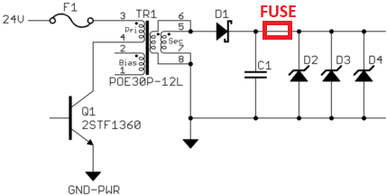
Here is a basic schematic of what I'm considering for the flyback converter and voltage clamp:

The transformer is a Coilcraft POE30P-12L, intended for flyback converters from power over ethernet. The primary is rated for 300 mA, and has inductance of 279 µH.
I'm trying to prove the maximum output current of the transformer, regardless of what might go wrong on the primary side. Power can only be transferred by switching the input, so a shorted or open switch just results in no power.
It seems the theoretical maximum output current is at infinite switching frequency. As infinite input voltage is approached, the duty cycle approaches 0. The worst case should therefore be the input current reflected by the turns ratio, coming out of the secondary continuously.
Let's say F1 is rated for 300 mA, so for IS purposes is assumed to allow 1.7x of that, or 510 mA. The transformer has a turns ratio of 1:0.7 for each of the two secondaries. The same magnetic field caused by 510 mA of input current would therefore require (510 ma)/0.7 = 729 mA of secondary current. It doesn't really matter that both secondaries are in parallel. 729 mA output, no matter how distributed between the two secondaries, results in the same ampere-turns as 510 mA thru the primary.
Let's say that D2-D4 are 6.0 V zeners. For IS purposes, these must be derated by 50%, so we assume they conduct at 9.0 V. (9.0 V)(729 mA) = 6.56 W. Therefore each zener needs to be rated for 6.6 W or more. The 6.56 W doesn't need to be derated again, because it already incorporates the 50% extra rating due to assuming 50% higher voltage.
I can then claim that the output of the clamp is limited to 9.0 V for IS purposes, and that this is therefore the worst case voltage that can be assumed on the left ends of R1 and R2.
Did I get all that right? In particular, is the logic of the maximum output current from the flyback transformer convincing for IS purposes? Is it valid to ignore the input voltage to the transformer, since the current is assumed to not exceed the fuse rating x 1.7? IEC 60079-11 doesn't seem to consider transformers in switching power supplies at all. Is there anything I am missing?
Response to comments
Having seen optocouplers with ATEX certification, not 100% sure you could use POE as an isolation. Is there a reliability calculation requirement?
The only thing I saw in the standard was a requirement for 1.5 kVAC isolation, which this particular POE transformer meets.
Likelihood of F1 not tripping when it should?
This is covered in the standard by derating the fuse to 1.7x its stated trip current. If I use a fuse the manufacturer rates at 300 mA, for example, then it is only considered to interrupt for IS purposes at (300 mA)⋅1.7 = 510 mA.
4 answers
You are accessing this answer with a direct link, so it's being shown above all other answers regardless of its score. You can return to the normal view.
I am also not an expert, but have been working on designing a couple of products that need C1D1, C1D2, and some IS associated apparatus with some electronics consultants that specialize in these certs.
I assumed the zener power calculation would be what you did when designing an IS barrier for a C1D2 main board; however, CSA at least, actually does it like this:
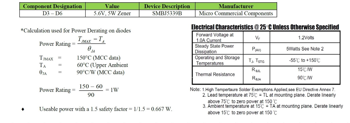
Since you end up with giant expensive Zeners with that math, I ended up using SCR crow bars:
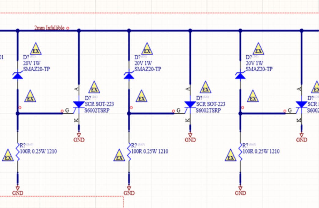
The 2mm thickness on the bold parts is to make them infallible (so they can't short them out for the test from my understanding). Not sure if you ended up going this way, but hopefully this is useful to someone. Can't really show the entire schematic for legal reasons, but I could answer some questions if it would help.
0 comment threads
Disclaimer: I'm not an expert of EX classification myself, but I once was project/product manager for such a project (a zone 0/20 intrinsic control system product). While I can't answer the question directly since my product contained no transformers nor flyback regulators, I can share some related experience.
The tricky part of EX is that one has to think in temperature rather than voltages and currents. So while one can reason about max currents and power in a certain part of the circuit, what's really relevant is how much heat this corresponds to in a certain location. So even if you can theoretically guarantee a maximum current somewhere, it's all about how much heat that maximum current generates at a certain component. A thermographic camera is great for practical experiments here (and awesome for troubleshooting PCBs in general).
The main safety measure we used was to mould the whole PCB inside a plastic material with good thermal characteristics. This caused all heat to spread far more evenly across the product, both during failures and normal operation. For conformance purposes this also made it easier to reason about the PCB as one single component rather than hundreds of components.
We reasoned that a short at any random location of the PCB could cause a current rush that would manifest itself as heat building in the voltage regulator before anywhere else. It is correct that resistors can be regarded as safe since they fail open, so what we did for extra safety was to use low <1 ohm resistors both for the purpose to act as fuses and for spreading heat more evenly. We placed them in series with every voltage regulator in the product (the product contained both switched boost, switched buck and some LDOs), so that an unexpected current rush in a regulator caused by a short in the circuits supplied by it wouldn't cause excessive heat.
To test it all we introduced shorts at certain locations while observing the heat across the moulded PCB with thermographic cameras and ensured that it was kept well-below the classified limit (T=85 dgr C I think it was).
Regarding the zener diodes, I suspect that you need the same "zener barrier" circuit with 3 zener (3 are required for zone 0/20), 1 series resistor and 1 fuse (I think the fuse is optional) in series towards the sensors (P1) that are located in the hazardous zone.
1 comment thread
Please let me know if there is anything wrong with this logic.
So far so good. The voltage clamp (3 zener diodes for European IS category iA and two for category iB) is the limiter on voltage and, providing you do not generate more then these zeners, it's virtually a rubber stamp job. It's likely you are going to be involved with North American standard but, they are similar. If you want to make comparisons I once found this wall-chart quite comforting when I was designing IS stuff (many projects over many years): -
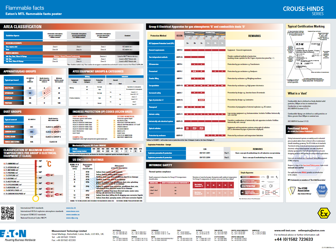
It can be downloaded from here.
For the zener barrier I'm fairly certain that you will need a fuse here: -
In particular, is the logic of the maximum output current from the flyback transformer convincing for IS purposes?
No, use an extra fuse is my advice as per the modified diagram.
I think you are over complicating your thinking a little bit. For an associated device the only thing that matters is how you limit the energy going into the hazardous area. You put your zener barrier with a fuse on the lines connections going to the sense elements. You have to account for losses and the resistance of the fuse in your sensing algorithm, but the protection argument is really simple at that point.
2 comment threads

2 comment threads