Post History
I have a 30MHz TCXO circuit (TCXO datasheet) like this serving as local oscillator to a RFIC: The RFIC manufacturer recommends to "add filtering caps" for high RF output cases. That is >20d...
#4: Post edited
by
 Lorenzo Donati
·
2023-08-13T11:16:59Z (almost 2 years ago)
Lorenzo Donati
·
2023-08-13T11:16:59Z (almost 2 years ago)
Typos. Added relevant tag.
How to calculate the RC filter of a TXCO for a RFIC reference?
- How to calculate the RC filter of a TCXO for a RFIC reference?
I have a 30MHz TCXO circuit ([TXCO datasheet](https://www.jauch.com/downloadfile/57ff72aa49d66_dc1704d8fa28afa2ca8a/jt53l.pdf)) like this serving as local oscillator to a RFIC:- 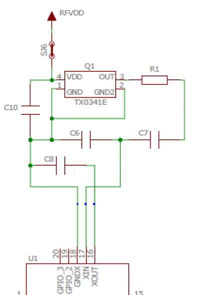
- ---
- The RFIC manufacturer recommends to "add filtering caps" for high RF output cases. That is >20dBm, after which I suppose they are concerned that the fundamental signal radiates back into the oscillator traces. Specifically, one AN says:
- > _in the high output power cases_ (+20 dBm or higher), it is recommended to use additional filtering sections in order to achieve larger suppression at the reference spurs. These additional filter sections contain a grounding capacitor to the XOUT and an RC filter from the TCXO output to the input of XIN. It only makes sense when the goal is to comply with the ETSI Category 1 EMC regulation within acceptable margins.
- I do need this ETSI Category 1 (they mean EN/ETSI 300 220-1 for sub-GHz short range devices) which specifies certain limits on blocking, minimum adjacent channel selectivity, spurious response rejection and so on.
- They say that component values should be chosen based on frequency band, which I assume means a suitable cut-off frequency for the RF carrier. They call this a "RC filter" although it isn't a conventional low pass circuit with a single cap to ground, in which case I'd just do 1/2πRC.
- Questions:
- - How do I pick the values of R1 and C7 given a certain cut-off frequency (say for example 500MHz)?
- - What is the purpose of C7, is actually part of the filter or is it only there for blocking purposes? Why isn't it sitting towards ground?
- I'm assuming C6 and C8 are just load caps for the oscillator and should be 10pF or so.
- I have a 30MHz TCXO circuit ([TCXO datasheet](https://www.jauch.com/downloadfile/57ff72aa49d66_dc1704d8fa28afa2ca8a/jt53l.pdf)) like this serving as local oscillator to a RFIC:
- 
- ---
- The RFIC manufacturer recommends to "add filtering caps" for high RF output cases. That is >20dBm, after which I suppose they are concerned that the fundamental signal radiates back into the oscillator traces. Specifically, one AN says:
- > _in the high output power cases_ (+20 dBm or higher), it is recommended to use additional filtering sections in order to achieve larger suppression at the reference spurs. These additional filter sections contain a grounding capacitor to the XOUT and an RC filter from the TCXO output to the input of XIN. It only makes sense when the goal is to comply with the ETSI Category 1 EMC regulation within acceptable margins.
- I do need this ETSI Category 1 (they mean EN/ETSI 300 220-1 for sub-GHz short range devices) which specifies certain limits on blocking, minimum adjacent channel selectivity, spurious response rejection and so on.
- They say that component values should be chosen based on frequency band, which I assume means a suitable cut-off frequency for the RF carrier. They call this a "RC filter" although it isn't a conventional low pass circuit with a single cap to ground, in which case I'd just do 1/2πRC.
- Questions:
- - How do I pick the values of R1 and C7 given a certain cut-off frequency (say for example 500MHz)?
- - What is the purpose of C7, is actually part of the filter or is it only there for blocking purposes? Why isn't it sitting towards ground?
- I'm assuming C6 and C8 are just load caps for the oscillator and should be 10pF or so.
#3: Post edited
by
 Lundin
·
2022-01-26T07:34:48Z (over 3 years ago)
Lundin
·
2022-01-26T07:34:48Z (over 3 years ago)
- I have a 30MHz TCXO circuit ([TXCO datasheet](https://www.jauch.com/downloadfile/57ff72aa49d66_dc1704d8fa28afa2ca8a/jt53l.pdf)) like this serving as local oscillator to a RFIC:
- 
- ---
The RFIC manufacturer recommends to "add filtering caps" for high RF output cases. That is >20dBm, after which I suppose they are concerned that the fundamental signal radiates back into the oscillator traces. They say that component values should be chosen based on frequency band, which I assume means a suitable cut-off frequency for the RF carrier. They call this a "RC filter" although it isn't a conventional low pass circuit with a single cap to ground, in which case I'd just do 1/2πRC.- Questions:
- - How do I pick the values of R1 and C7 given a certain cut-off frequency (say for example 500MHz)?
- - What is the purpose of C7, is actually part of the filter or is it only there for blocking purposes? Why isn't it sitting towards ground?
- I'm assuming C6 and C8 are just load caps for the oscillator and should be 10pF or so.
- I have a 30MHz TCXO circuit ([TXCO datasheet](https://www.jauch.com/downloadfile/57ff72aa49d66_dc1704d8fa28afa2ca8a/jt53l.pdf)) like this serving as local oscillator to a RFIC:
- 
- ---
- The RFIC manufacturer recommends to "add filtering caps" for high RF output cases. That is >20dBm, after which I suppose they are concerned that the fundamental signal radiates back into the oscillator traces. Specifically, one AN says:
- > _in the high output power cases_ (+20 dBm or higher), it is recommended to use additional filtering sections in order to achieve larger suppression at the reference spurs. These additional filter sections contain a grounding capacitor to the XOUT and an RC filter from the TCXO output to the input of XIN. It only makes sense when the goal is to comply with the ETSI Category 1 EMC regulation within acceptable margins.
- I do need this ETSI Category 1 (they mean EN/ETSI 300 220-1 for sub-GHz short range devices) which specifies certain limits on blocking, minimum adjacent channel selectivity, spurious response rejection and so on.
- They say that component values should be chosen based on frequency band, which I assume means a suitable cut-off frequency for the RF carrier. They call this a "RC filter" although it isn't a conventional low pass circuit with a single cap to ground, in which case I'd just do 1/2πRC.
- Questions:
- - How do I pick the values of R1 and C7 given a certain cut-off frequency (say for example 500MHz)?
- - What is the purpose of C7, is actually part of the filter or is it only there for blocking purposes? Why isn't it sitting towards ground?
- I'm assuming C6 and C8 are just load caps for the oscillator and should be 10pF or so.
#2: Post edited
by
Lundin
·
2022-01-26T07:26:03Z (over 3 years ago)
- I have a 30MHz TCXO circuit ([TXCO datasheet](https://www.jauch.com/downloadfile/57ff72aa49d66_dc1704d8fa28afa2ca8a/jt53l.pdf)) like this serving as local oscillator to a RFIC:
- 
- ---
The RFIC manufacturer recommends to "add filtering caps" for high RF output cases. They say that component values should be chosen based on frequency band, which I assume means a suitable cut-off frequency for the RF carrier. They call this a "RC filter" although it isn't a conventional low pass circuit with a single cap to ground, in which case I'd just do 1/2πRC.- Questions:
- - How do I pick the values of R1 and C7 given a certain cut-off frequency (say for example 500MHz)?
- - What is the purpose of C7, is actually part of the filter or is it only there for blocking purposes? Why isn't it sitting towards ground?
- I'm assuming C6 and C8 are just load caps for the oscillator and should be 10pF or so.
- I have a 30MHz TCXO circuit ([TXCO datasheet](https://www.jauch.com/downloadfile/57ff72aa49d66_dc1704d8fa28afa2ca8a/jt53l.pdf)) like this serving as local oscillator to a RFIC:
- 
- ---
- The RFIC manufacturer recommends to "add filtering caps" for high RF output cases. That is >20dBm, after which I suppose they are concerned that the fundamental signal radiates back into the oscillator traces. They say that component values should be chosen based on frequency band, which I assume means a suitable cut-off frequency for the RF carrier. They call this a "RC filter" although it isn't a conventional low pass circuit with a single cap to ground, in which case I'd just do 1/2πRC.
- Questions:
- - How do I pick the values of R1 and C7 given a certain cut-off frequency (say for example 500MHz)?
- - What is the purpose of C7, is actually part of the filter or is it only there for blocking purposes? Why isn't it sitting towards ground?
- I'm assuming C6 and C8 are just load caps for the oscillator and should be 10pF or so.
#1: Initial revision
by
Lundin
·
2022-01-25T14:24:59Z (over 3 years ago)
How to calculate the RC filter of a TXCO for a RFIC reference?
I have a 30MHz TCXO circuit ([TXCO datasheet](https://www.jauch.com/downloadfile/57ff72aa49d66_dc1704d8fa28afa2ca8a/jt53l.pdf)) like this serving as local oscillator to a RFIC:  --- The RFIC manufacturer recommends to "add filtering caps" for high RF output cases. They say that component values should be chosen based on frequency band, which I assume means a suitable cut-off frequency for the RF carrier. They call this a "RC filter" although it isn't a conventional low pass circuit with a single cap to ground, in which case I'd just do 1/2πRC. Questions: - How do I pick the values of R1 and C7 given a certain cut-off frequency (say for example 500MHz)? - What is the purpose of C7, is actually part of the filter or is it only there for blocking purposes? Why isn't it sitting towards ground? I'm assuming C6 and C8 are just load caps for the oscillator and should be 10pF or so.