Post History
I was watching a video from EEVBLOG about bypass capacitors, and he presented a theory that randomly connecting different values of capacitors in parallel can create unexpected impedance spikes: ...
#5: Post edited
by
 Elleanor Lopez
·
2022-06-01T07:18:49Z (about 3 years ago)
Elleanor Lopez
·
2022-06-01T07:18:49Z (about 3 years ago)
- I was watching a [video](https://youtu.be/BcJ6UdDx1vg?t=1611) from EEVBLOG about bypass capacitors, and he presented a theory that randomly connecting different values of capacitors in parallel can create unexpected impedance spikes:
- 
- However, he did not explain why the spike is there. Thinking about it some more, I could not come up with an explanation other than bad test setup. Resistance and inductance go down as more values are added in parallel. Although total capacitance goes up, which would lower the total resonance frequency, 110nF in relation to 10uF cannot cause such a drastic shift.
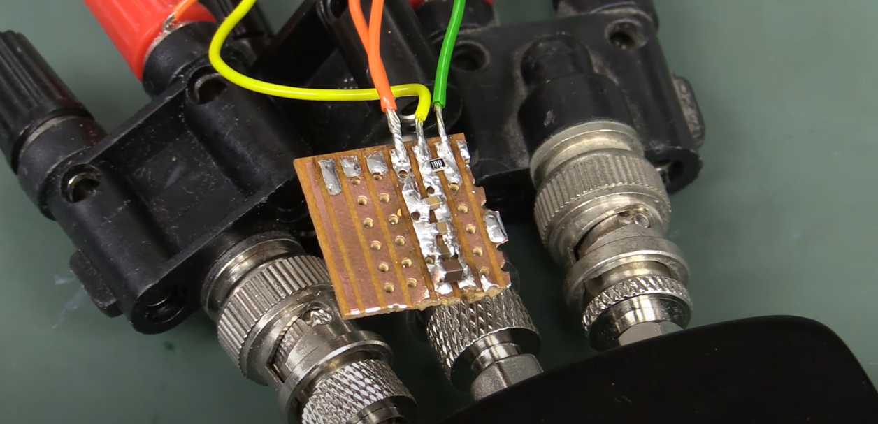
- This was his test setup:
- 
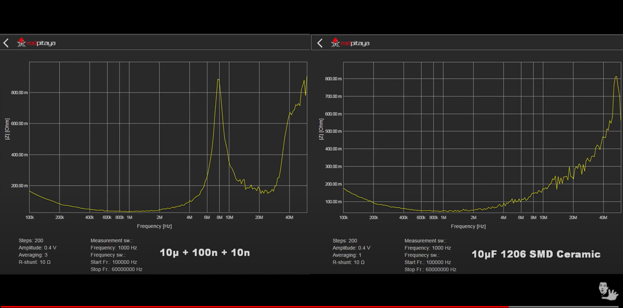
To inspect the picture, right click and open in new tab, the scales are then visible. Regardless:The frequency scale is logarithmic, impedance scale is linear. Both graphs have 100kHz-40MHz frequency range, and the spike on the left side is located at 8Mhz point, reaching ~800mOhm impedance.- I assume that the solder blobs between capacitors introduced a series inductance that in turn caused the spike in impedance at 8MHz.
- Could that be the case, or is there something else that could cause the spike?
- I was watching a [video](https://youtu.be/BcJ6UdDx1vg?t=1611) from EEVBLOG about bypass capacitors, and he presented a theory that randomly connecting different values of capacitors in parallel can create unexpected impedance spikes:
- 
- To inspect the picture, right click and open in new tab, the scales are then visible. Regardless:
- The frequency scale is logarithmic, impedance scale is linear. Both graphs have 100kHz-40MHz frequency range, and the spike on the left side is located at 8Mhz point, reaching ~800mOhm impedance.
- However, he did not explain why the spike is there. Thinking about it some more, I could not come up with an explanation other than bad test setup. Resistance and inductance go down as more values are added in parallel. Although total capacitance goes up, which would lower the total resonance frequency, 110nF in relation to 10uF cannot cause such a drastic shift.
- This was his test setup:
- 
- I assume that the solder blobs between capacitors introduced a series inductance that in turn caused the spike in impedance at 8MHz.
- Could that be the case, or is there something else that could cause the spike?
#4: Post edited
by
Elleanor Lopez
·
2022-06-01T07:18:30Z (about 3 years ago)
Described the axis
- I was watching a [video](https://youtu.be/BcJ6UdDx1vg?t=1611) from EEVBLOG about bypass capacitors, and he presented a theory that randomly connecting different values of capacitors in parallel can create unexpected impedance spikes:
- 
- However, he did not explain why the spike is there. Thinking about it some more, I could not come up with an explanation other than bad test setup. Resistance and inductance go down as more values are added in parallel. Although total capacitance goes up, which would lower the total resonance frequency, 110nF in relation to 10uF cannot cause such a drastic shift.
- This was his test setup:
- 
- I assume that the solder blobs between capacitors introduced a series inductance that in turn caused the spike in impedance at 8MHz.
- Could that be the case, or is there something else that could cause the spike?
- I was watching a [video](https://youtu.be/BcJ6UdDx1vg?t=1611) from EEVBLOG about bypass capacitors, and he presented a theory that randomly connecting different values of capacitors in parallel can create unexpected impedance spikes:
- 
- However, he did not explain why the spike is there. Thinking about it some more, I could not come up with an explanation other than bad test setup. Resistance and inductance go down as more values are added in parallel. Although total capacitance goes up, which would lower the total resonance frequency, 110nF in relation to 10uF cannot cause such a drastic shift.
- This was his test setup:
- 
- To inspect the picture, right click and open in new tab, the scales are then visible. Regardless:
- The frequency scale is logarithmic, impedance scale is linear. Both graphs have 100kHz-40MHz frequency range, and the spike on the left side is located at 8Mhz point, reaching ~800mOhm impedance.
- I assume that the solder blobs between capacitors introduced a series inductance that in turn caused the spike in impedance at 8MHz.
- Could that be the case, or is there something else that could cause the spike?
#3: Post edited
by
 Lundin
·
2022-06-01T06:46:26Z (about 3 years ago)
Lundin
·
2022-06-01T06:46:26Z (about 3 years ago)
#2: Post edited
by
Elleanor Lopez
·
2022-05-31T08:43:47Z (about 3 years ago)
- I was watching a [video](https://youtu.be/BcJ6UdDx1vg?t=1611) from EEVBLOG about bypass capacitors, and he presented a theory that randomly connecting different values of capacitors in parallel can create unexpected impedance spikes:
- 
- However, he did not explain why the spike is there. Thinking about it some more, I could not come up with an explanation other than bad test setup. Resistance and inductance go down as more values are added in parallel. Although total capacitance goes up, which would lower the total resonance frequency, 110nF in relation to 10uF cannot cause such a drastic shift.
- This was his test setup:
- 
I assume that the solder blobs between capacitors introduced a series impedance that in turn caused the spike in impedance at 8MHz.- Could that be the case, or is there something else that could cause the spike?
- I was watching a [video](https://youtu.be/BcJ6UdDx1vg?t=1611) from EEVBLOG about bypass capacitors, and he presented a theory that randomly connecting different values of capacitors in parallel can create unexpected impedance spikes:
- 
- However, he did not explain why the spike is there. Thinking about it some more, I could not come up with an explanation other than bad test setup. Resistance and inductance go down as more values are added in parallel. Although total capacitance goes up, which would lower the total resonance frequency, 110nF in relation to 10uF cannot cause such a drastic shift.
- This was his test setup:
- 
- I assume that the solder blobs between capacitors introduced a series inductance that in turn caused the spike in impedance at 8MHz.
- Could that be the case, or is there something else that could cause the spike?
#1: Initial revision
by
Elleanor Lopez
·
2022-05-31T08:42:40Z (about 3 years ago)
Unexpected impedance spike when paralleling capacitors
I was watching a [video](https://youtu.be/BcJ6UdDx1vg?t=1611) from EEVBLOG about bypass capacitors, and he presented a theory that randomly connecting different values of capacitors in parallel can create unexpected impedance spikes:  However, he did not explain why the spike is there. Thinking about it some more, I could not come up with an explanation other than bad test setup. Resistance and inductance go down as more values are added in parallel. Although total capacitance goes up, which would lower the total resonance frequency, 110nF in relation to 10uF cannot cause such a drastic shift. This was his test setup:  I assume that the solder blobs between capacitors introduced a series impedance that in turn caused the spike in impedance at 8MHz. Could that be the case, or is there something else that could cause the spike?