Post History
I think you can make a pretty good case for the spike being caused by the addition of the 100n and 10n capacitors: - I assume that the solder blobs between capacitors introduced a series indu...
#1: Initial revision
by
 Andy aka
·
2022-06-02T13:40:19Z (almost 3 years ago)
Andy aka
·
2022-06-02T13:40:19Z (almost 3 years ago)
I think you can make a pretty good case for the spike being caused by the addition of the 100n and 10n capacitors: - 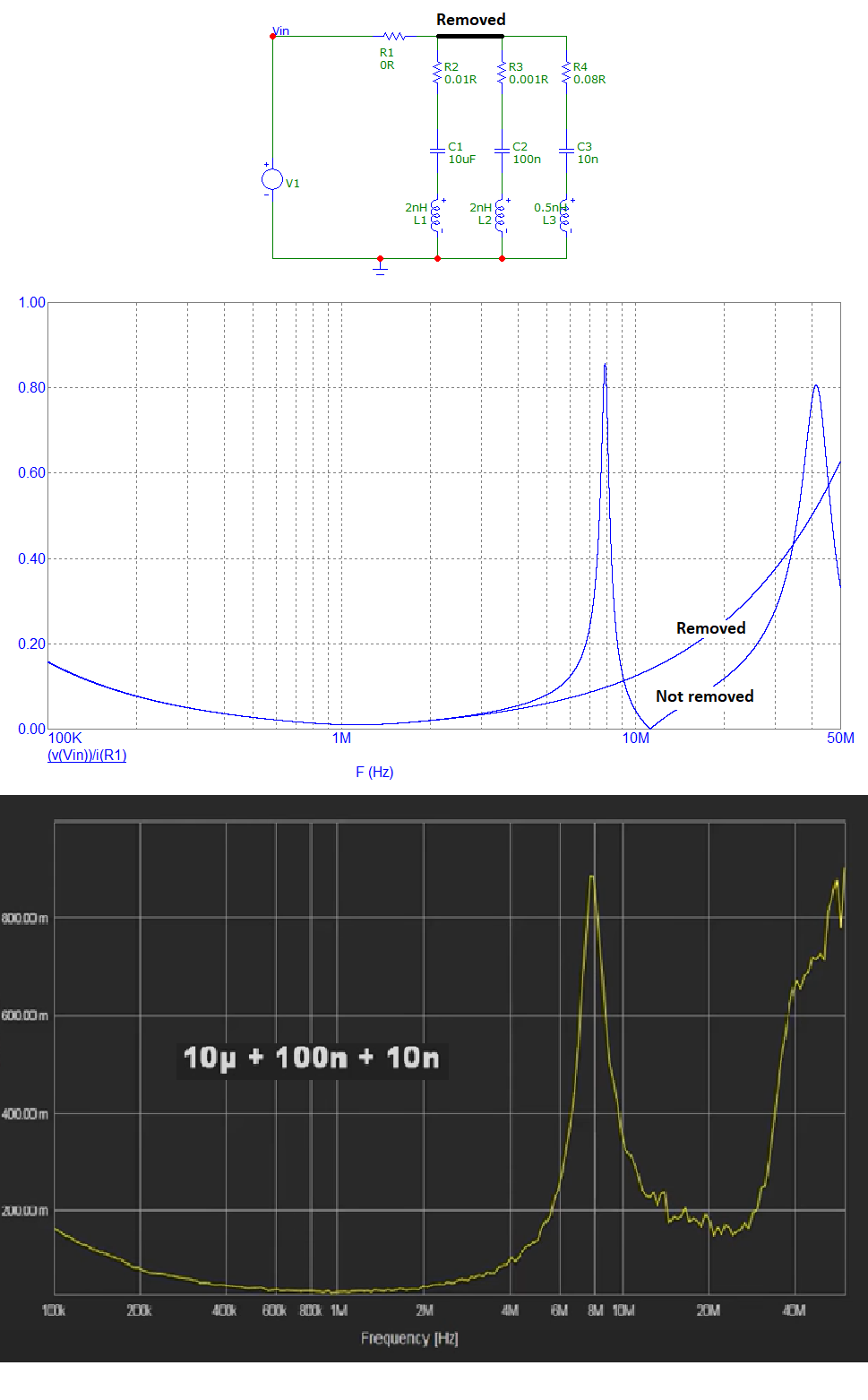 > *I assume that the solder blobs between capacitors introduced a series > inductance that in turn caused the spike in impedance at 8MHz.* It can't be ruled out but neither can the inductance of the yellow, orange and green wires on the test set-up. I mean, where do they go and what effect do they have I wonder?