Post History
This LC circuit depends on several criteria for stable linear oscillation; 180 deg phase shift ( with 3rd order LC network) plus 180 degree inversion to achieve the oscillation criteria of 0 or ...
#9: Post edited
by
 TonyStewart
·
2022-08-13T15:44:26Z (almost 3 years ago)
TonyStewart
·
2022-08-13T15:44:26Z (almost 3 years ago)
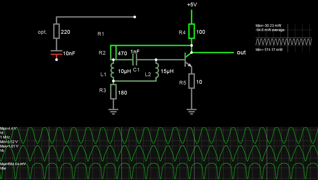
- This LC circuit depends on several criteria for stable linear oscillation;
- - 180 deg phase shift ( with 3rd order LC network) plus 180 degree inversion to achieve the oscillation criteria of 0 or 360 deg at gain >=1 Thus each reactance affects fo.
- - adequate bias current and impedance ratios with negative feedback ratios at DC and at fo.
- - Only 1 capacitor is necessary
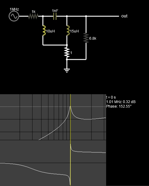
- A variation was made by adding the L1,L2 ground resistance for a notch filter effect.
- - keeping the resistance ratios of R2/R3=1.5 to 3 range that affects feedback attenuation and impedance range used to satisfy requirements.
- - The feedback cap. and H bias were also replaced with one feedback resistor, R2
- - By tuning hFE to lower values, one can improve R ratios for sufficient gain to oscillate with pull up/down for a symmetrical sine wave.
- - Excess gain will clip the sine wave.
- The sensitivity to each resistance part value in the simulation gives more insight than the math and leads to a stable result. In reality, hFE is nonlinear with current, but I did add a slider for constant hFE = 10 to 50.
- The highlight of this answer is to show the results of resistance ratios and hFE can be significant.
- 
- [Falstad Simulation]
- This design is not intended to be ideal, and there are better designs that have much higher Q for square wave clocks or nonlinear feedback for sine amplitude unity-gain AGC-like control.
- https://tinyurl.com/2nu4eyrb

- This LC circuit depends on several criteria for stable linear oscillation;
- - 180 deg phase shift ( with 3rd order LC network) plus 180 degree inversion to achieve the oscillation criteria of 0 or 360 deg at gain >=1 Thus each reactance affects fo.
- - adequate bias current and impedance ratios with negative feedback ratios at DC and at fo.
- - Only 1 capacitor is necessary
- A variation was made by adding the L1,L2 ground resistance for a notch filter effect.
- - keeping the resistance ratios of R2/R3=1.5 to 3 range that affects feedback attenuation and impedance range used to satisfy requirements.
- - The feedback cap. and H bias were also replaced with one feedback resistor, R2
- - By tuning hFE to lower values, one can improve R ratios for sufficient gain to oscillate with pull up/down for a symmetrical sine wave.
- - Excess gain will clip the sine wave.
- The sensitivity to each resistance part value in the simulation gives more insight than the math and leads to a stable result. In reality, hFE is nonlinear with current, but I did add a slider for constant hFE = 10 to 50.
- The highlight of this answer is to show the results of resistance ratios and hFE can be significant.
- 
- [Falstad Simulation]
- This design is not intended to be ideal, and there are better designs that have much higher Q for square wave clocks or nonlinear feedback for sine amplitude unity-gain AGC-like control.
- https://tinyurl.com/2nu4eyrb
- 
#8: Post edited
by
TonyStewart
·
2022-08-13T15:42:16Z (almost 3 years ago)
- This LC circuit depends on several criteria for stable linear oscillation;
- - 180 deg phase shift ( with 3rd order LC network) plus 180 degree inversion to achieve the oscillation criteria of 0 or 360 deg at gain >=1 Thus each reactance affects fo.
- - adequate bias current and impedance ratios with negative feedback ratios at DC and at fo.
- - Only 1 capacitor is necessary
- A variation was made by adding the L1,L2 ground resistance for a notch filter effect.
- - keeping the resistance ratios of R2/R3=1.5 to 3 range that affects feedback attenuation and impedance range used to satisfy requirements.
- - The feedback cap. and H bias were also replaced with one feedback resistor, R2
- - By tuning hFE to lower values, one can improve R ratios for sufficient gain to oscillate with pull up/down for a symmetrical sine wave.
- - Excess gain will clip the sine wave.
- The sensitivity to each resistance part value in the simulation gives more insight than the math and leads to a stable result. In reality, hFE is nonlinear with current, but I did add a slider for constant hFE = 10 to 50.
- The highlight of this answer is to show the results of resistance ratios and hFE can be significant.
- 
- [Falstad Simulation]
- This design is not intended to be ideal, and there are better designs that have much higher Q for square wave clocks or nonlinear feedback for sine amplitude unity-gain AGC-like control.
https://tinyurl.com/2nu4eyrb
- This LC circuit depends on several criteria for stable linear oscillation;
- - 180 deg phase shift ( with 3rd order LC network) plus 180 degree inversion to achieve the oscillation criteria of 0 or 360 deg at gain >=1 Thus each reactance affects fo.
- - adequate bias current and impedance ratios with negative feedback ratios at DC and at fo.
- - Only 1 capacitor is necessary
- A variation was made by adding the L1,L2 ground resistance for a notch filter effect.
- - keeping the resistance ratios of R2/R3=1.5 to 3 range that affects feedback attenuation and impedance range used to satisfy requirements.
- - The feedback cap. and H bias were also replaced with one feedback resistor, R2
- - By tuning hFE to lower values, one can improve R ratios for sufficient gain to oscillate with pull up/down for a symmetrical sine wave.
- - Excess gain will clip the sine wave.
- The sensitivity to each resistance part value in the simulation gives more insight than the math and leads to a stable result. In reality, hFE is nonlinear with current, but I did add a slider for constant hFE = 10 to 50.
- The highlight of this answer is to show the results of resistance ratios and hFE can be significant.
- 
- [Falstad Simulation]
- This design is not intended to be ideal, and there are better designs that have much higher Q for square wave clocks or nonlinear feedback for sine amplitude unity-gain AGC-like control.
- https://tinyurl.com/2nu4eyrb
- 
#7: Post edited
by
TonyStewart
·
2022-08-13T15:40:10Z (almost 3 years ago)
- This LC circuit depends on several criteria for stable linear oscillation;
- - 180 deg phase shift ( with 3rd order LC network) plus 180 degree inversion to achieve the oscillation criteria of 0 or 360 deg at gain >=1 Thus each reactance affects fo.
- - adequate bias current and impedance ratios with negative feedback ratios at DC and at fo.
- - Only 1 capacitor is necessary
- A variation was made by adding the L1,L2 ground resistance for a notch filter effect.
- - keeping the resistance ratios of R2/R3=1.5 to 3 range that affects feedback attenuation and impedance range used to satisfy requirements.
- - The feedback cap. and H bias were also replaced with one feedback resistor, R2
- - By tuning hFE to lower values, one can improve R ratios for sufficient gain to oscillate with pull up/down for a symmetrical sine wave.
- - Excess gain will clip the sine wave.
- The sensitivity to each resistance part value in the simulation gives more insight than the math and leads to a stable result. In reality, hFE is nonlinear with current, but I did add a slider for constant hFE = 10 to 50.
- The highlight of this answer is to show the results of resistance ratios and hFE can be significant.
- 
- [Falstad Simulation]
This design is not intended to be ideal, and there are better designs.- https://tinyurl.com/2nu4eyrb
- This LC circuit depends on several criteria for stable linear oscillation;
- - 180 deg phase shift ( with 3rd order LC network) plus 180 degree inversion to achieve the oscillation criteria of 0 or 360 deg at gain >=1 Thus each reactance affects fo.
- - adequate bias current and impedance ratios with negative feedback ratios at DC and at fo.
- - Only 1 capacitor is necessary
- A variation was made by adding the L1,L2 ground resistance for a notch filter effect.
- - keeping the resistance ratios of R2/R3=1.5 to 3 range that affects feedback attenuation and impedance range used to satisfy requirements.
- - The feedback cap. and H bias were also replaced with one feedback resistor, R2
- - By tuning hFE to lower values, one can improve R ratios for sufficient gain to oscillate with pull up/down for a symmetrical sine wave.
- - Excess gain will clip the sine wave.
- The sensitivity to each resistance part value in the simulation gives more insight than the math and leads to a stable result. In reality, hFE is nonlinear with current, but I did add a slider for constant hFE = 10 to 50.
- The highlight of this answer is to show the results of resistance ratios and hFE can be significant.
- 
- [Falstad Simulation]
- This design is not intended to be ideal, and there are better designs that have much higher Q for square wave clocks or nonlinear feedback for sine amplitude unity-gain AGC-like control.
- https://tinyurl.com/2nu4eyrb
#6: Post edited
by
TonyStewart
·
2022-08-13T15:38:30Z (almost 3 years ago)
- This LC circuit depends on several criteria for stable linear oscillation;
- - 180 deg phase shift ( with 3rd order LC network) plus 180 degree inversion to achieve the oscillation criteria of 0 or 360 deg at gain >=1 Thus each reactance affects fo.
- - adequate bias current and impedance ratios with negative feedback ratios at DC and at fo.
- - Only 1 capacitor is necessary
- A variation was made by adding the L1,L2 ground resistance for a notch filter effect.
- - keeping the resistance ratios of R2/R3=1.5 to 3 range that affects feedback attenuation and impedance range used to satisfy requirements.
- - The feedback cap. and H bias were also replaced with one feedback resistor, R2
- - By tuning hFE to lower values, one can improve R ratios for sufficient gain to oscillate with pull up/down for a symmetrical sine wave.
- - Excess gain will clip the sine wave.
- The sensitivity to each resistance part value in the simulation gives more insight than the math and leads to a stable result. In reality, hFE is nonlinear with current, but I did add a slider for constant hFE = 10 to 50.
- The highlight of this answer is to show the results of resistance ratios and hFE can be significant.
- 
- [Falstad Simulation]
- https://tinyurl.com/2nu4eyrb
- This LC circuit depends on several criteria for stable linear oscillation;
- - 180 deg phase shift ( with 3rd order LC network) plus 180 degree inversion to achieve the oscillation criteria of 0 or 360 deg at gain >=1 Thus each reactance affects fo.
- - adequate bias current and impedance ratios with negative feedback ratios at DC and at fo.
- - Only 1 capacitor is necessary
- A variation was made by adding the L1,L2 ground resistance for a notch filter effect.
- - keeping the resistance ratios of R2/R3=1.5 to 3 range that affects feedback attenuation and impedance range used to satisfy requirements.
- - The feedback cap. and H bias were also replaced with one feedback resistor, R2
- - By tuning hFE to lower values, one can improve R ratios for sufficient gain to oscillate with pull up/down for a symmetrical sine wave.
- - Excess gain will clip the sine wave.
- The sensitivity to each resistance part value in the simulation gives more insight than the math and leads to a stable result. In reality, hFE is nonlinear with current, but I did add a slider for constant hFE = 10 to 50.
- The highlight of this answer is to show the results of resistance ratios and hFE can be significant.
- 
- [Falstad Simulation]
- This design is not intended to be ideal, and there are better designs.
- https://tinyurl.com/2nu4eyrb
#5: Post edited
by
TonyStewart
·
2022-08-13T15:21:00Z (almost 3 years ago)
- This LC circuit depends on several criteria for stable linear oscillation;
- 180 deg phase shift plus 180 degree inversion- - adequate bias current and impedance ratios with negative feedback ratios at DC and at fo.
- - Only 1 capacitor is necessary
- A variation was made by adding the L1,L2 ground resistance for a notch filter effect.
- - keeping the resistance ratios of R2/R3=1.5 to 3 range that affects feedback attenuation and impedance range used to satisfy requirements.
- - The feedback cap. and H bias were also replaced with one feedback resistor, R2
- - By tuning hFE to lower values, one can improve R ratios for sufficient gain to oscillate with pull up/down for a symmetrical sine wave.
- - Excess gain will clip the sine wave.
- The sensitivity to each resistance part value in the simulation gives more insight than the math and leads to a stable result. In reality, hFE is nonlinear with current, but I did add a slider for constant hFE = 10 to 50.
- The highlight of this answer is to show the results of resistance ratios and hFE can be significant.
- 
- [Falstad Simulation]
- https://tinyurl.com/2nu4eyrb
- This LC circuit depends on several criteria for stable linear oscillation;
- - 180 deg phase shift ( with 3rd order LC network) plus 180 degree inversion to achieve the oscillation criteria of 0 or 360 deg at gain >=1 Thus each reactance affects fo.
- - adequate bias current and impedance ratios with negative feedback ratios at DC and at fo.
- - Only 1 capacitor is necessary
- A variation was made by adding the L1,L2 ground resistance for a notch filter effect.
- - keeping the resistance ratios of R2/R3=1.5 to 3 range that affects feedback attenuation and impedance range used to satisfy requirements.
- - The feedback cap. and H bias were also replaced with one feedback resistor, R2
- - By tuning hFE to lower values, one can improve R ratios for sufficient gain to oscillate with pull up/down for a symmetrical sine wave.
- - Excess gain will clip the sine wave.
- The sensitivity to each resistance part value in the simulation gives more insight than the math and leads to a stable result. In reality, hFE is nonlinear with current, but I did add a slider for constant hFE = 10 to 50.
- The highlight of this answer is to show the results of resistance ratios and hFE can be significant.
- 
- [Falstad Simulation]
- https://tinyurl.com/2nu4eyrb
#4: Post edited
by
TonyStewart
·
2022-08-13T07:38:56Z (almost 3 years ago)
- This LC circuit depends on several criteria for stable linear oscillation;
- - 180 deg phase shift plus 180 degree inversion
- - adequate bias current and impedance ratios with negative feedback ratios at DC and at fo.
- - Only 1 capacitor is necessary
An improvement was made adding the L1,L2 ground resistance for a deeper notch effect.- - keeping the resistance ratios of R2/R3=1.5 to 3 range that affects feedback attenuation and impedance range used to satisfy requirements.
- - The feedback cap. and H bias were also replaced with one feedback resistor, R2
- - By tuning hFE to lower values, one can improve R ratios for sufficient gain to oscillate with pull up/down for a symmetrical sine wave.
- - Excess gain will clip the sine wave.
- The sensitivity to each resistance part value in the simulation gives more insight than the math and leads to a stable result. In reality, hFE is nonlinear with current, but I did add a slider for constant hFE = 10 to 50.
- 
- [Falstad Simulation]
- https://tinyurl.com/2nu4eyrb
- This LC circuit depends on several criteria for stable linear oscillation;
- - 180 deg phase shift plus 180 degree inversion
- - adequate bias current and impedance ratios with negative feedback ratios at DC and at fo.
- - Only 1 capacitor is necessary
- A variation was made by adding the L1,L2 ground resistance for a notch filter effect.
- - keeping the resistance ratios of R2/R3=1.5 to 3 range that affects feedback attenuation and impedance range used to satisfy requirements.
- - The feedback cap. and H bias were also replaced with one feedback resistor, R2
- - By tuning hFE to lower values, one can improve R ratios for sufficient gain to oscillate with pull up/down for a symmetrical sine wave.
- - Excess gain will clip the sine wave.
- The sensitivity to each resistance part value in the simulation gives more insight than the math and leads to a stable result. In reality, hFE is nonlinear with current, but I did add a slider for constant hFE = 10 to 50.
- The highlight of this answer is to show the results of resistance ratios and hFE can be significant.
- 
- [Falstad Simulation]
- https://tinyurl.com/2nu4eyrb
#3: Post edited
by
TonyStewart
·
2022-08-13T07:24:03Z (almost 3 years ago)
- This LC circuit depends on several criteria for stable linear oscillation;
- - 180 deg phase shift plus 180 degree inversion
- - adequate bias current and impedance ratios with negative feedback ratios at DC and at fo.
- - Only 1 capacitor is necessary
- An improvement was made adding the L1,L2 ground resistance for a deeper notch effect.
- - keeping the resistance ratios of R2/R3=1.5 to 3 range that affects feedback attenuation and impedance range used to satisfy requirements.
- - The feedback cap. and H bias were also replaced with one feedback resistor, R2
- - By tuning hFE to lower values, one can improve R ratios for sufficient gain to oscillate with pull up/down for a symmetrical sine wave.
- - Excess gain will clip the sine wave.
The sensitivity to each resistance part value in the simulation gives more insight than the math and leads to a stable result. In reality, hFE is nonlinear with current, but I did add a slider for constant hFE.- 
- [Falstad Simulation]
- https://tinyurl.com/2nu4eyrb
- This LC circuit depends on several criteria for stable linear oscillation;
- - 180 deg phase shift plus 180 degree inversion
- - adequate bias current and impedance ratios with negative feedback ratios at DC and at fo.
- - Only 1 capacitor is necessary
- An improvement was made adding the L1,L2 ground resistance for a deeper notch effect.
- - keeping the resistance ratios of R2/R3=1.5 to 3 range that affects feedback attenuation and impedance range used to satisfy requirements.
- - The feedback cap. and H bias were also replaced with one feedback resistor, R2
- - By tuning hFE to lower values, one can improve R ratios for sufficient gain to oscillate with pull up/down for a symmetrical sine wave.
- - Excess gain will clip the sine wave.
- The sensitivity to each resistance part value in the simulation gives more insight than the math and leads to a stable result. In reality, hFE is nonlinear with current, but I did add a slider for constant hFE = 10 to 50.
- 
- [Falstad Simulation]
- https://tinyurl.com/2nu4eyrb
#2: Post edited
by
TonyStewart
·
2022-08-13T07:23:25Z (almost 3 years ago)
- This LC circuit depends on several criteria for stable linear oscillation;
- - 180 deg phase shift plus 180 degree inversion
- - adequate bias current and impedance ratios with negative feedback ratios at DC and at fo.
- - Only 1 capacitor is necessary
- An improvement was made adding the L1,L2 ground resistance for a deeper notch effect.
- - keeping the resistance ratios of R2/R3=1.5 to 3 range that affects feedback attenuation and impedance range used to satisfy requirements.
- - The feedback cap. and H bias were also replaced with one feedback resistor, R2
- - By tuning hFE to lower values, one can improve R ratios for sufficient gain to oscillate with pull up/down for a symmetrical sine wave.
- - Excess gain will clip the sine wave.
- The sensitivity to each resistance part value in the simulation gives more insight than the math and leads to a stable result. In reality, hFE is nonlinear with current, but I did add a slider for constant hFE.
- [Falstad Simulation]
- https://tinyurl.com/2nu4eyrb
- This LC circuit depends on several criteria for stable linear oscillation;
- - 180 deg phase shift plus 180 degree inversion
- - adequate bias current and impedance ratios with negative feedback ratios at DC and at fo.
- - Only 1 capacitor is necessary
- An improvement was made adding the L1,L2 ground resistance for a deeper notch effect.
- - keeping the resistance ratios of R2/R3=1.5 to 3 range that affects feedback attenuation and impedance range used to satisfy requirements.
- - The feedback cap. and H bias were also replaced with one feedback resistor, R2
- - By tuning hFE to lower values, one can improve R ratios for sufficient gain to oscillate with pull up/down for a symmetrical sine wave.
- - Excess gain will clip the sine wave.
- The sensitivity to each resistance part value in the simulation gives more insight than the math and leads to a stable result. In reality, hFE is nonlinear with current, but I did add a slider for constant hFE.
- 
- [Falstad Simulation]
- https://tinyurl.com/2nu4eyrb
#1: Initial revision
by
TonyStewart
·
2022-08-13T07:22:38Z (almost 3 years ago)
This LC circuit depends on several criteria for stable linear oscillation; - 180 deg phase shift plus 180 degree inversion - adequate bias current and impedance ratios with negative feedback ratios at DC and at fo. - Only 1 capacitor is necessary An improvement was made adding the L1,L2 ground resistance for a deeper notch effect. - keeping the resistance ratios of R2/R3=1.5 to 3 range that affects feedback attenuation and impedance range used to satisfy requirements. - The feedback cap. and H bias were also replaced with one feedback resistor, R2 - By tuning hFE to lower values, one can improve R ratios for sufficient gain to oscillate with pull up/down for a symmetrical sine wave. - Excess gain will clip the sine wave. The sensitivity to each resistance part value in the simulation gives more insight than the math and leads to a stable result. In reality, hFE is nonlinear with current, but I did add a slider for constant hFE.  [Falstad Simulation] https://tinyurl.com/2nu4eyrb