Post History
This is about as simple an analog inverter that I can simulate, but warning, not for the beginner with resonance issues. The bridge diodes are 2f multipliers reduced to logic level with divide by ...
#3: Post edited
by
 TonyStewart
·
2022-08-13T16:28:03Z (almost 3 years ago)
TonyStewart
·
2022-08-13T16:28:03Z (almost 3 years ago)
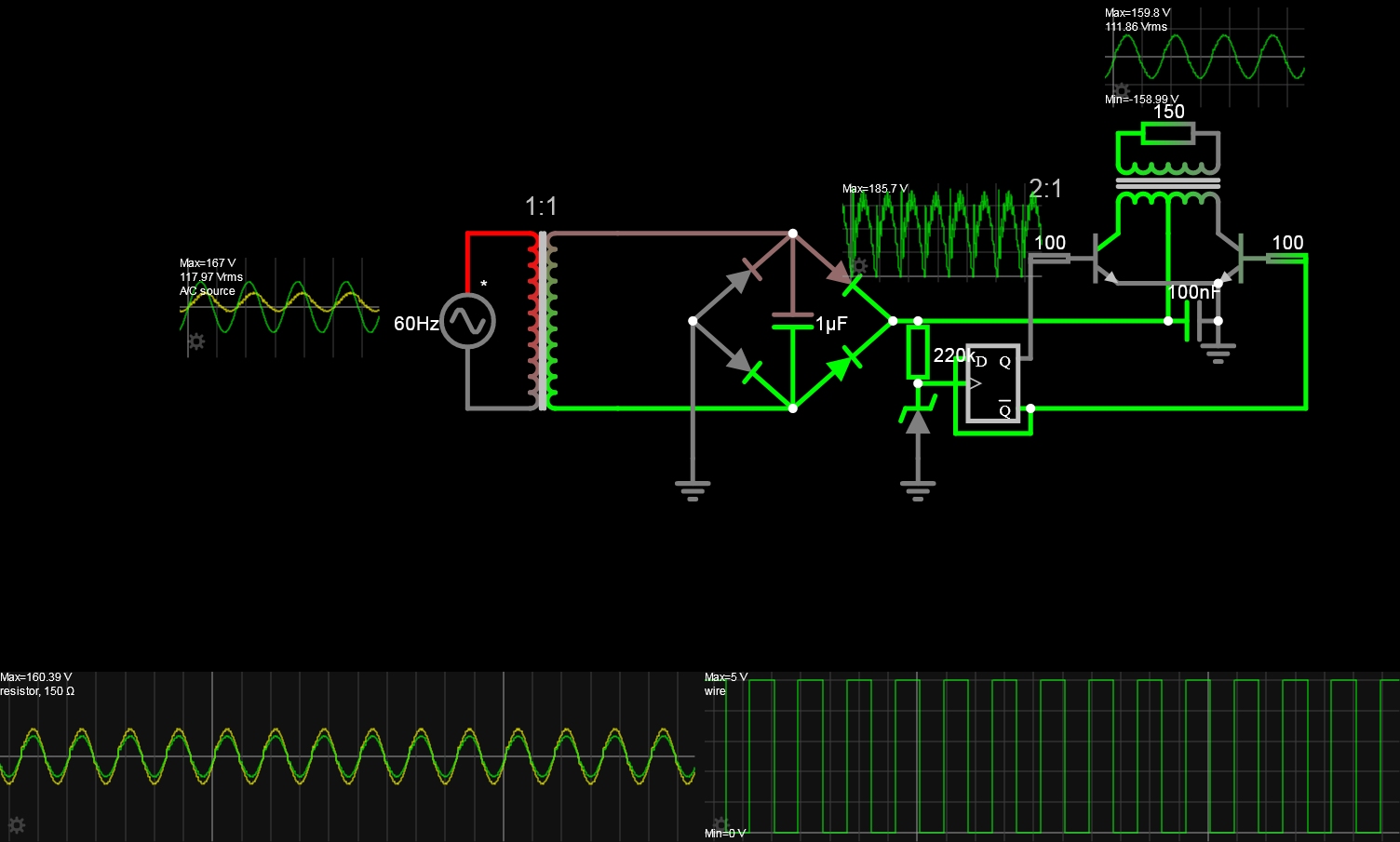
- This is about as simple an analog inverter that I can simulate, but warning, not for the beginner with resonance issues.
- The bridge diodes are 2f multipliers reduced to logic level with divide by 2 FF, then complementary inversion switches with a center tapped transformer with the tap having the isolated rectified power ***without filtering to low ripple DC.***
- 
- This is purely an academic Q&A and has no practical use with some issues not mentioned.
#2: Post edited
by
TonyStewart
·
2022-08-13T16:24:30Z (almost 3 years ago)
- This is about as simple an analog inverter that I can simulate, but warning, not for the beginner with resonance issues.
The bridge diodes are 2f multipliers reduced to logic level with divide by 2 FF, then complementary inversion switches with a center tapped transformer with the tap having the rectified power ***without filtering to low ripple DC.***- 
- This is about as simple an analog inverter that I can simulate, but warning, not for the beginner with resonance issues.
- The bridge diodes are 2f multipliers reduced to logic level with divide by 2 FF, then complementary inversion switches with a center tapped transformer with the tap having the isolated rectified power ***without filtering to low ripple DC.***
- 
#1: Initial revision
by
TonyStewart
·
2022-08-13T16:23:06Z (almost 3 years ago)
This is about as simple an analog inverter that I can simulate, but warning, not for the beginner with resonance issues. The bridge diodes are 2f multipliers reduced to logic level with divide by 2 FF, then complementary inversion switches with a center tapped transformer with the tap having the rectified power ***without filtering to low ripple DC.*** 