Post History
DC offsets in hundreds of mV from different grounds may be coming from either the floating ground or the PE earth. The latter may be from rectified AC line filter noise shunted to PE. The former m...
#3: Post edited
by
 TonyStewart
·
2022-09-25T12:55:18Z (over 2 years ago)
TonyStewart
·
2022-09-25T12:55:18Z (over 2 years ago)
Sensing high impedance signals with a different ground unbalances the signal and also creates a differential error.- In medical ECG, EEG high impedance signals achieve high SNR using common mode feedback to the shield also called "Guarding" when using a loop around traces or via's to reduce crosstalk. Another method is to use the common mode sense signal to create a virtual ground (=0V by definition) on the body and is standardized as the RLD or "right leg drive" signal.
- Also 120 dB CMRR INA INstrument Amplifiers IC's are mandatory and only degraded by the cables and probes due to differences in capacitance to ground imbalance. A common design also uses EMI filter capacitor values for AM and grid rejection when used with noise filters. If these were 10% tolerance caps to the CM node, they would degrade the CMRR so the value must be reduced to lower sensitivity and preferably using 1% C0G caps.
- Perhaps CM grid noise including AM radio is being rectified by the ESD protection diodes to create this offset. These might not be included in your simulation and may be imperfectly matched from process tolerances.
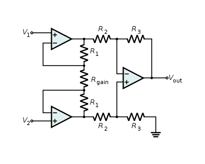
- **You should never use a single Op Amp buffer as you did to measure high impedance. rather 3 Op Amps in an [INA configuration](https://www.wikiwand.com/en/Instrumentation_amplifier) or a real INA IC. The sensor wires must be shielded twisted-pair (STP cable) for best results.**
- 
- DC offsets in hundreds of mV from different grounds may be coming from either the floating ground or the PE earth. The latter may be from rectified AC line filter noise shunted to PE. The former might be caused by front-end ESD protection diode rectification with DC bias and a CM signal large enough to cause DC leakage from any AC stray field (V/m) coupled by air capacitance which then can be rectified somewhat.
- Other info
- -
- Sensing high impedance signals with a different ground unbalances the signal and also creates a differential error. **Remember ground by definition is 0V only at that location** but loosely extended if you follow guidelines to prevent measurement or detection errors. This rule applies to all grounds incl. a floating battery and PE ground.
- In medical ECG, EEG high impedance signals achieve high SNR using common mode feedback to the shield also called "Guarding" when using a loop around traces or via's to reduce crosstalk. Another method is to use the common mode sense signal to create a virtual ground (=0V by definition) on the body and is standardized as the RLD or "right leg drive" signal.
- Also 120 dB CMRR INA INstrument Amplifiers IC's are mandatory and only degraded by the cables and probes due to differences in capacitance to ground imbalance. A common design also uses EMI filter capacitor values for AM and grid rejection when used with noise filters. If these were 10% tolerance caps to the CM node, they would degrade the CMRR so the value must be reduced to lower sensitivity and preferably using 1% C0G caps.
- Perhaps CM grid noise including AM radio is being rectified by the ESD protection diodes to create this offset. These might not be included in your simulation and may be imperfectly matched from process tolerances.
- **You should never use a single Op Amp buffer as you did to measure high impedance. rather 3 Op Amps in an [INA configuration](https://www.wikiwand.com/en/Instrumentation_amplifier) or a real INA IC. The sensor wires must be shielded twisted-pair (STP cable) for best results.**
- 
#2: Post edited
by
TonyStewart
·
2022-09-25T12:46:19Z (over 2 years ago)
- Sensing high impedance signals with a different ground unbalances the signal and also creates a differential error.
- In medical ECG, EEG high impedance signals achieve high SNR using common mode feedback to the shield also called "Guarding" when using a loop around traces or via's to reduce crosstalk. Another method is to use the common mode sense signal to create a virtual ground (=0V by definition) on the body and is standardized as the RLD or "right leg drive" signal.
- Also 120 dB CMRR INA INstrument Amplifiers IC's are mandatory and only degraded by the cables and probes due to differences in capacitance to ground imbalance. A common design also uses EMI filter capacitor values for AM and grid rejection when used with noise filters. If these were 10% tolerance caps to the CM node, they would degrade the CMRR so the value must be reduced to lower sensitivity and preferably using 1% C0G caps.
- Perhaps CM grid noise including AM radio is being rectified by the ESD protection diodes to create this offset. These might not be included in your simulation and may be imperfectly matched from process tolerances.
**You should never use a single Op Amp buffer as you did to measure high impedance. rather 3 Op Amps in an INA configuration or a real INA IC. The sensor wires must be shielded twisted-pair (STP cable) for best results.**
- Sensing high impedance signals with a different ground unbalances the signal and also creates a differential error.
- In medical ECG, EEG high impedance signals achieve high SNR using common mode feedback to the shield also called "Guarding" when using a loop around traces or via's to reduce crosstalk. Another method is to use the common mode sense signal to create a virtual ground (=0V by definition) on the body and is standardized as the RLD or "right leg drive" signal.
- Also 120 dB CMRR INA INstrument Amplifiers IC's are mandatory and only degraded by the cables and probes due to differences in capacitance to ground imbalance. A common design also uses EMI filter capacitor values for AM and grid rejection when used with noise filters. If these were 10% tolerance caps to the CM node, they would degrade the CMRR so the value must be reduced to lower sensitivity and preferably using 1% C0G caps.
- Perhaps CM grid noise including AM radio is being rectified by the ESD protection diodes to create this offset. These might not be included in your simulation and may be imperfectly matched from process tolerances.
- **You should never use a single Op Amp buffer as you did to measure high impedance. rather 3 Op Amps in an [INA configuration](https://www.wikiwand.com/en/Instrumentation_amplifier) or a real INA IC. The sensor wires must be shielded twisted-pair (STP cable) for best results.**
- 
#1: Initial revision
by
TonyStewart
·
2022-09-25T12:37:43Z (over 2 years ago)
Sensing high impedance signals with a different ground unbalances the signal and also creates a differential error.

In medical ECG, EEG high impedance signals achieve high SNR using common mode feedback to the shield also called "Guarding" when using a loop around traces or via's to reduce crosstalk. Another method is to use the common mode sense signal to create a virtual ground (=0V by definition) on the body and is standardized as the RLD or "right leg drive" signal.

Also 120 dB CMRR INA INstrument Amplifiers IC's are mandatory and only degraded by the cables and probes due to differences in capacitance to ground imbalance. A common design also uses EMI filter capacitor values for AM and grid rejection when used with noise filters. If these were 10% tolerance caps to the CM node, they would degrade the CMRR so the value must be reduced to lower sensitivity and preferably using 1% C0G caps.


Perhaps CM grid noise including AM radio is being rectified by the ESD protection diodes to create this offset. These might not be included in your simulation and may be imperfectly matched from process tolerances.

**You should never use a single Op Amp buffer as you did to measure high impedance. rather 3 Op Amps in an INA configuration or a real INA IC.  The sensor wires must be shielded twisted-pair (STP cable) for best results.**