Post History
A taper pad is a resistive attenuator that maintains impedances on both ports and provides a specific amount of gain-loss ($A_{12}$): - I have derived formulas for each resistor (that I know to ...
#7: Post edited
by
 Lorenzo Donati
·
2023-08-13T19:09:50Z (almost 2 years ago)
Lorenzo Donati
·
2023-08-13T19:09:50Z (almost 2 years ago)
Retagged.
#6: Post edited
by
 Andy aka
·
2022-10-09T16:40:03Z (over 2 years ago)
Andy aka
·
2022-10-09T16:40:03Z (over 2 years ago)
- A taper pad is a resistive attenuator that maintains impedances on both ports and provides a specific amount of gain-loss (\$A_{12}\$): -
- 
- I have derived formulas for each resistor (that I know to be correct) and have checked with micro-cap using DC analysis: -
- 
- "So what" you might think. Well the problem is really that it took me ages to derive the formulas and, I am convinced that there must be a simpler approach than the method I took so, what I'm looking for is a shrewd and insightful way of finding (say) the value of R1 given: -
- The required gain-loss i.e. \$\frac{V_2}{V_1}\$- - The input impedance, \$R_{IN}\$
- - The output load impedance, \$R_{L}\$
- I don't want answers that say if you "do this" you can "find that" then it's easy to drill-down to what you want. I want to see the actual math. I've done it (and my algebra is correct) but, it was very long-winded and I'm sure I missed a trick along the way.
- I will also add one more important thing that I've come to realize: none of the existing calculators out there (apart from mine) get the formulas correct. They show correct formulas for equal input and output impedance but, they screw up when the input and output impedances are different.
- A taper pad is a resistive attenuator that maintains impedances on both ports and provides a specific amount of gain-loss (\$A_{12}\$): -
- 
- I have derived formulas for each resistor (that I know to be correct) and have checked with micro-cap using DC analysis: -
- 
- "So what" you might think. Well the problem is really that it took me ages to derive the formulas and, I am convinced that there must be a simpler approach than the method I took so, what I'm looking for is a shrewd and insightful way of finding (say) the value of R1 given: -
- - The required gain-loss i.e. \$\frac{V_2}{V_1}\$ or \$\frac{V_{OUT}}{V_{IN}}\$
- - The input impedance, \$R_{IN}\$
- - The output load impedance, \$R_{L}\$
- I don't want answers that say if you "do this" you can "find that" then it's easy to drill-down to what you want. I want to see the actual math. I've done it (and my algebra is correct) but, it was very long-winded and I'm sure I missed a trick along the way.
- I will also add one more important thing that I've come to realize: none of the existing calculators out there (apart from mine) get the formulas correct. They show correct formulas for equal input and output impedance but, they screw up when the input and output impedances are different.
#5: Post edited
by
Andy aka
·
2022-10-09T16:38:41Z (over 2 years ago)
- A taper pad is a resistive attenuator that maintains impedances on both ports and provides a specific amount of gain-loss (\$A_{12}\$): -
- 
- I have derived formulas for each resistor (that I know to be correct) and have checked with micro-cap using DC analysis: -
- 
"So what" you might think. Well the problem is really that it took me absolutely ages to derive the formulas and, I am convinced that there must be a simpler approach than the method I took so, what I'm looking for is a shrewd and insightful way of finding (say) the value of R1 given: -- - The required gain-loss i.e. \$\frac{V_2}{V_1}\$
- - The input impedance, \$R_{IN}\$
- - The output load impedance, \$R_{L}\$
- I don't want answers that say if you "do this" you can "find that" then it's easy to drill-down to what you want. I want to see the actual math. I've done it (and my algebra is correct) but, it was very long-winded and I'm sure I missed a trick along the way.
- I will also add one more important thing that I've come to realize: none of the existing calculators out there (apart from mine) get the formulas correct. They show correct formulas for equal input and output impedance but, they screw up when the input and output impedances are different.
- A taper pad is a resistive attenuator that maintains impedances on both ports and provides a specific amount of gain-loss (\$A_{12}\$): -
- 
- I have derived formulas for each resistor (that I know to be correct) and have checked with micro-cap using DC analysis: -
- 
- "So what" you might think. Well the problem is really that it took me ages to derive the formulas and, I am convinced that there must be a simpler approach than the method I took so, what I'm looking for is a shrewd and insightful way of finding (say) the value of R1 given: -
- - The required gain-loss i.e. \$\frac{V_2}{V_1}\$
- - The input impedance, \$R_{IN}\$
- - The output load impedance, \$R_{L}\$
- I don't want answers that say if you "do this" you can "find that" then it's easy to drill-down to what you want. I want to see the actual math. I've done it (and my algebra is correct) but, it was very long-winded and I'm sure I missed a trick along the way.
- I will also add one more important thing that I've come to realize: none of the existing calculators out there (apart from mine) get the formulas correct. They show correct formulas for equal input and output impedance but, they screw up when the input and output impedances are different.
#4: Post edited
by
Andy aka
·
2022-10-09T16:37:44Z (over 2 years ago)
- A taper pad is a resistive attenuator that maintains impedances on both ports and provides a specific amount of gain-loss (\$A_{12}\$): -
- 
- I have derived formulas for each resistor (that I know to be correct) and have checked with micro-cap using DC analysis: -
- 
- "So what" you might think. Well the problem is really that it took me absolutely ages to derive the formulas and, I am convinced that there must be a simpler approach than the method I took so, what I'm looking for is a shrewd and insightful way of finding (say) the value of R1 given: -
- - The required gain-loss i.e. \$\frac{V_2}{V_1}\$
- - The input impedance, \$R_{IN}\$
- - The output load impedance, \$R_{L}\$
I don't want answers that say if you "do this" you can "find that" then it's easy to drill-down to what you want. I want to see the actual math. I've done it (and my algebra is correct) but, it was very long-winded and I'm sure I missed a trick along the way.
- A taper pad is a resistive attenuator that maintains impedances on both ports and provides a specific amount of gain-loss (\$A_{12}\$): -
- 
- I have derived formulas for each resistor (that I know to be correct) and have checked with micro-cap using DC analysis: -
- 
- "So what" you might think. Well the problem is really that it took me absolutely ages to derive the formulas and, I am convinced that there must be a simpler approach than the method I took so, what I'm looking for is a shrewd and insightful way of finding (say) the value of R1 given: -
- - The required gain-loss i.e. \$\frac{V_2}{V_1}\$
- - The input impedance, \$R_{IN}\$
- - The output load impedance, \$R_{L}\$
- I don't want answers that say if you "do this" you can "find that" then it's easy to drill-down to what you want. I want to see the actual math. I've done it (and my algebra is correct) but, it was very long-winded and I'm sure I missed a trick along the way.
- I will also add one more important thing that I've come to realize: none of the existing calculators out there (apart from mine) get the formulas correct. They show correct formulas for equal input and output impedance but, they screw up when the input and output impedances are different.
#3: Post edited
by
Andy aka
·
2022-10-09T16:34:07Z (over 2 years ago)
- A taper pad is a resistive attenuator that maintains impedances on both ports and provides a specific amount of gain-loss (\$A_{12}\$): -
- 
- I have derived formulas for each resistor (that I know to be correct) and have checked with micro-cap using DC analysis: -
- 
"So what" you might think. Well the problem is really that it took me absolutely ages to derive the formulas and I am convinced that there must be a simpler approach than the method I took so, what I'm looking for is a shrewd and insightful way of finding (say) the value of R1 given: -- - The required gain-loss i.e. \$\frac{V_2}{V_1}\$
- - The input impedance, \$R_{IN}\$
- - The output load impedance, \$R_{L}\$
I don't want answers that say if you "do this" you can "find that" then it's easy to drill-down to what you want. I want to see the actual math. I've done it (and the answers are correct) but, it was very long-winded and I'm sure I missed a trick along the way.
- A taper pad is a resistive attenuator that maintains impedances on both ports and provides a specific amount of gain-loss (\$A_{12}\$): -
- 
- I have derived formulas for each resistor (that I know to be correct) and have checked with micro-cap using DC analysis: -
- 
- "So what" you might think. Well the problem is really that it took me absolutely ages to derive the formulas and, I am convinced that there must be a simpler approach than the method I took so, what I'm looking for is a shrewd and insightful way of finding (say) the value of R1 given: -
- - The required gain-loss i.e. \$\frac{V_2}{V_1}\$
- - The input impedance, \$R_{IN}\$
- - The output load impedance, \$R_{L}\$
- I don't want answers that say if you "do this" you can "find that" then it's easy to drill-down to what you want. I want to see the actual math. I've done it (and my algebra is correct) but, it was very long-winded and I'm sure I missed a trick along the way.
#2: Post edited
by
Andy aka
·
2022-10-09T16:14:00Z (over 2 years ago)
Deriving resistor values in a taper pad attenuator
- Deriving resistor values for a taper pad attenuator
#1: Initial revision
by
Andy aka
·
2022-10-09T16:13:38Z (over 2 years ago)
Deriving resistor values in a taper pad attenuator
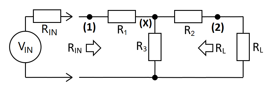
A taper pad is a resistive attenuator that maintains impedances on both ports and provides a specific amount of gain-loss (\$A_{12}\$): -

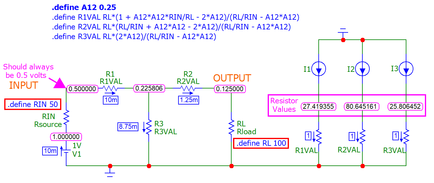
I have derived formulas for each resistor (that I know to be correct) and have checked with micro-cap using DC analysis: -

"So what" you might think. Well the problem is really that it took me absolutely ages to derive the formulas and I am convinced that there must be a simpler approach than the method I took so, what I'm looking for is a shrewd and insightful way of finding (say) the value of R1 given: -
- The required gain-loss i.e. \$\frac{V_2}{V_1}\$
- The input impedance, \$R_{IN}\$
- The output load impedance, \$R_{L}\$
I don't want answers that say if you "do this" you can "find that" then it's easy to drill-down to what you want. I want to see the actual math. I've done it (and the answers are correct) but, it was very long-winded and I'm sure I missed a trick along the way.