Post History
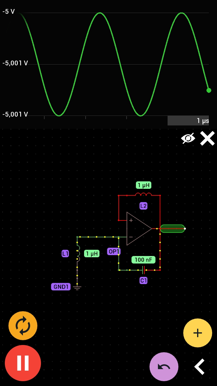
1- What we call this opamp configuration? 2- What's the advantage and the disadvantage of this circuit? 3- And what's the purpose of the L2 in the feedback? I have changed gradually the value of...
#8: Post edited
- 1- What we call this opamp configuration?
- 2- What's the advantage and the disadvantage of this circuit?
- 3- And what's the purpose of the L2 in the feedback?
- I have changed gradually the value of L2 from 1 pH to hundreds of H but nothing noticeable, then I replaced it with a resistor and did the same process the result was the same, in the end I replaced them with a wire the result was also the same.
- 
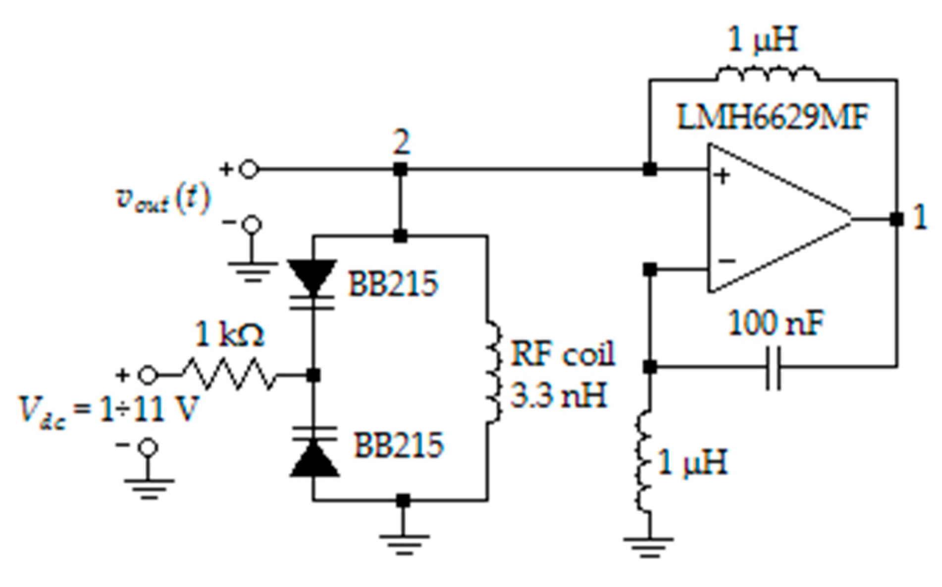
- **Edit:** this circuit was designed in National Aviation University of Kyiv, Ukraine.
- The circuit is suposed to exhibits a maximum in-band total harmonic distortion (THD) of 1.7%. And a maximum in-band phase noise of −139.3 dBc/Hz at 100 kHz offset frequency and has an outstanding value of a standard figure of merit (FoM) of −198.6 dBc/Hz.
- 
- **Edit2:**
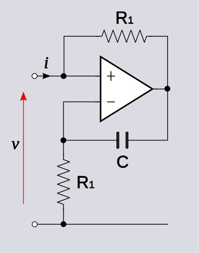
- For question 3 the inductor L1 provides positive shunt–shunt feedback.
- **Edit3:**
- For question 1 the opamp configuration is a Negative inductance circuit, a type of negative impedance converter.
- [Negative impedance converter](https://en.m.wikipedia.org/wiki/Negative_impedance_converter)
- 1- What we call this opamp configuration?
- 2- What's the advantage and the disadvantage of this circuit?
- 3- And what's the purpose of the L2 in the feedback?
- I have changed gradually the value of L2 from 1 pH to hundreds of H but nothing noticeable, then I replaced it with a resistor and did the same process the result was the same, in the end I replaced them with a wire the result was also the same.
- 
- **Edit:** this circuit was designed in National Aviation University of Kyiv, Ukraine.
- The circuit is suposed to exhibits a maximum in-band total harmonic distortion (THD) of 1.7%. And a maximum in-band phase noise of −139.3 dBc/Hz at 100 kHz offset frequency and has an outstanding value of a standard figure of merit (FoM) of −198.6 dBc/Hz.
- 
- **Edit2:**
- For question 3 the inductor L1 provides positive shunt–shunt feedback.
- **Edit3:**
- For question 1 the opamp configuration is a Negative inductance circuit, a type of negative impedance converter.
- [Negative impedance converter](https://en.m.wikipedia.org/wiki/Negative_impedance_converter)
- 
- This circuit can be configurated in different ways the negative of any impedance can be produced, including negative capacitance and negative inductance.
#7: Post edited
- 1- What we call this opamp configuration?
- 2- What's the advantage and the disadvantage of this circuit?
- 3- And what's the purpose of the L2 in the feedback?
- I have changed gradually the value of L2 from 1 pH to hundreds of H but nothing noticeable, then I replaced it with a resistor and did the same process the result was the same, in the end I replaced them with a wire the result was also the same.
- **Edit:** this circuit was designed in National Aviation University of Kyiv, Ukraine.
The circuit is suposed to exhibits a maximum in-band total harmonic distortion (THD) of 1.7%. And has a maximum in-band phase noise of −139.3 dBc/Hz at 100 kHz offset frequency and has an outstanding value of a standard figure of merit (FoM) of −198.6 dBc/Hz.- 
- **Edit2:**
- For question 3 the inductor L1 provides positive shunt–shunt feedback.
- **Edit3:**
- For question 1 the opamp configuration is a Negative inductance circuit, a type of negative impedance converter.
- [Negative impedance converter](https://en.m.wikipedia.org/wiki/Negative_impedance_converter)
- 
- 1- What we call this opamp configuration?
- 2- What's the advantage and the disadvantage of this circuit?
- 3- And what's the purpose of the L2 in the feedback?
- I have changed gradually the value of L2 from 1 pH to hundreds of H but nothing noticeable, then I replaced it with a resistor and did the same process the result was the same, in the end I replaced them with a wire the result was also the same.
- 
- **Edit:** this circuit was designed in National Aviation University of Kyiv, Ukraine.
- The circuit is suposed to exhibits a maximum in-band total harmonic distortion (THD) of 1.7%. And a maximum in-band phase noise of −139.3 dBc/Hz at 100 kHz offset frequency and has an outstanding value of a standard figure of merit (FoM) of −198.6 dBc/Hz.
- 
- **Edit2:**
- For question 3 the inductor L1 provides positive shunt–shunt feedback.
- **Edit3:**
- For question 1 the opamp configuration is a Negative inductance circuit, a type of negative impedance converter.
- [Negative impedance converter](https://en.m.wikipedia.org/wiki/Negative_impedance_converter)
- 
#6: Post edited
What we call this opamp configuration?
- What we call this opamp configuration? [SOLVED]
- 1- What we call this opamp configuration?
- 2- What's the advantage and the disadvantage of this circuit?
- 3- And what's the purpose of the L2 in the feedback?
- I have changed gradually the value of L2 from 1 pH to hundreds of H but nothing noticeable, then I replaced it with a resistor and did the same process the result was the same, in the end I replaced them with a wire the result was also the same.
- 
- **Edit:** this circuit was designed in National Aviation University of Kyiv, Ukraine.
- The circuit is suposed to exhibits a maximum in-band total harmonic distortion (THD) of 1.7%. And has a maximum in-band phase noise of −139.3 dBc/Hz at 100 kHz offset frequency and has an outstanding value of a standard figure of merit (FoM) of −198.6 dBc/Hz.
- 
- **Edit2:**
For question 3 the inductor L1 provides positive shunt–shunt feedback.
- 1- What we call this opamp configuration?
- 2- What's the advantage and the disadvantage of this circuit?
- 3- And what's the purpose of the L2 in the feedback?
- I have changed gradually the value of L2 from 1 pH to hundreds of H but nothing noticeable, then I replaced it with a resistor and did the same process the result was the same, in the end I replaced them with a wire the result was also the same.
- 
- **Edit:** this circuit was designed in National Aviation University of Kyiv, Ukraine.
- The circuit is suposed to exhibits a maximum in-band total harmonic distortion (THD) of 1.7%. And has a maximum in-band phase noise of −139.3 dBc/Hz at 100 kHz offset frequency and has an outstanding value of a standard figure of merit (FoM) of −198.6 dBc/Hz.
- 
- **Edit2:**
- For question 3 the inductor L1 provides positive shunt–shunt feedback.
- **Edit3:**
- For question 1 the opamp configuration is a Negative inductance circuit, a type of negative impedance converter.
- [Negative impedance converter](https://en.m.wikipedia.org/wiki/Negative_impedance_converter)
- 
#5: Post edited
What we call this opamp configuration?What's the advantage and the disadvantage of this circuit?And what's the purpose of the L2 in the feedback?- I have changed gradually the value of L2 from 1 pH to hundreds of H but nothing noticeable, then I replaced it with a resistor and did the same process the result was the same, in the end I replaced them with a wire the result was also the same.
- 
- **Edit:** this circuit was designed in National Aviation University of Kyiv, Ukraine.
- The circuit is suposed to exhibits a maximum in-band total harmonic distortion (THD) of 1.7%. And has a maximum in-band phase noise of −139.3 dBc/Hz at 100 kHz offset frequency and has an outstanding value of a standard figure of merit (FoM) of −198.6 dBc/Hz.

- 1- What we call this opamp configuration?
- 2- What's the advantage and the disadvantage of this circuit?
- 3- And what's the purpose of the L2 in the feedback?
- I have changed gradually the value of L2 from 1 pH to hundreds of H but nothing noticeable, then I replaced it with a resistor and did the same process the result was the same, in the end I replaced them with a wire the result was also the same.
- 
- **Edit:** this circuit was designed in National Aviation University of Kyiv, Ukraine.
- The circuit is suposed to exhibits a maximum in-band total harmonic distortion (THD) of 1.7%. And has a maximum in-band phase noise of −139.3 dBc/Hz at 100 kHz offset frequency and has an outstanding value of a standard figure of merit (FoM) of −198.6 dBc/Hz.
- 
- **Edit2:**
- For question 3 the inductor L1 provides positive shunt–shunt feedback.
#4: Post edited
- What we call this opamp configuration?
- What's the advantage and the disadvantage of this circuit?
- And what's the purpose of the L2 in the feedback?
- I have changed gradually the value of L2 from 1 pH to hundreds of H but nothing noticeable, then I replaced it with a resistor and did the same process the result was the same, in the end I replaced them with a wire the result was also the same.
- 
- **Edit:** this circuit was designed in National Aviation University of Kyiv, Ukraine.
This circuit is suposed to exhibits a maximum in-band total harmonic distortion (THD) of 1.7%. And has a maximum in-band phase noise of −139.3 dBc/Hz at 100 kHz offset frequency and has an outstanding value of a standard figure of merit (FoM) of −198.6 dBc/Hz.- 
- What we call this opamp configuration?
- What's the advantage and the disadvantage of this circuit?
- And what's the purpose of the L2 in the feedback?
- I have changed gradually the value of L2 from 1 pH to hundreds of H but nothing noticeable, then I replaced it with a resistor and did the same process the result was the same, in the end I replaced them with a wire the result was also the same.
- 
- **Edit:** this circuit was designed in National Aviation University of Kyiv, Ukraine.
- The circuit is suposed to exhibits a maximum in-band total harmonic distortion (THD) of 1.7%. And has a maximum in-band phase noise of −139.3 dBc/Hz at 100 kHz offset frequency and has an outstanding value of a standard figure of merit (FoM) of −198.6 dBc/Hz.
- 
#3: Post edited
- What we call this opamp configuration?
- What's the advantage and the disadvantage of this circuit?
- And what's the purpose of the L2 in the feedback?
- I have changed gradually the value of L2 from 1 pH to hundreds of H but nothing noticeable, then I replaced it with a resistor and did the same process the result was the same, in the end I replaced them with a wire the result was also the same.
- 
**Edit:**
- What we call this opamp configuration?
- What's the advantage and the disadvantage of this circuit?
- And what's the purpose of the L2 in the feedback?
- I have changed gradually the value of L2 from 1 pH to hundreds of H but nothing noticeable, then I replaced it with a resistor and did the same process the result was the same, in the end I replaced them with a wire the result was also the same.
- 
- **Edit:** this circuit was designed in National Aviation University of Kyiv, Ukraine.
- This circuit is suposed to exhibits a maximum in-band total harmonic distortion (THD) of 1.7%. And has a maximum in-band phase noise of −139.3 dBc/Hz at 100 kHz offset frequency and has an outstanding value of a standard figure of merit (FoM) of −198.6 dBc/Hz.
- 
#2: Post edited
- What we call this opamp configuration?
- What's the advantage and the disadvantage of this circuit?
- And what's the purpose of the L2 in the feedback?
- I have changed gradually the value of L2 from 1 pH to hundreds of H but nothing noticeable, then I replaced it with a resistor and did the same process the result was the same, in the end I replaced them with a wire the result was also the same.
- 
- **Edit:**
- 
#1: Initial revision
What we call this opamp configuration?
What we call this opamp configuration? What's the advantage and the disadvantage of this circuit? And what's the purpose of the L2 in the feedback? I have changed gradually the value of L2 from 1 pH to hundreds of H but nothing noticeable, then I replaced it with a resistor and did the same process the result was the same, in the end I replaced them with a wire the result was also the same. 